EP0098097B1 - Schaufelregulierte Flüssigkeitskupplung - Google Patents
Schaufelregulierte Flüssigkeitskupplung Download PDFInfo
- Publication number
- EP0098097B1 EP0098097B1 EP83303609A EP83303609A EP0098097B1 EP 0098097 B1 EP0098097 B1 EP 0098097B1 EP 83303609 A EP83303609 A EP 83303609A EP 83303609 A EP83303609 A EP 83303609A EP 0098097 B1 EP0098097 B1 EP 0098097B1
- Authority
- EP
- European Patent Office
- Prior art keywords
- runner
- holes
- outer profile
- impeller
- scoop
- Prior art date
- Legal status (The legal status is an assumption and is not a legal conclusion. Google has not performed a legal analysis and makes no representation as to the accuracy of the status listed.)
- Expired
Links
Images



Classifications
-
- F—MECHANICAL ENGINEERING; LIGHTING; HEATING; WEAPONS; BLASTING
- F16—ENGINEERING ELEMENTS AND UNITS; GENERAL MEASURES FOR PRODUCING AND MAINTAINING EFFECTIVE FUNCTIONING OF MACHINES OR INSTALLATIONS; THERMAL INSULATION IN GENERAL
- F16D—COUPLINGS FOR TRANSMITTING ROTATION; CLUTCHES; BRAKES
- F16D33/00—Rotary fluid couplings or clutches of the hydrokinetic type
- F16D33/06—Rotary fluid couplings or clutches of the hydrokinetic type controlled by changing the amount of liquid in the working circuit
- F16D33/08—Rotary fluid couplings or clutches of the hydrokinetic type controlled by changing the amount of liquid in the working circuit by devices incorporated in the fluid coupling, with or without remote control
- F16D33/14—Rotary fluid couplings or clutches of the hydrokinetic type controlled by changing the amount of liquid in the working circuit by devices incorporated in the fluid coupling, with or without remote control consisting of shiftable or adjustable scoops
Definitions
- the present invention relates to scoop-controlled fluid couplings.
- a scoop-controlled fluid coupling comprises (as known for example from GB-A-908853) coaxially mounted impeller and runner elements, each in the form of a dished and vaned shell together defining a working circuit for working liquid, a reservoir casing rotatable with the impeller for holding working liquid radially outside the working circuit, a movable scoop having a scooping tip adjustable to different radial positions in the reservoir casing, for collecting liquid from the rotating ring of liquid held therein and for returning it, optionally via a cooler, to the working circuit, from which the working liquid can return to the reservoir through one or more restricted outlets.
- Such scoop-controlled couplings are often incorporated in drives for high inertia loads such as long conveyor belts for coal and other minerals.
- Such conveyor belts may be several kilometres in length but of relatively light belt construction. It is therefore essential that no excessive driving loads should be exerted on the belt, especially during start-up, which may take several minutes.
- a long conveyor belt can have two or more driving heads distributed along its length, and each drive may have two driving motors, each driving into a separate fluid coupling, there may be a requirement, under emergency conditions, for example failure of one or more motors or their supplies for a reduced number of motors to be able to accelerate the load from rest to working speed without over- stressing the belt or heating the fluid coupling beyond permissible limits.
- the load to be applied is small compared with the full motor load.
- the low starting torque is achieved by appropriately lengthening the starting operation.
- the scoop-operating lever of the coupling is moved gradually over its full travel, in say three or more minutes during which time the coupling is operating with a decreasing but obviously large degree of slip with corresponding heat generation.
- a scoop-controlled coupling according to the present invention is characterised in that the outer profile diameter of the runner is from 5 to 15%, preferably 10 to 15%, less than the outer profile diameter of the impeller, and in that one of the vaned elements, preferably the runner, has two sets of holes drilled through its shell the centres of one set of holes being spaced from the coupling axis by from 53 to 63%, preferably 58%, of the outer profile radius, and the centres of the second set of holes being spaced from the coupling axis by 65 to 75%, preferably 70%, of the outer profile radius.
- the runner is highly advantageous for the runner to be of the kind disclosed in British Patent Specification No. 669331, that is to say in which the shapes of some of the intervane pockets of the runner element, as disclosed by section planes containing the axis of rotation of the coupling, differ from the shapes of other pockets of the same runner element, the runner element being preferably provided with core guide means wherein the shapes of some the intervane passages between the core guide means and the dished shell of the runner element, as disclosed by the said section planes, differ from the shapes of the other inter- vane passages.
- the scoop-controlled coupling shown in Figs. 1 and 2 follows conventional practice in so far as it comprises a stationary cast iron bracket 1 in which an output shaft 2 is partially supported by a self-aligning bearing 3.
- An input sleeve 4 is connected by a flexible driving plate 5 to an impeller assembly 6 which is supported on the output shaft 2 by bearings 7 and 8.
- the impeller assembly 6 comprises an outer reservoir casing 9 and an inner impeller casing 10 the which is secured a dished impeller 11 of conventional design.
- a runner 12 to be described in more detail below, defines, with the impeller 11, a working circuit W.
- the runner 12 is bolted to a flange 13 on the output shaft 2 with the inter position of an annular baffle 14.
- the bearing 7 supports the hub of the impeller 11 on the output shaft 2.
- a radially slidable scoop tube 15 has a scooping orifice 16 movable over a range of positions within the reservoir formed by the casing 9.
- a scoop control lever 17 is mounted on a shaft 18 which is supported in the bracket 1 and carries a swing arm 19 formed with a slot which receives a pin on the scoop tube 15.
- the scoop tube has an outlet (not shown) which connects with an external cooler from which working liquid is returned to an annular collecting ring 21 in the impeller hub from which the liquid returns to the working circuit W through shielded inlet ports 22.
- Working liquids leaves the working circuit W at a restricted rate through conventional leak-off nozzles 23 into the reservoir 9.
- the nozzles 23 may be replaced by known quick- emptying valves controlled by tubes 24, if required.
- the runner 12 In a conventional coupling, the runner 12 would have the same internal and external profile diameters as the impeller 11. The runner would have vanes similar to the impeller (but different in number and arrangement), but without any core guide means.
- the curves shown in Fig. 3 are obtained with a conventional coupling when installed in the test rig shown in Fig. 5 in which the inertia of a conveyor is represented by a flywheel assembly 41 and step-up gear box 42 while its running resistance is represented by a brake 47.
- a friction brake 43 enables the load system to be held stationary at the commencement of each test cycle and then be released at the appropriate time to simulate breakaway.
- the coupling 40 is mounted between a motor and gear box assembly 44 and 45, while the output torque is measured by a transducer 46, enabling the transmitted power to be determined.
- Fig. 3 it will be seen that in each test, the coupling starts with the working circuit empty at the right hand end of the figure, corresponding to 100% slip.
- the curves shown in Fig. 3A were obtained with the scoop positioned 45% of the distance from its "working circuit empty” position to the "working circuit full” position.
- Figs. 3B, C, D, E corresponds to the 55%, 60%, 64% and 69% travel positions.
- the curves should be substantially level or slope downwards to the left. In fact, it is found that as a result of the prolonged acceleration times and the corresponding temperature rise, the curves tend to rise towards the left instead of falling resulting in an unacceptable 'hardening' of the coupling i.e. increased transmitted torque with an increased driving force on the load.
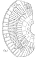
- the runner 12 in Figs. 1 and 2 is generally of the kind shown in Fig. 1 of British specification No. 669331.
- its vanes 51 carry short sections 52 of a core guide which vary in dimensions around the axis of the runner, increasing in size from the smallest 51 a to the largest 51f.
- the wall 53 of the runner has inner and outer sets of holes 54 and 55 drilled through it on pitch circle diameters which are respectively 58% and 70% of the outer profile diameter of the runner (in this case 36 inches or 914 mm).
- Each hole 54,55 is about 11 mm in diameter and thus about 0.012timesthe outer profile diameter of the runner.
- the runner may have 45 or 54 vanes.
- the holes 54 are drilled through alternate vane pockets and the holes 55 in the other vane pockets (not containing a hole 54).
- the outer profile diameter of the runner 12 is about 10% less than that of the impeller 11. This is conveniently achieved by selecting a runner designed for a smaller size of coupling where there is a standard range available.
- the pattern shown in Fig. 2 is repeated in each of the other two thirds of the runner.
- a segmental filler ring 56 is bolted to the inner casing of the impeller assembly, gaps in this ring communicating with the nozzles 23.
- the baffle 14 is of reduced external diameter, typically 1.3x the inner profile diameter of the working circuit.
- the diameter of the holes 54, 55 is in the range 1 to 1.6% of the outer profile diameter of the runner.
Landscapes
- Engineering & Computer Science (AREA)
- General Engineering & Computer Science (AREA)
- Mechanical Engineering (AREA)
- Structures Of Non-Positive Displacement Pumps (AREA)
- Quick-Acting Or Multi-Walled Pipe Joints (AREA)
Claims (6)
Applications Claiming Priority (2)
| Application Number | Priority Date | Filing Date | Title |
|---|---|---|---|
| GB8218002 | 1982-06-22 | ||
| GB8218002 | 1982-06-22 |
Publications (3)
| Publication Number | Publication Date |
|---|---|
| EP0098097A2 EP0098097A2 (de) | 1984-01-11 |
| EP0098097A3 EP0098097A3 (en) | 1985-01-16 |
| EP0098097B1 true EP0098097B1 (de) | 1987-12-23 |
Family
ID=10531203
Family Applications (1)
| Application Number | Title | Priority Date | Filing Date |
|---|---|---|---|
| EP83303609A Expired EP0098097B1 (de) | 1982-06-22 | 1983-06-22 | Schaufelregulierte Flüssigkeitskupplung |
Country Status (9)
| Country | Link |
|---|---|
| US (1) | US4671061A (de) |
| EP (1) | EP0098097B1 (de) |
| JP (1) | JPS599320A (de) |
| AU (1) | AU565891B2 (de) |
| BR (1) | BR8303451A (de) |
| CA (1) | CA1209440A (de) |
| DE (1) | DE3375041D1 (de) |
| GB (1) | GB2123533B (de) |
| ZA (1) | ZA834418B (de) |
Families Citing this family (16)
| Publication number | Priority date | Publication date | Assignee | Title |
|---|---|---|---|---|
| US5120196A (en) * | 1991-03-11 | 1992-06-09 | General Motors Corporation | Impeller for a torque converter |
| US5668663A (en) * | 1994-05-05 | 1997-09-16 | Donnelly Corporation | Electrochromic mirrors and devices |
| DE19614589A1 (de) * | 1996-04-12 | 1997-10-16 | Voith Turbo Kg | Hydrodynamische Kupplung |
| JPH10196686A (ja) * | 1996-12-27 | 1998-07-31 | Ebara Corp | 流体継手 |
| DE10046833A1 (de) * | 2000-08-30 | 2002-03-28 | Voith Turbo Kg | Hydrodynamische Baueinheit |
| BR0113598A (pt) | 2000-08-30 | 2003-07-15 | Voith Turbo Kg | Processo para o controle do consumo de potência de uma embreagem hidrodinâmica por meio do controle do grau de enchimento e de uma embreagem hidrodinâmica |
| US6769248B2 (en) * | 2002-06-13 | 2004-08-03 | Turbo Research, Inc. | Fluid coupling for mobile equipment |
| RU2410247C2 (ru) * | 2004-02-26 | 2011-01-27 | Вентек, Ллк | Вспомогательная нагревательная система транспортного средства |
| US6996978B2 (en) * | 2004-05-05 | 2006-02-14 | Goerend David J | Torque converter stator |
| DE102005004524B3 (de) * | 2005-01-31 | 2006-05-18 | Voith Turbo Gmbh & Co. Kg | Hydrodynamische Maschine, zum Beispiel hydrodynamische Kupplung oder hydrodynamische Bremse |
| DE102006033093A1 (de) * | 2006-07-14 | 2008-01-17 | Voith Turbo Gmbh & Co. Kg | Füllungsgesteuerte hydrodynamische Kupplung und Verfahren zum Betrieb derselben |
| US8480006B2 (en) | 2006-09-08 | 2013-07-09 | Ventech, Llc | Vehicle supplemental heating system |
| DE102007034562A1 (de) * | 2007-07-25 | 2009-01-29 | Zf Friedrichshafen Ag | Hydrodynamischer Retarder mit tangentialem Zu- und Abströmprinzip |
| DE112008001862A5 (de) * | 2007-08-31 | 2010-04-22 | Luk Lamellen Und Kupplungsbau Beteiligungs Kg | Drehmomentwandler und Verfahren zum Herstellen einer Schale einem Drehmomentwandlers |
| EP2313284B1 (de) | 2008-07-29 | 2019-10-16 | Ventech, LLC | Zusätzliches heizsystem mit intergriertem wärmetauscher |
| US9841211B2 (en) | 2015-08-24 | 2017-12-12 | Ventech, Llc | Hydrodynamic heater |
Citations (1)
| Publication number | Priority date | Publication date | Assignee | Title |
|---|---|---|---|---|
| GB908853A (en) * | 1959-09-08 | 1962-10-24 | Harold Sinclair | Improvements in hydraulic turbo couplings |
Family Cites Families (10)
| Publication number | Priority date | Publication date | Assignee | Title |
|---|---|---|---|---|
| DE179486C (de) * | ||||
| DE687919C (de) * | 1936-07-07 | 1940-02-08 | Klein | iebes nach dem Stroemungsprinzip |
| US2407496A (en) * | 1943-06-28 | 1946-09-10 | Bendix Aviat Corp | Fluid transmission |
| GB669331A (en) * | 1949-01-18 | 1952-04-02 | Harold Sinclair | Improvements in hydraulic couplings |
| DE906872C (de) * | 1949-01-18 | 1954-03-18 | Harold Sinclair | Fuellungsveraenderliche Stroemungskupplung mit radialen oder im wesentlichen radialen Schaufeln |
| DE1031641B (de) * | 1957-01-29 | 1958-06-04 | Rudi Mueller | Selbstansaugende Umlaufpumpe |
| US3037459A (en) * | 1958-09-17 | 1962-06-05 | American Radiator & Standard | Balanced pressure rotor vane |
| GB1346677A (en) * | 1971-09-14 | 1974-02-13 | Daimler Benz Ag | Hydrodynamic transmission |
| GB1484011A (en) * | 1973-08-09 | 1977-08-24 | Fluidrive Eng Co Ltd | Fluid couplings |
| DE2815245C3 (de) * | 1978-04-08 | 1981-07-02 | Klöckner-Humboldt-Deutz AG, 5000 Köln | Kühlgebläseantrieb |
-
1983
- 1983-06-15 CA CA000430401A patent/CA1209440A/en not_active Expired
- 1983-06-16 ZA ZA834418A patent/ZA834418B/xx unknown
- 1983-06-17 AU AU15890/83A patent/AU565891B2/en not_active Ceased
- 1983-06-21 JP JP58111779A patent/JPS599320A/ja active Pending
- 1983-06-22 GB GB08317005A patent/GB2123533B/en not_active Expired
- 1983-06-22 EP EP83303609A patent/EP0098097B1/de not_active Expired
- 1983-06-22 DE DE8383303609T patent/DE3375041D1/de not_active Expired
- 1983-06-22 BR BR8303451A patent/BR8303451A/pt unknown
-
1985
- 1985-04-26 US US06/726,955 patent/US4671061A/en not_active Expired - Fee Related
Patent Citations (1)
| Publication number | Priority date | Publication date | Assignee | Title |
|---|---|---|---|---|
| GB908853A (en) * | 1959-09-08 | 1962-10-24 | Harold Sinclair | Improvements in hydraulic turbo couplings |
Also Published As
| Publication number | Publication date |
|---|---|
| CA1209440A (en) | 1986-08-12 |
| JPS599320A (ja) | 1984-01-18 |
| GB2123533A (en) | 1984-02-01 |
| AU1589083A (en) | 1984-01-05 |
| EP0098097A3 (en) | 1985-01-16 |
| DE3375041D1 (en) | 1988-02-04 |
| GB2123533B (en) | 1986-06-25 |
| EP0098097A2 (de) | 1984-01-11 |
| GB8317005D0 (en) | 1983-07-27 |
| BR8303451A (pt) | 1984-02-07 |
| US4671061A (en) | 1987-06-09 |
| ZA834418B (en) | 1984-05-30 |
| AU565891B2 (en) | 1987-10-01 |
Similar Documents
| Publication | Publication Date | Title |
|---|---|---|
| EP0098097B1 (de) | Schaufelregulierte Flüssigkeitskupplung | |
| US4597481A (en) | Hydrodynamic control coupling | |
| US3020719A (en) | Variable slip fluid coupling | |
| US2714946A (en) | Hydraulic transmission | |
| US3919844A (en) | Fluid couplings | |
| US2318660A (en) | Automatic hydraulic transmission | |
| US5105793A (en) | Mechanical driving mechanism of a supercharger for an internal combustion engine | |
| US5749416A (en) | Downhole pump drive head assembly | |
| US2318187A (en) | Automatic control for fluid transmissions | |
| US1963720A (en) | Hydraulic coupling | |
| US2162803A (en) | Fluid clutch and turbo-torque converter | |
| US3178889A (en) | Fluid coupling | |
| US2415670A (en) | Aerodynamic brake | |
| US4094143A (en) | Variable torque hydraulic clutch | |
| CA2171899C (en) | Downhole pump drive head assembly | |
| US3981186A (en) | Device for blocking at a given torque a rotating machine driven by a hydraulic turbine | |
| EP0508528A1 (de) | Entleerende Flüssigkeitskupplung mit kontinuierlicher Steuerung der Flüssigkeitsmenge zur Speisung des Arbeitsraums, mit oder ohne interner Vorrichtung zum Direktverbinden der treibenden und getriebenen Welle | |
| US3165894A (en) | Torque limiting ports-fluid drives | |
| US2393859A (en) | Torque converter | |
| EP0204397A1 (de) | Strömungskupplung mit veränderlicher Geschwindigkeit | |
| US2287374A (en) | Hydraulic torque converter | |
| CN102606645B (zh) | 具有多级的前室的液压耦合器 | |
| US3156095A (en) | Hydraulic transmissions | |
| US2448855A (en) | Aerodynamic brake and hoist combination | |
| US3029902A (en) | Hydro-kinetic brakes and couplings |
Legal Events
| Date | Code | Title | Description |
|---|---|---|---|
| PUAI | Public reference made under article 153(3) epc to a published international application that has entered the european phase |
Free format text: ORIGINAL CODE: 0009012 |
|
| AK | Designated contracting states |
Designated state(s): DE FR IT |
|
| PUAL | Search report despatched |
Free format text: ORIGINAL CODE: 0009013 |
|
| AK | Designated contracting states |
Designated state(s): DE FR IT |
|
| 17P | Request for examination filed |
Effective date: 19850712 |
|
| 17Q | First examination report despatched |
Effective date: 19860505 |
|
| ITF | It: translation for a ep patent filed | ||
| GRAA | (expected) grant |
Free format text: ORIGINAL CODE: 0009210 |
|
| AK | Designated contracting states |
Kind code of ref document: B1 Designated state(s): DE FR IT |
|
| REF | Corresponds to: |
Ref document number: 3375041 Country of ref document: DE Date of ref document: 19880204 |
|
| ET | Fr: translation filed | ||
| PLBE | No opposition filed within time limit |
Free format text: ORIGINAL CODE: 0009261 |
|
| STAA | Information on the status of an ep patent application or granted ep patent |
Free format text: STATUS: NO OPPOSITION FILED WITHIN TIME LIMIT |
|
| 26N | No opposition filed | ||
| PG25 | Lapsed in a contracting state [announced via postgrant information from national office to epo] |
Ref country code: FR Free format text: LAPSE BECAUSE OF NON-PAYMENT OF DUE FEES Effective date: 19890228 |
|
| PG25 | Lapsed in a contracting state [announced via postgrant information from national office to epo] |
Ref country code: DE Effective date: 19890301 |
|
| REG | Reference to a national code |
Ref country code: FR Ref legal event code: ST |