EP0098131B1 - Bowdenzug mit Anschlusselement in Form einer Kugelgelenkpfanne - Google Patents
Bowdenzug mit Anschlusselement in Form einer Kugelgelenkpfanne Download PDFInfo
- Publication number
- EP0098131B1 EP0098131B1 EP83303682A EP83303682A EP0098131B1 EP 0098131 B1 EP0098131 B1 EP 0098131B1 EP 83303682 A EP83303682 A EP 83303682A EP 83303682 A EP83303682 A EP 83303682A EP 0098131 B1 EP0098131 B1 EP 0098131B1
- Authority
- EP
- European Patent Office
- Prior art keywords
- extending
- portions
- terminal member
- slots
- Prior art date
- Legal status (The legal status is an assumption and is not a legal conclusion. Google has not performed a legal analysis and makes no representation as to the accuracy of the status listed.)
- Expired
Links
- 230000033001 locomotion Effects 0.000 claims abstract description 24
- 230000000452 restraining effect Effects 0.000 claims abstract description 6
- 239000000463 material Substances 0.000 claims description 2
- 230000005540 biological transmission Effects 0.000 description 3
- 238000003780 insertion Methods 0.000 description 3
- 230000037431 insertion Effects 0.000 description 3
- 230000000712 assembly Effects 0.000 description 2
- 238000000429 assembly Methods 0.000 description 2
- 238000000034 method Methods 0.000 description 2
- 238000000465 moulding Methods 0.000 description 2
- 239000000314 lubricant Substances 0.000 description 1
- 238000012986 modification Methods 0.000 description 1
- 230000004048 modification Effects 0.000 description 1
- 239000002991 molded plastic Substances 0.000 description 1
- 239000002245 particle Substances 0.000 description 1
- 230000000717 retained effect Effects 0.000 description 1
Images
Classifications
-
- F—MECHANICAL ENGINEERING; LIGHTING; HEATING; WEAPONS; BLASTING
- F16—ENGINEERING ELEMENTS AND UNITS; GENERAL MEASURES FOR PRODUCING AND MAINTAINING EFFECTIVE FUNCTIONING OF MACHINES OR INSTALLATIONS; THERMAL INSULATION IN GENERAL
- F16C—SHAFTS; FLEXIBLE SHAFTS; ELEMENTS OR CRANKSHAFT MECHANISMS; ROTARY BODIES OTHER THAN GEARING ELEMENTS; BEARINGS
- F16C11/00—Pivots; Pivotal connections
- F16C11/04—Pivotal connections
- F16C11/06—Ball-joints; Other joints having more than one degree of angular freedom, i.e. universal joints
- F16C11/0619—Ball-joints; Other joints having more than one degree of angular freedom, i.e. universal joints the female part comprising a blind socket receiving the male part
- F16C11/0623—Construction or details of the socket member
- F16C11/0657—Construction or details of the socket member the socket member being mainly made of plastics
-
- F—MECHANICAL ENGINEERING; LIGHTING; HEATING; WEAPONS; BLASTING
- F16—ENGINEERING ELEMENTS AND UNITS; GENERAL MEASURES FOR PRODUCING AND MAINTAINING EFFECTIVE FUNCTIONING OF MACHINES OR INSTALLATIONS; THERMAL INSULATION IN GENERAL
- F16C—SHAFTS; FLEXIBLE SHAFTS; ELEMENTS OR CRANKSHAFT MECHANISMS; ROTARY BODIES OTHER THAN GEARING ELEMENTS; BEARINGS
- F16C1/00—Flexible shafts; Mechanical means for transmitting movement in a flexible sheathing
- F16C1/10—Means for transmitting linear movement in a flexible sheathing, e.g. "Bowden-mechanisms"
- F16C1/12—Arrangements for transmitting movement to or from the flexible member
- F16C1/14—Construction of the end-piece of the flexible member; Attachment thereof to the flexible member
-
- Y—GENERAL TAGGING OF NEW TECHNOLOGICAL DEVELOPMENTS; GENERAL TAGGING OF CROSS-SECTIONAL TECHNOLOGIES SPANNING OVER SEVERAL SECTIONS OF THE IPC; TECHNICAL SUBJECTS COVERED BY FORMER USPC CROSS-REFERENCE ART COLLECTIONS [XRACs] AND DIGESTS
- Y10—TECHNICAL SUBJECTS COVERED BY FORMER USPC
- Y10T—TECHNICAL SUBJECTS COVERED BY FORMER US CLASSIFICATION
- Y10T403/00—Joints and connections
- Y10T403/32—Articulated members
- Y10T403/32114—Articulated members including static joint
- Y10T403/32122—Trunnion assembly to side of rod
-
- Y—GENERAL TAGGING OF NEW TECHNOLOGICAL DEVELOPMENTS; GENERAL TAGGING OF CROSS-SECTIONAL TECHNOLOGIES SPANNING OVER SEVERAL SECTIONS OF THE IPC; TECHNICAL SUBJECTS COVERED BY FORMER USPC CROSS-REFERENCE ART COLLECTIONS [XRACs] AND DIGESTS
- Y10—TECHNICAL SUBJECTS COVERED BY FORMER USPC
- Y10T—TECHNICAL SUBJECTS COVERED BY FORMER US CLASSIFICATION
- Y10T403/00—Joints and connections
- Y10T403/32—Articulated members
- Y10T403/32606—Pivoted
- Y10T403/32631—Universal ball and socket
- Y10T403/32786—Divided socket-type coupling
-
- Y—GENERAL TAGGING OF NEW TECHNOLOGICAL DEVELOPMENTS; GENERAL TAGGING OF CROSS-SECTIONAL TECHNOLOGIES SPANNING OVER SEVERAL SECTIONS OF THE IPC; TECHNICAL SUBJECTS COVERED BY FORMER USPC CROSS-REFERENCE ART COLLECTIONS [XRACs] AND DIGESTS
- Y10—TECHNICAL SUBJECTS COVERED BY FORMER USPC
- Y10T—TECHNICAL SUBJECTS COVERED BY FORMER US CLASSIFICATION
- Y10T403/00—Joints and connections
- Y10T403/32—Articulated members
- Y10T403/32606—Pivoted
- Y10T403/32951—Transverse pin or stud
- Y10T403/32967—Attached to or integral with one member
-
- Y—GENERAL TAGGING OF NEW TECHNOLOGICAL DEVELOPMENTS; GENERAL TAGGING OF CROSS-SECTIONAL TECHNOLOGIES SPANNING OVER SEVERAL SECTIONS OF THE IPC; TECHNICAL SUBJECTS COVERED BY FORMER USPC CROSS-REFERENCE ART COLLECTIONS [XRACs] AND DIGESTS
- Y10—TECHNICAL SUBJECTS COVERED BY FORMER USPC
- Y10T—TECHNICAL SUBJECTS COVERED BY FORMER US CLASSIFICATION
- Y10T74/00—Machine element or mechanism
- Y10T74/20—Control lever and linkage systems
- Y10T74/20396—Hand operated
- Y10T74/20402—Flexible transmitter [e.g., Bowden cable]
- Y10T74/2045—Flexible transmitter [e.g., Bowden cable] and sheath support, connector, or anchor
Definitions
- This invention relates to a ball joint cup for a motion transmitting remote control assembly for transmitting motion in a curved path. More particularly, the instant invention relates to a ball joint cup to be disposed on a core element to connect the core element to a control member.
- Motion transmitting remote control assemblies are well adapted for use in such systems as brakes and transmissions.
- a core element is supported for reciprocating linear movement within a conduit.
- a terminal member or connector interconnects the core element and a control member, such as a brake or transmission actuator.
- the control member may take the form of a lever mounted for pivotting movement about a shaft defining pivot axis.
- the terminal member can be a ball joint cup and is connected to the lever by means of a ball pin for pivotting movement relative thereto whereby the linear motion of the core element is translated into the pivotting movement of the lever.
- CH-A-506,722 discloses a molded plastic ball joint cup which is slotted so as to divide the cup into two portions. These portions are connected by an internally formed belt which limits the outward flexure of the portions.
- the ball joint is not directly associated with use as a terminal member for a bowden type remote control assembly, nor does the belt span an intermediate portion and two slots.
- a motion transmitting remote control assembly for transmitting motion in a curved path
- guide means 11
- core means (16) moveably supported by said guide means (11) and extending therefrom to provide a variable extending length of said core means (16) between said guide means (11) and one end (18) of said core means (16); and a terminal member (22) formed integrally on said one end (18) of the core means (16) for operatively interconnecting said core means (16) and a control member (24)
- said terminal member (22) including a pocket (28) defining an axis and retaining means (30) for retaining a ball pin (27) within said pocket (28), characterised by a plurality of slots (32) extending from said pocket (28) substantially to the outer surface of said terminal member (22) and being parallel to said axis so as to divide said terminal member (22) into a plurality of alternate outward and intermediate portions (36, 38), said terminal member (22) including for each intermediate an integral belt (34) extending between and interconnecting said outward portions (36)
- the slots in the pocket allow sufficient possibility for insertion of the ball pin in to the pocket, while excessive outward flexure in use is restrained by the belts.
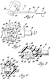
- a motion transmitting remote control assembly for transmitting motion in a curved path is generally shown at 10.
- the assembly 10 includes guide means generally indicated at 11, the guide means 11 including a conduit 12 having a wiper 14 mounted on the end thereof.
- the conduit 12 is a tube member fixedly mounted for pivotal movement on a flexible conduit, the flexible conduit supporting a flexible core element therein for linear movement therethrough.
- the assembly 10 further includes core means including the flexible core element and a rod member 16 secured to the end thereof.
- the rod member 16 is movably supported by the tube member 12 and wiper 14 and extends therefrom to provide a variable extending length of the rod member 16 between the wiper 14 and one end 18 of the rod member 16.
- the rod member 16 is supported within the tube member 12 for reciprocating movement to provide a variable extending length of the rod member 16.
- the wiper 14 includes an opening 20 therethrough, the rod member 16 extending through the opening 20. The wiper 14 prevents foreign particles from entering the tube member 12 which would inhibit the free linear motion of the rod member 16 within the tube member 12.
- a molded integral terminal member is disposed on the extended length of the rod member 16 for operatively interconnecting the rod member 16 and a control member 24.
- the control member 24 is a lever supported upon a rotatable actuating shaft 26.
- the lever 24 includes a ball pin 27 extending therefrom, as shown in phantom in Figure 4.
- the terminal member 22 includes a pocket 28 for retaining the ball pin 27 therein.
- the pocket 28 defines an axis which is substantially parallel to the axis of rotation defined by the actuating shaft 26 when the terminal member 22 is mounted on the ball pin 27.
- the terminal member 22 further includes retaining means 30 for retaining a portion of the ball pin 27 within the pocket 28 and a plurality of slots 32 extending from the pocket 28 substantially to the outer surface of the terminal member 22.
- the slots 32 are parallel to the axis of the pocket 28 so as to divide the terminal member 22 into a plurality of portions.
- the assembly 10 is characterized by the terminal member 22 including integral belt means, generally indicated at 34, connecting at least two of the portions defined by the slots 32 and extending across at least one of the slots 32 for restraining the outward flexure of the connected portions.
- the belt means 34 includes two belts 34 extending between and interconnecting two outward portions 36 disposed on opposite sides of the intermediate portions 38, the portions 36 and 38 being defined by the slots 32.
- the belts 34 extend across the slots 32 on either side of the intermediate portions 38.
- the belts 34 include first sections 40 extending from the outward portions 36 and an elongated second section 42 extending therebetween.
- the elongated second sections 42 are spaced from the outer surface of each intermediate portion 38.
- the first sections 40 extend outwardly from each outward portion 36 of the terminal member 22 and are interconnected by the integral elongated second sections 42.
- the belts 34 provide a bridge which interconnects the outward portions 36 about each pair of slots 32 and are specifically rigid so as to control the outward flexure of the outward portions 36.
- the terminal member 22 includes two pair of slots 32 disposed opposite to one another on opposite sides of the pocket 28 to define two of the intermediate portions 38, the intermediate portions 38 being disposed opposite to one another about the pocket 28.
- the outward portions 36 are defined by two oppositely disposed outward and integral portions 36 extending about the pocket 28 with one end of the outward portions 36 being adjacent to one of the intermediate portions 38 and being connected by one of the belts 34. The other end of the outward portions 36 are adjacent the other of the intermediate portions 38 and connected by the other of the belts 34.
- Each pair of slots 32 are aligned with one another so as to be disposed in spaced parallel planes, as shown in Figure 2.
- each of the intermediate portions 38 includes a flat portion 44 adjacent each of the slots 32.
- the outer surface of each of the intermediate portions 38 further include an outwardly curved portion 46 extending between the flat portions 44 and spaced from the adjacent belt 34.
- the terminal member 22 includes a neck portion 48.
- the rod member 16 has an end portion fixedly secured within the neck portion 48 which defines the line of force.
- the line of force is perpendicular relative to the axis defined by the pocket 28.
- the rod member 16 includes an annular recessed portion 50.
- the neck portion 48 includes an annular projection 52 which engages the recessed portion 50 of the rod member thereby retaining the end portion 18 of the rod member 16 within the terminal member 22.
- the rod member 16 provides linear force which is perpendicular to the axis about which the terminal member 22 rotates relative to the lever 24. This relationship of the line of force defined by the rod member 16 and the axis of rotation defined by the pocket 28 results in stresses causing flexure of the outward portions 36.
- the belts 34 of the instant invention interconnects the outward portions 36 about each pair of slots 32 and intermediate portions 38 to control the outward flexure of the outward portions 36 during the reciprocating movement of the rod member 26 so as to retain the terminal member 22 upon the ball pin 27 of the lever 24.
- the pocket 28 includes an internal substantially hemispherical portion 54 and an external cylindrical portion 56.
- the pocket 28 further includes a frustoconical portion 58 therebetween.
- a circumferential edge portion 60 is between the hemispherical portion 54 and the frustoconical portion 58.
- the restraining means includes a lip 30 extending into the pocket 28 from the circumferential edge 60 wherein each lip 30 extends into the pocket 28 from each of the enclosed intermediate portion 38.
- the lips 30 extend between each of the enclosed slots 32.
- the slots 32 about each intermediate portion 38 allows for sufficient flexibility of the intermediate portions 38 to allow for the insertion of the ball pin 27 into the hemispherical portion 54 of the pocket 28.
- the belts 34 provide sufficient restraint of the flexibility of the outward portions 36 to retain the ball pin 27 within the pocket 28 during reciprocating movement of the rod member 16.
- the pocket 28 includes a groove 66 in the interior thereof disposed on a line parallel relative to the line of force defined by the rod member 16. Lubricant can be disposed within the groove 66 to lubricate the surfaces of the ball pin and the pocket 28.
- the terminal member 22 is an integral molded member of organic polymeric material. During the molding process of the terminal member 22, a mandrel may be used to form the pocket 28. During the molding process the mandrel may form a smaller pocket 68 within the pocket 28.
- the belts 34 provide a high load- carrying ability to the pocket 28 and to the terminal member 22. Therefore, the instant invention is well adapted for uses such as with push- pull assemblies of manual transmissions. Additionally, the spacing between the elongated second portions 42 of the belts 34 and the curved outer surface 46 of each intermediate portion 38 allows for an insertion of a U-shaped clip to lock the ball pin within the pocket 28. Alternatively, other means besides a U-shaped clip may be used as auxiliary retaining means for retaining the ball pin within the pocket 28.
Landscapes
- Engineering & Computer Science (AREA)
- General Engineering & Computer Science (AREA)
- Mechanical Engineering (AREA)
- Health & Medical Sciences (AREA)
- Oral & Maxillofacial Surgery (AREA)
- Pivots And Pivotal Connections (AREA)
- Flexible Shafts (AREA)
- Table Devices Or Equipment (AREA)
- Pens And Brushes (AREA)
- Mechanical Control Devices (AREA)
- Position Input By Displaying (AREA)
- Transmission Devices (AREA)
Claims (12)
Priority Applications (1)
| Application Number | Priority Date | Filing Date | Title |
|---|---|---|---|
| AT83303682T ATE32126T1 (de) | 1982-06-28 | 1983-06-27 | Bowdenzug mit anschlusselement in form einer kugelgelenkpfanne. |
Applications Claiming Priority (2)
| Application Number | Priority Date | Filing Date | Title |
|---|---|---|---|
| US06/392,516 US4499785A (en) | 1982-06-28 | 1982-06-28 | Molded ball socket terminal (connecting belts) |
| US392516 | 1999-09-09 |
Publications (3)
| Publication Number | Publication Date |
|---|---|
| EP0098131A2 EP0098131A2 (de) | 1984-01-11 |
| EP0098131A3 EP0098131A3 (en) | 1985-03-06 |
| EP0098131B1 true EP0098131B1 (de) | 1988-01-20 |
Family
ID=23550906
Family Applications (1)
| Application Number | Title | Priority Date | Filing Date |
|---|---|---|---|
| EP83303682A Expired EP0098131B1 (de) | 1982-06-28 | 1983-06-27 | Bowdenzug mit Anschlusselement in Form einer Kugelgelenkpfanne |
Country Status (6)
| Country | Link |
|---|---|
| US (1) | US4499785A (de) |
| EP (1) | EP0098131B1 (de) |
| JP (1) | JPS5958217A (de) |
| AT (1) | ATE32126T1 (de) |
| CA (1) | CA1203696A (de) |
| DE (1) | DE3375421D1 (de) |
Families Citing this family (19)
| Publication number | Priority date | Publication date | Assignee | Title |
|---|---|---|---|---|
| US4625579A (en) * | 1984-11-28 | 1986-12-02 | Teleflex Incorporated | Capped core element terminal |
| DE3715360A1 (de) * | 1987-05-08 | 1988-12-01 | Lemfoerder Metallwaren Ag | Molekulargelenk fuer achsstreben, lenker oder dergleichen in kraftfahrzeugen |
| DE8811059U1 (de) * | 1988-09-01 | 1989-12-28 | Robert Bosch Gmbh, 7000 Stuttgart | Kugelgelenk, insbesondere für Verstelleinrichtungen bei Scheinwerfern von Kraftfahrzeugen |
| JPH0240118U (de) * | 1988-09-09 | 1990-03-19 | ||
| US4947704A (en) * | 1989-08-24 | 1990-08-14 | Babcock Industries Inc. | Snap on strand assembly |
| US5241879A (en) * | 1990-07-13 | 1993-09-07 | Teleflex Incorporated | Snap-on fastening device |
| FR2670255A1 (fr) * | 1990-12-11 | 1992-06-12 | Systeme Sa | Biellette d'accouplement. |
| MX9203982A (es) * | 1991-08-30 | 1993-02-01 | Xerox Corp | Conjunto de eje impulsor, flexible, moldeado de una sola pieza. |
| US5641235A (en) * | 1995-06-07 | 1997-06-24 | Dana Corporation | Composite encased ball joint |
| US5653548A (en) * | 1996-02-07 | 1997-08-05 | Illinois Tool Works Inc. | Method and apparatus for a ball and socket joint |
| US5682798A (en) * | 1996-04-30 | 1997-11-04 | Teleflex Incorporated | Universal core terminal |
| US5833383A (en) * | 1997-07-23 | 1998-11-10 | Avm, Inc. | Ball socket connector |
| ES2191234T3 (es) | 1997-09-12 | 2003-09-01 | Bollhoff Gmbh | Acoplamiento por enchufe. |
| US5934150A (en) * | 1998-01-05 | 1999-08-10 | Teleflex Incorporated | Remote control assembly having a locking terminal |
| US6758622B2 (en) * | 2001-02-16 | 2004-07-06 | Burton Technologies Llc | Ball socket with improved pull-out force resistance |
| US20060039748A1 (en) * | 2002-06-07 | 2006-02-23 | Ruhlander Gregory P | Arrangement for connecting a rod end to a headed pin and method of manufacture |
| US20040113116A1 (en) * | 2002-11-20 | 2004-06-17 | London Larry R. | Remote valve actuator |
| DE202007017248U1 (de) * | 2007-12-10 | 2009-04-16 | Ramsauer, Dieter | Adapter zur Anlenkung einer Stange wie Verriegelungsstange eines Stangenverschlusses an einen Hebel wie Betätigungshebel des Stangenverschlusses |
| DE102014105956B4 (de) * | 2014-04-29 | 2023-11-09 | Brose Fahrzeugteile Se & Co. Kommanditgesellschaft, Bamberg | Linearantrieb für ein Verstellelement eines Kraftfahrzeugs |
Family Cites Families (7)
| Publication number | Priority date | Publication date | Assignee | Title |
|---|---|---|---|---|
| US2323624A (en) * | 1941-08-25 | 1943-07-06 | Myron R Schall | Swivel |
| DE1921769C3 (de) * | 1969-04-29 | 1974-07-04 | Springfix-Befestigungstechnik Gmbh, 7335 Salach | Kugelgelenk |
| CH506722A (de) * | 1969-11-14 | 1971-04-30 | Fibotema Ag | Kugelpfanne aus Kunststoff |
| DE2057513A1 (de) * | 1970-11-23 | 1972-06-15 | Elastrogran Gmbh | Kugelgelenk |
| FR2345614A2 (fr) * | 1976-03-25 | 1977-10-21 | Itw De France | Cuvette d'articulation a genouillere |
| US4327600A (en) * | 1980-06-02 | 1982-05-04 | Teleflex Incorporated | Remote control (connector O-ring) |
| DE3119061A1 (de) * | 1980-09-10 | 1982-04-29 | Springfix-Befestigungstechnik Gmbh, 7335 Salach | Einstueck aus einem kunststoff gespritzte kugelpfanne fuer ein kugelgelenk |
-
1982
- 1982-06-28 US US06/392,516 patent/US4499785A/en not_active Expired - Fee Related
-
1983
- 1983-06-27 JP JP58115737A patent/JPS5958217A/ja active Pending
- 1983-06-27 CA CA000431200A patent/CA1203696A/en not_active Expired
- 1983-06-27 EP EP83303682A patent/EP0098131B1/de not_active Expired
- 1983-06-27 DE DE8383303682T patent/DE3375421D1/de not_active Expired
- 1983-06-27 AT AT83303682T patent/ATE32126T1/de not_active IP Right Cessation
Also Published As
| Publication number | Publication date |
|---|---|
| DE3375421D1 (en) | 1988-02-25 |
| ATE32126T1 (de) | 1988-02-15 |
| EP0098131A3 (en) | 1985-03-06 |
| US4499785A (en) | 1985-02-19 |
| EP0098131A2 (de) | 1984-01-11 |
| JPS5958217A (ja) | 1984-04-03 |
| CA1203696A (en) | 1986-04-29 |
Similar Documents
| Publication | Publication Date | Title |
|---|---|---|
| EP0098131B1 (de) | Bowdenzug mit Anschlusselement in Form einer Kugelgelenkpfanne | |
| US4694705A (en) | Molded terminal for remote control assembly (lollipop) | |
| US4581953A (en) | Molded terminal with vibration dampener pocket | |
| US5855519A (en) | Ball fixed type constant velocity joint having low rotational backlash | |
| US5265495A (en) | Isolated shifter terminal assembly | |
| CA2061933C (en) | Rotatable slider body | |
| US5522280A (en) | Connecting links for windshield wipers and method for fabricating the link | |
| CA2175304C (en) | Core terminal for motion-transmitting remote control assembly | |
| US4333361A (en) | Remote control (swivel joint) | |
| US5896778A (en) | Operating lever device for manual transmissions for motor vehicles | |
| WO1982003110A1 (en) | Split pulley | |
| EP1089155A2 (de) | Positionierbare Pedaleinheit mit Zahnrädern in einer Kammer | |
| US5048996A (en) | Universal connector for retaining and linking members | |
| US5073145A (en) | Joint movable in all directions, especially for linkages and cardan shafts | |
| US4565107A (en) | Ball through-passage for the gearshifting lever of a motor vehicle | |
| US4590819A (en) | Motion transmitting remote control assembly molded terminal connector | |
| US6893010B2 (en) | Sleeve, particularly a rod sleeve | |
| EP0500248A1 (de) | Drehverbindung | |
| KR100204887B1 (ko) | 컨트롤 케이블의 결합구조 | |
| US5014569A (en) | Motion transmitting remote control assembly and method for making same | |
| JPS6365540B2 (de) | ||
| CA1201041A (en) | Molded terminal for remote control assembly (lollipop) | |
| GB2122714A (en) | Protective routing sleeve for hose assemblies | |
| US20030040367A1 (en) | Tripod joint | |
| EP0098132A2 (de) | Angeformtes Endstück mit Vibrationsdämpfungsausnehmung |
Legal Events
| Date | Code | Title | Description |
|---|---|---|---|
| PUAI | Public reference made under article 153(3) epc to a published international application that has entered the european phase |
Free format text: ORIGINAL CODE: 0009012 |
|
| AK | Designated contracting states |
Designated state(s): AT BE CH DE FR GB IT LI LU NL SE |
|
| PUAL | Search report despatched |
Free format text: ORIGINAL CODE: 0009013 |
|
| AK | Designated contracting states |
Designated state(s): AT BE CH DE FR GB IT LI LU NL SE |
|
| 17P | Request for examination filed |
Effective date: 19850226 |
|
| GRAA | (expected) grant |
Free format text: ORIGINAL CODE: 0009210 |
|
| AK | Designated contracting states |
Kind code of ref document: B1 Designated state(s): AT BE CH DE FR GB IT LI LU NL SE |
|
| PG25 | Lapsed in a contracting state [announced via postgrant information from national office to epo] |
Ref country code: NL Effective date: 19880120 Ref country code: AT Effective date: 19880120 |
|
| REF | Corresponds to: |
Ref document number: 32126 Country of ref document: AT Date of ref document: 19880215 Kind code of ref document: T |
|
| PG25 | Lapsed in a contracting state [announced via postgrant information from national office to epo] |
Ref country code: SE Effective date: 19880131 |
|
| REF | Corresponds to: |
Ref document number: 3375421 Country of ref document: DE Date of ref document: 19880225 |
|
| ITF | It: translation for a ep patent filed | ||
| ET | Fr: translation filed | ||
| NLV1 | Nl: lapsed or annulled due to failure to fulfill the requirements of art. 29p and 29m of the patents act | ||
| PG25 | Lapsed in a contracting state [announced via postgrant information from national office to epo] |
Ref country code: GB Effective date: 19880627 |
|
| PG25 | Lapsed in a contracting state [announced via postgrant information from national office to epo] |
Ref country code: LU Free format text: LAPSE BECAUSE OF NON-PAYMENT OF DUE FEES Effective date: 19880630 Ref country code: LI Effective date: 19880630 Ref country code: CH Effective date: 19880630 |
|
| PLBE | No opposition filed within time limit |
Free format text: ORIGINAL CODE: 0009261 |
|
| STAA | Information on the status of an ep patent application or granted ep patent |
Free format text: STATUS: NO OPPOSITION FILED WITHIN TIME LIMIT |
|
| BERE | Be: lapsed |
Owner name: TELEFLEX INC. Effective date: 19880630 |
|
| 26N | No opposition filed | ||
| GBPC | Gb: european patent ceased through non-payment of renewal fee | ||
| PG25 | Lapsed in a contracting state [announced via postgrant information from national office to epo] |
Ref country code: FR Free format text: LAPSE BECAUSE OF NON-PAYMENT OF DUE FEES Effective date: 19890228 |
|
| REG | Reference to a national code |
Ref country code: CH Ref legal event code: PL |
|
| PG25 | Lapsed in a contracting state [announced via postgrant information from national office to epo] |
Ref country code: DE Effective date: 19890301 |
|
| REG | Reference to a national code |
Ref country code: FR Ref legal event code: ST |
|
| PG25 | Lapsed in a contracting state [announced via postgrant information from national office to epo] |
Ref country code: BE Effective date: 19890630 |