EP0098211A1 - Gehäuse mit selbsttätig gesteuerter Klappe für Kanal, wie Rauchabzugkanal, von offenen Kaminen - Google Patents
Gehäuse mit selbsttätig gesteuerter Klappe für Kanal, wie Rauchabzugkanal, von offenen Kaminen Download PDFInfo
- Publication number
- EP0098211A1 EP0098211A1 EP83401295A EP83401295A EP0098211A1 EP 0098211 A1 EP0098211 A1 EP 0098211A1 EP 83401295 A EP83401295 A EP 83401295A EP 83401295 A EP83401295 A EP 83401295A EP 0098211 A1 EP0098211 A1 EP 0098211A1
- Authority
- EP
- European Patent Office
- Prior art keywords
- valve
- axis
- jack
- carriage
- sliding element
- Prior art date
- Legal status (The legal status is an assumption and is not a legal conclusion. Google has not performed a legal analysis and makes no representation as to the accuracy of the status listed.)
- Withdrawn
Links
- 239000003546 flue gas Substances 0.000 title abstract description 3
- UGFAIRIUMAVXCW-UHFFFAOYSA-N Carbon monoxide Chemical compound [O+]#[C-] UGFAIRIUMAVXCW-UHFFFAOYSA-N 0.000 title description 2
- 230000000694 effects Effects 0.000 claims description 7
- 238000010438 heat treatment Methods 0.000 claims description 6
- 238000001816 cooling Methods 0.000 claims description 5
- 239000000112 cooling gas Substances 0.000 claims description 2
- 230000002093 peripheral effect Effects 0.000 claims description 2
- 230000006835 compression Effects 0.000 description 1
- 238000007906 compression Methods 0.000 description 1
- 238000006073 displacement reaction Methods 0.000 description 1
- 239000007789 gas Substances 0.000 description 1
- 238000009499 grossing Methods 0.000 description 1
- 206010022000 influenza Diseases 0.000 description 1
- 238000002955 isolation Methods 0.000 description 1
- 239000002184 metal Substances 0.000 description 1
Images

Classifications
-
- F—MECHANICAL ENGINEERING; LIGHTING; HEATING; WEAPONS; BLASTING
- F24—HEATING; RANGES; VENTILATING
- F24B—DOMESTIC STOVES OR RANGES FOR SOLID FUELS; IMPLEMENTS FOR USE IN CONNECTION WITH STOVES OR RANGES
- F24B1/00—Stoves or ranges
- F24B1/18—Stoves with open fires, e.g. fireplaces
- F24B1/185—Stoves with open fires, e.g. fireplaces with air-handling means, heat exchange means, or additional provisions for convection heating ; Controlling combustion
- F24B1/189—Stoves with open fires, e.g. fireplaces with air-handling means, heat exchange means, or additional provisions for convection heating ; Controlling combustion characterised by air-handling means, i.e. of combustion-air, heated-air, or flue-gases, e.g. draught control dampers
- F24B1/1895—Stoves with open fires, e.g. fireplaces with air-handling means, heat exchange means, or additional provisions for convection heating ; Controlling combustion characterised by air-handling means, i.e. of combustion-air, heated-air, or flue-gases, e.g. draught control dampers flue-gas control dampers
-
- F—MECHANICAL ENGINEERING; LIGHTING; HEATING; WEAPONS; BLASTING
- F23—COMBUSTION APPARATUS; COMBUSTION PROCESSES
- F23L—SUPPLYING AIR OR NON-COMBUSTIBLE LIQUIDS OR GASES TO COMBUSTION APPARATUS IN GENERAL ; VALVES OR DAMPERS SPECIALLY ADAPTED FOR CONTROLLING AIR SUPPLY OR DRAUGHT IN COMBUSTION APPARATUS; INDUCING DRAUGHT IN COMBUSTION APPARATUS; TOPS FOR CHIMNEYS OR VENTILATING SHAFTS; TERMINALS FOR FLUES
- F23L11/00—Arrangements of valves or dampers after the fire
- F23L11/005—Arrangements of valves or dampers after the fire for closing the flue during interruption of burner function
-
- F—MECHANICAL ENGINEERING; LIGHTING; HEATING; WEAPONS; BLASTING
- F23—COMBUSTION APPARATUS; COMBUSTION PROCESSES
- F23J—REMOVAL OR TREATMENT OF COMBUSTION PRODUCTS OR COMBUSTION RESIDUES; FLUES
- F23J2213/00—Chimneys or flues
- F23J2213/50—Top cover
Definitions
- the subject of the invention is a sheath intended especially but not exclusively to be placed between the outlet of the chimney of the chimneys and the first bushel of the flue.
- valve mounted at this point pivoting about a horizontal axis between a closed position and an open position of the draft.
- This valve and its axis are installed either directly in the masonry at the birth of the flue after the drain, or in a simple metal frame embedded in the masonry.
- This classic valve is manually operated for opening and closing. However, for obvious safety reasons, the valve should only be closed when the fire is completely out. Since, after a vigil, the fire actually only goes out during the night, there is a tendency to leave the valve open so that, after the fire has gone out, the hot air from the room is evacuated through the chimney and that the cold morning air enters very easily.
- the main object of the invention is to provide a valve sheath whose valve can be operated by hand if desired, but can also operate automatically upon opening and especially upon closing; in other words, the valve of a sheath according to the invention is automatically put in the closed position when the fire has gone out in the hearth or as soon as it has cooled considerably to the point of extinguishing soon.
- a sheath according to the invention comprises a frame designed to contain and guide in rotation the end parts of an axis to which a closing valve is fixed; a housing is provided on at least one side of this frame outside the volume swept by the valve; an automatic control device comprising a cylinder sensitive to heat against the action of a return spring is disposed in this housing and coupled with an end part of the axis of the valve in order to pivot the latter in the direction of opening as a result of heating and in the direction of closing as a result of cooling.
- Any heat-sensitive cylinder sufficiently expandable when it is heated, can be used in a sheath according to the invention.
- An example of such a heat-sensitive cylinder can be found in this sheath, referring to the 1st French addition certificate No. 81 13404. But other cylinders may also be suitable as is will show further.
- the sheath of the invention comprises two frames with combined geometric axes, spaced in an axial direction, and cooperating with each other so as to limit between them an annular, rectangular volume, one of the sides of which constitutes the housing of the automatic control device.
- One of the frames preferably the lower frame in the position of use of the sheath, is used for mounting the valve; it is advantageous to choose as the housing of the control device one of the sides of the annular volume where one of the extreme parts of the axis of the valve is located.
- This end part of the axis has a non-revolution profile and it is coupled, by simple interlocking, with a rotary bar, at least one wing of which is engaged in a slot of a sliding element. The latter is pushed in the direction of opening of the valve by the heat-sensitive cylinder and in the direction of closing of the valve by the return spring.
- the sliding element is provided with a cable making it possible to pull it to its valve opening position when the jack is not heated.
- a means for locking the valve in the open position when the sliding element has been moved using the cable and it is also provided, in an exemplary embodiment of the invention, that the heat-sensitive cylinder has a greater stroke -to- the opening stroke of the valve, which allows it to make inactive the locking means so that, during cooling, the sliding element closes the valve.
- the automatic control device comprises a sliding carriage on which is mounted and guided in movement the sliding element.
- This last element has a slot in which is engaged a wing of the operating bar of the valve axis; it is connected to the smoothing carriage q by a spring and a locking actuator actuated by a spring is arranged between the carriage and the sliding element to lock the latter relative to the carriage, when this element occupies its valve opening position.
- the sliding carriage is provided at one end with a traction cable and at the opposite end it is pressed against a cylinder sensitive to heat under the effect of a return spring.
- This carriage has a stroke greater than that of the sliding element when it is pushed by the jack which heats up and, during this stroke, it pushes the locking pallet to a rest position, so that, during the cooling of the cylinder, the return spring returns the carriage and the sliding element to their rest position which corresponds to the closing of the valve.
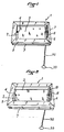
- a sheath 1 comprises a first frame 2 in which a valve 3 is pivotally mounted about an axis 4 between a closed position ( Figure 1) and an open position ( Figure 2).
- This sheath 1 further comprises a second frame 5 identical to the frame 2 and spaced from the latter in an axial direction along their common geometrical axis, so as to form between them a volume 6.
- a volume 6 In FIGS. 1 and 2 one of the short sides of the second frame 5 is torn off to show the volume 6. The latter is open on the passage where the valve 3 is located.
- the two frames 2 and 5 are superimposed and rest on each other by their outer peripheral edge 7.
- the latter is mounted, for sliding, inside a fixed guide body 14 and it is subjected on the one hand to the thrust d 'a cylinder 15 sensitive to heat which moves it to a position in which the bar 10 puts the valve 3 in the open position, on the other hand to the opposing force of a return spring 16 which tends to bring this element sliding 13 to a position in which the bar 10 puts the valve 3 in the closed position.
- a cable 17 is attached to the sliding element 13 either directly as in the example in FIGS. 5 to 7, or indirectly as in the example in FIGS. 3 and 4, so that one can, by pulling by hand on this cable 17, put the valve 3 in the open position.
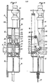
- FIGS. 3 and 4 describe a preferred embodiment of a device 8 for automatic control of the valve 3.
- the fixed body 14 has two opposite side walls 14A, 14B between which the axis 9 is supported so that it can rotate at least 90 °.
- a first pair of 18 of longitudinal guide grooves and a second pair 19 of longitudinal grooves are hollowed out; these two pairs 18 and 19 are spaced apart from each other in the longitudinal direction.
- the grooves 18, 19 serve to guide in sliding a sliding carriage 20 which has one end 21 to which the cable 17 is attached and to which is hooked one end of the return spring 16.
- the other end of this spring 16 is hooked to the fixed body 14.
- the second end 22 of the carriage 20 is pressed by the effect of the spring 16 against a sensitive jack 15. heat. composed of two units mounted in series and supported by the fixed body 14.
- a transverse axis 26 around which is freely rotatably mounted a locking pallet 27 which has a first end 27A intended to meet a stop face 13A provided on the sliding element 13.
- the pallet 27 has a second end 27B intended to be encountered and pushed back by a cam 28 provided on a longitudinal wall 29 which forms part of the carriage 20.
- a return spring 30 wound around the axis 26 applies the first end 27A against the element 13 .
- the jack 15 In the rest position of the device described here, visible in FIGS. 3 and 4, the jack 15 is in the state of retraction and the springs 16 and 25 retain the sliding carriage 20 and the sliding element 13 at the end of their close travel. of the jack 15.
- a wing 10A of the bar 10 is engaged dans.la slot 12 of sliding isolation 13, the valve 3 being in the closed position.
- a fixed transverse pin 31 which serves as a stop for the bar 10 when the latter has pivoted sufficiently in the clockwise direction indicated by an arrow F in FIG. 4 so that the valve 3 found in its fully open position.
- the slot 12 has an end portion 12A enlarged to the dimension of the bar 10 with an end face inclined according to the position thereof which corresponds to the closing of the flap. Then a ramp 12B acts during the movement of the element 13 on a wing 10A to rotate the bar 10 and put it in the open position of the flap 3, after which the slot 12 has an elongated part 12C narrowed in width to l size of the bar 10 after pivoting 90 °. The narrowed portion 12C maintains over its entire length the bar 10 and the flap 3 in the open position.
- the jack 15 is chosen to produce this effect of automatic opening of the valve 3 when the temperature in the sheath 1 goes from 25 ° to 35 ° C.
- the shutter 3 can be opened manually by acting on the cable 17 to which is attached a chain 32 provided with a handle 33 ( Figures 1 and 2).
- the sliding element 13 is moved directly and the slot 12 causes the flap 3 to open by its profile.
- the cylinder 1 5 holds the element 13 and moves it even further by heating up further, the valve 3 being held in the open state.
- traction on the cable 17 causes the carriage 20 and the the element 13 by means of the springs 25 until the cam 28 meets the end 27B of the locking pallet 27 whose end 27A then has the possibility of pivoting and of being placed in front of the face of stop 13A of the element 13.
- the cable 17 can be released; the valve 3 remains in the open state since the sliding element 13 cannot go back because of the locking pallet 27 which retains it.
- the jack 15 heats up, it meets the carriage 20 and pushes it beyond this position while the springs 25 are elongating and the grooves 23, 24 slide relative to the element 13. During this movement the cam 28 exceeds the branch 27B.
- the spring 16 is a compression spring which relaxes; when the inclined face of the end part 12A meets a wing 10A of the bar 10, it rotates it by 90 ° and closes the valve 3.
- the spring 16 is a tension spring which tightens; when the sliding element 13 is encountered and driven by the terminal end of the grooves 23, 24, the cam 28 meets the branch 27B of the pallet 27 and it pivots the latter against its return spring 30 in a direction which moves the l opposite end 27A of the sliding element 13. The latter therefore accompanies the carriage 20 to its initial position visible in FIG. 4, by closing the valve 3.
- the sheath of the invention is not limited to the preferred use. which has been described above. We can install it. sheath of the invention in any gas passage duct which must be able to circulate freely in the event of a rise in temperature, such as in horticultural greenhouses during sunshine hours, or in the garbage can sheaths in the event of heating, or in the flue gas exhaust flues in case of fire. etc ..., the sheath having the advantage of closing the conduit after cooling, which is particularly useful not only in greenhouses but in most uses.
Landscapes
- Engineering & Computer Science (AREA)
- Chemical & Material Sciences (AREA)
- Combustion & Propulsion (AREA)
- Mechanical Engineering (AREA)
- General Engineering & Computer Science (AREA)
- Mechanically-Actuated Valves (AREA)
- Fire-Extinguishing By Fire Departments, And Fire-Extinguishing Equipment And Control Thereof (AREA)
Applications Claiming Priority (2)
| Application Number | Priority Date | Filing Date | Title |
|---|---|---|---|
| FR8211496 | 1982-06-30 | ||
| FR8211496A FR2529637B1 (fr) | 1982-06-30 | 1982-06-30 | Gaine avec clapet a commande automatique pour conduit tel que conduit de fumee des cheminees a atres |
Publications (1)
| Publication Number | Publication Date |
|---|---|
| EP0098211A1 true EP0098211A1 (de) | 1984-01-11 |
Family
ID=9275559
Family Applications (1)
| Application Number | Title | Priority Date | Filing Date |
|---|---|---|---|
| EP83401295A Withdrawn EP0098211A1 (de) | 1982-06-30 | 1983-06-22 | Gehäuse mit selbsttätig gesteuerter Klappe für Kanal, wie Rauchabzugkanal, von offenen Kaminen |
Country Status (2)
| Country | Link |
|---|---|
| EP (1) | EP0098211A1 (de) |
| FR (1) | FR2529637B1 (de) |
Citations (5)
| Publication number | Priority date | Publication date | Assignee | Title |
|---|---|---|---|---|
| CH364882A (de) * | 1957-06-13 | 1962-10-15 | Von Blanquet Otto Dr | Abgassicherheitseinrichtung für gasbeheizte Geräte |
| FR1429027A (fr) * | 1965-03-31 | 1966-02-18 | Clapet de gaz d'échappement incorporé dans une hotte s'évasant vers le bas, notamment pour appareils de chauffage au gaz | |
| DE1784091A1 (de) * | 1968-07-06 | 1971-07-22 | Trox Gmbh Geb | Feuerschutzklappe,insbesondere zum Einbau in Lueftungskanaele von Schiffen |
| FR2376935A1 (fr) * | 1977-01-06 | 1978-08-04 | Sort Andre | Trappe de cheminee |
| FR2509440A2 (fr) * | 1981-07-08 | 1983-01-14 | Dufois Gilbert | Dispositif permettant d'ouvrir et de fermer automatiquement, progressivement, et a distance, les volets des registres des feux ouverts ou fermes existants ou a construire |
-
1982
- 1982-06-30 FR FR8211496A patent/FR2529637B1/fr not_active Expired
-
1983
- 1983-06-22 EP EP83401295A patent/EP0098211A1/de not_active Withdrawn
Patent Citations (5)
| Publication number | Priority date | Publication date | Assignee | Title |
|---|---|---|---|---|
| CH364882A (de) * | 1957-06-13 | 1962-10-15 | Von Blanquet Otto Dr | Abgassicherheitseinrichtung für gasbeheizte Geräte |
| FR1429027A (fr) * | 1965-03-31 | 1966-02-18 | Clapet de gaz d'échappement incorporé dans une hotte s'évasant vers le bas, notamment pour appareils de chauffage au gaz | |
| DE1784091A1 (de) * | 1968-07-06 | 1971-07-22 | Trox Gmbh Geb | Feuerschutzklappe,insbesondere zum Einbau in Lueftungskanaele von Schiffen |
| FR2376935A1 (fr) * | 1977-01-06 | 1978-08-04 | Sort Andre | Trappe de cheminee |
| FR2509440A2 (fr) * | 1981-07-08 | 1983-01-14 | Dufois Gilbert | Dispositif permettant d'ouvrir et de fermer automatiquement, progressivement, et a distance, les volets des registres des feux ouverts ou fermes existants ou a construire |
Also Published As
| Publication number | Publication date |
|---|---|
| FR2529637A1 (fr) | 1984-01-06 |
| FR2529637B1 (fr) | 1986-02-28 |
Similar Documents
| Publication | Publication Date | Title |
|---|---|---|
| EP2258232B1 (de) | Vorrichtung zur Haarbehandlung und Haarbehandlungsgerät, das eine solche Vorrichtung umfasst | |
| FR2530132A1 (fr) | Seche-cheveux muni de soupapes pour le reglage du flux d'air | |
| CA2674927A1 (fr) | Inverseur de poussee translatable pour moteur a reaction | |
| EP0190976A1 (de) | Schliesseinrichtung für Fahrzeugtüren | |
| EP0098211A1 (de) | Gehäuse mit selbsttätig gesteuerter Klappe für Kanal, wie Rauchabzugkanal, von offenen Kaminen | |
| EP0084016B1 (de) | Direkte Rauchgasabführung bei Heizeinrichtungen mit abgeschlossenem Verbrennungsofen | |
| EP2152116B1 (de) | Haarglättungsvorrichtung | |
| FR3004528B1 (fr) | Recuperateur de chaleur des fumees d'un poele a bois | |
| EP0539300B1 (de) | Türverschlussvorrichtung für einen isolierten Raum | |
| FR2694578A1 (fr) | Sèche linge avec bloc condenseur. | |
| FR2721096A1 (fr) | Dispositif d'alimentation et d'allumage automatique d'une chaudière avec du bois de chauffage. | |
| FR2851445A1 (fr) | Gril a retournement simplifie | |
| FR2543210A1 (fr) | Volet mobile destine a venir se placer derriere une fenetre d'un batiment | |
| FR2608102A1 (fr) | Dispositif d'actionnement d'un volet d'obturation | |
| EP2152115A2 (de) | Haarkräftigungsmittel | |
| FR2643978A1 (fr) | Cheminee a parties escamotables | |
| FR2891612A1 (fr) | Conduit de desenfumage a soufflerie et a volets retractables | |
| FR2539217A2 (fr) | Gaine avec clapet a commande automatique pour conduit tel que conduit de fumee des cheminees a atres | |
| FR2537703A1 (fr) | Procede et dispositif de commande d'une cheminee a foyer ouvert | |
| CA2168893C (fr) | Bras de retenu pliable avec declencheur automatique et serrure pour le tir a l'arc | |
| FR2764365A1 (fr) | Detrompeur de manoeuvre pour cheminee a porte frontale | |
| FR2690478A1 (fr) | Foyer de cheminée à porte pivotante et escamotable. | |
| EP0754920A1 (de) | Vorrichtung zum Öffnen oder Schliessen einer Tür für einen Raum und Backofen mit einer solchen Vorrichtung | |
| FR2643413A1 (fr) | Dispositif de trappe basculante | |
| FR2638908A1 (fr) | Coffret de securite permettant de commander l'arret et la remise en marche d'un moteur a commande electrique |
Legal Events
| Date | Code | Title | Description |
|---|---|---|---|
| PUAI | Public reference made under article 153(3) epc to a published international application that has entered the european phase |
Free format text: ORIGINAL CODE: 0009012 |
|
| 17P | Request for examination filed |
Effective date: 19830627 |
|
| AK | Designated contracting states |
Designated state(s): AT BE CH DE GB IT LI LU NL SE |
|
| STAA | Information on the status of an ep patent application or granted ep patent |
Free format text: STATUS: THE APPLICATION IS DEEMED TO BE WITHDRAWN |
|
| 18D | Application deemed to be withdrawn |
Effective date: 19841205 |
|
| RIN1 | Information on inventor provided before grant (corrected) |
Inventor name: LACOUR, ANDRE Inventor name: DUFOIS, GILBERT, ANDRE |