EP0098254A2 - Schussfadenspeicher für Düsenwebmaschinen - Google Patents
Schussfadenspeicher für Düsenwebmaschinen Download PDFInfo
- Publication number
- EP0098254A2 EP0098254A2 EP83850181A EP83850181A EP0098254A2 EP 0098254 A2 EP0098254 A2 EP 0098254A2 EP 83850181 A EP83850181 A EP 83850181A EP 83850181 A EP83850181 A EP 83850181A EP 0098254 A2 EP0098254 A2 EP 0098254A2
- Authority
- EP
- European Patent Office
- Prior art keywords
- weft
- reservoir
- control pin
- cam
- control
- Prior art date
- Legal status (The legal status is an assumption and is not a legal conclusion. Google has not performed a legal analysis and makes no representation as to the accuracy of the status listed.)
- Withdrawn
Links
Images



Classifications
-
- D—TEXTILES; PAPER
- D03—WEAVING
- D03D—WOVEN FABRICS; METHODS OF WEAVING; LOOMS
- D03D47/00—Looms in which bulk supply of weft does not pass through shed, e.g. shuttleless looms, gripper shuttle looms, dummy shuttle looms
- D03D47/34—Handling the weft between bulk storage and weft-inserting means
-
- D—TEXTILES; PAPER
- D03—WEAVING
- D03D—WOVEN FABRICS; METHODS OF WEAVING; LOOMS
- D03D47/00—Looms in which bulk supply of weft does not pass through shed, e.g. shuttleless looms, gripper shuttle looms, dummy shuttle looms
- D03D47/34—Handling the weft between bulk storage and weft-inserting means
- D03D47/36—Measuring and cutting the weft
- D03D47/361—Drum-type weft feeding devices
- D03D47/362—Drum-type weft feeding devices with yarn retaining devices, e.g. stopping pins
-
- D—TEXTILES; PAPER
- D03—WEAVING
- D03D—WOVEN FABRICS; METHODS OF WEAVING; LOOMS
- D03D47/00—Looms in which bulk supply of weft does not pass through shed, e.g. shuttleless looms, gripper shuttle looms, dummy shuttle looms
- D03D47/34—Handling the weft between bulk storage and weft-inserting means
- D03D47/36—Measuring and cutting the weft
- D03D47/361—Drum-type weft feeding devices
- D03D47/362—Drum-type weft feeding devices with yarn retaining devices, e.g. stopping pins
- D03D47/363—Construction or control of the yarn retaining devices
Definitions
- the side of the device closer to the supply source of weft is referred to as “the upstream side” and the side of the device closer to the main jet nozzle is referred to as “the downstream side”.
- control pin leaves its operative zone by disappearing from the periphery of the reservoir drum, and advances into its operative zone by appearing on the periphery of the reservoir drum.
- weft reservoir can well be used for weaving by one sort of weaving, too.
- a magazine 41 is arranged on the outer side of the reservoir drum 1 in a fixed relationship, and a slot 41a is formed in the wall of magazine 41 facing the reservoir drum 1 whilst extending in the axial direction of the reservoir drum 1.
- the first control pin P1 is directed towards the reservoir drum 1 through this slot 41a and its drive cam Cl is encased within the magazine 41.
- Each of the drive cams C1 and C2 completes its one cycle rotation within a period of 0° to 1080° crank angle, weft delivery for the first weft insertion is carried out within a period of 0° to 360 crank angle and weft delivery for the second insertion is carried out within a period of 360 to 720° crank angle, on one weft reservoir. During a period of 720° to 1080 crank angle, weft delivery for insertion is carried out once on the other weft reservoir.
- each of the drive cams C1 and C2 completes its one cycle rotation within a period of 0 to 1440° crank angle and weft delivery for insertion is carried out twice within a period of 0° to 720 crank angle on one weft reservoir.
- weft delivery for insertion is carried out twice on the other weft reservoir.
- a moment (I) in Fig. 2 corresponds to 0° crank angle.
- the first control pin P1 stays standstill at the most advanced position in its operative zone whereas the second control pin P2 has already started to recede from the most advanced position in its operative zone in order to move downstream along an arc path of travel in the axial direction of the reservoir drum 1.
- Reservation of weft for the second insertion has already started on the upstream side of the first control pin P1 and coils of weft for the first insertion are reserved in the area between the first and second control pins P1 and P2.
- a moment (DI) in Fig. 2 corresponds to 180 0 crank angle.
- a moment X in Fig. 2 corresponds to 810 crank angle and shift in condition from this moment corresponds to that from the moment (IV) to the moment (VI).
- the first control pin P1 starts to recede from the most advanced position in the operative zone to travel downstream whereas the second control pin P2 starts to advance from the most receded position in the stand-by zone. Reservation of weft further develops on the upstream side of the first control pin P1.
- the coils of reserved weft are always assigned from the first to second control pin at the same axial position on the reservoir drum whereat the two control pins pass by.
- This similarity in assignment of reserved weft relates to similarity in mode of reservation of weft for the first and second insertions.
- Such similar mode of reservation of weft at different moments relates to similar behaviour of weft during delivery of weft at different moment.
- Uniform insertion can be carried out for every cycle of loom running. This is the:biggest advantage of the present invention.
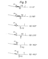
- FIG. 3 The other example of the operation of the weft reservoir in accordance with the present invention is shown in Fig. 3, in which, like the first example, four coils of weft are assumed to correspond to the length of weft for one insertion of weft, black circles indicate coils of weft for the first insertion of weft, and white circles indicate coils of weft for the second insertion of weft.'
- a moment (I) in Fig. 3 corresponds to 0° crank angle.
- the first control pin P1 is located within the operative zone and the second control pin P2 has started to recede from the most advanced position in the operative zone to move downstream along an arc path of travel in the axial direction of the weft reservoir 1. Reservation of weft for the second insertion has already started on the upstream side of the first control pin P1 and coils of weft for the first insertion are held in the area between the two control pins P1 and P2.
- the second control pin P2 has just disappeared from the periphery of the reservoir drum 1. Delivery of weft for the first insertion now starts. Reservation of weft further continues on the upstream side of the first control pin P1 and the coils of weft, which have been held in the area between the first and second control pins, are sequentially delivered due to traction by the main jet nozzle which has started the first insertion of weft.
- a moment (VI) in Fig. 3 corresponds to 450 crank angle.
- the first control pin P1 has reached the most receded position in the stand-by zone and the second control pin P2 remains standstill at the most receded position in the stand-by zone.
- the second insertion of weft starts at this moment.
- the coils of weft which have been held by the first control pin P1 are sequentially delivered due to traction of the main jet nozzle.
- the first control pin P1 has already been registered at the most advanced position in the operative zone and the position of the second control pin P2 is unchanged.
- the second insertion of weft terminates about this moment and reservation of weft for the first insertion of the next cycle has already started on the upstream side of the first control pin Pl.
- This condition is maintained at the moment (IX) in Fig. 3 corres- ponding to 720 crank angle and the above-described reservation of weft further develops.
- a moment (XI) in Fig. 3 corresponds to 900 crank angle.
- the first control pin P1 traveling downstream passes by the second control pin P2 traveling upstream and coils of weft for the first insertion of the next cycle, which have been held on the upstream side of the first control pin Pl, are assigned to the second control pin P2 at this very moment of passing by. Assignment of reserved weft takes place between the first and second control pins P1 and P2.
- the first control pin P1 is now registered at the most receded position in the stand-by zone whereas the second control pin P2 is registered at the most advanced position in the operative zone.
Landscapes
- Engineering & Computer Science (AREA)
- Textile Engineering (AREA)
- Looms (AREA)
Applications Claiming Priority (4)
| Application Number | Priority Date | Filing Date | Title |
|---|---|---|---|
| JP96392/82 | 1982-06-25 | ||
| JP1982096392U JPS59483U (ja) | 1982-06-25 | 1982-06-25 | 流体噴射式織機用緯糸貯留装置 |
| JP97789/82 | 1982-06-28 | ||
| JP1982097789U JPS594777U (ja) | 1982-06-28 | 1982-06-28 | 流体噴射式織機用緯糸貯留装置 |
Publications (2)
| Publication Number | Publication Date |
|---|---|
| EP0098254A2 true EP0098254A2 (de) | 1984-01-11 |
| EP0098254A3 EP0098254A3 (de) | 1984-03-14 |
Family
ID=26437599
Family Applications (1)
| Application Number | Title | Priority Date | Filing Date |
|---|---|---|---|
| EP83850181A Withdrawn EP0098254A3 (de) | 1982-06-25 | 1983-06-27 | Schussfadenspeicher für Düsenwebmaschinen |
Country Status (2)
| Country | Link |
|---|---|
| EP (1) | EP0098254A3 (de) |
| KR (1) | KR900008679B1 (de) |
Cited By (2)
| Publication number | Priority date | Publication date | Assignee | Title |
|---|---|---|---|---|
| WO2004044295A3 (de) * | 2002-11-12 | 2004-07-15 | Iropa Ag | Liefergerät |
| CN100500539C (zh) * | 2002-11-12 | 2009-06-17 | 艾罗帕股份有限公司 | 喂纱器 |
Family Cites Families (6)
| Publication number | Priority date | Publication date | Assignee | Title |
|---|---|---|---|---|
| DE3071093D1 (en) * | 1979-06-22 | 1985-10-24 | Tsudakoma Ind Co Ltd | Weft reservoir for an alternate two-pick change type fluid jet shuttleless loom |
| JPS5626038A (en) * | 1979-08-10 | 1981-03-13 | Nissan Motor | Weft yarn storage apparatus of shuttleless loom |
| NL7907093A (nl) * | 1979-09-24 | 1981-03-26 | Rueti Te Strake Bv | Werkwijze voor het weven met een spoelloze weefmachine, alsmede daarbij te gebruike inslagvoorbereidingsinrich- ting. |
| CH643013A5 (en) * | 1980-04-01 | 1984-05-15 | Sulzer Ag | Weft-thread storage device for weaving machines |
| JPS5782546A (en) * | 1980-11-12 | 1982-05-24 | Nissan Motor | Storage apparatus of "futakoshi" weft yarn of shuttleless loom |
| JPS57101040A (en) * | 1980-12-11 | 1982-06-23 | Nissan Motor | Weft yarn storing apparatus of shuttleless loom |
-
1983
- 1983-06-08 KR KR1019830002558A patent/KR900008679B1/ko not_active Expired
- 1983-06-27 EP EP83850181A patent/EP0098254A3/de not_active Withdrawn
Cited By (2)
| Publication number | Priority date | Publication date | Assignee | Title |
|---|---|---|---|---|
| WO2004044295A3 (de) * | 2002-11-12 | 2004-07-15 | Iropa Ag | Liefergerät |
| CN100500539C (zh) * | 2002-11-12 | 2009-06-17 | 艾罗帕股份有限公司 | 喂纱器 |
Also Published As
| Publication number | Publication date |
|---|---|
| KR900008679B1 (ko) | 1990-11-26 |
| KR840005181A (ko) | 1984-11-05 |
| EP0098254A3 (de) | 1984-03-14 |
Similar Documents
| Publication | Publication Date | Title |
|---|---|---|
| US3799209A (en) | Machine for forming triaxial fabrics | |
| EP0098254A2 (de) | Schussfadenspeicher für Düsenwebmaschinen | |
| US3729029A (en) | Apparatus for the transport of shuttles | |
| US4078586A (en) | Method and apparatus for producing a selvage | |
| US4410017A (en) | Method and apparatus for pneumatic insertion of a weft thread in the shuttle of a multi-feed weaving loom | |
| US3796236A (en) | Weft thread inserting means | |
| EP0098255A2 (de) | Schussfadenspeicher für Düsenwebmaschinen | |
| US4494577A (en) | Weft inserting device for jet looms | |
| US4385649A (en) | Device for programmed change of position of nozzles in jet looms | |
| EP0058144B1 (de) | Vorrichtung zum Verstellen der Eintragsdüsen an einem Düsenwebstuhl | |
| GB1222576A (en) | Method and apparatus for producing a bonded web | |
| US3862647A (en) | Apparatus for directing weft thread into a groove of a rotary reed of weaving looms | |
| US3833028A (en) | Measuring apparatus | |
| US4038729A (en) | Heddle selecting and positioning apparatus | |
| US3270491A (en) | Apparatus for twisting yarn | |
| EP0022112B1 (de) | Einführung einer Schussfadenserie in abwechselnder zwei nach zwei Schussfadenfolge in einer schützenlosen Düsen-Webmaschine | |
| US4481983A (en) | Weft reservoir for fluid-jet looms | |
| US4114658A (en) | Mechanism for compensating the length of a weft thread for a loom | |
| JPH07189077A (ja) | 多種糸条用緯入れ装置を有する投射体式織機 | |
| EP0896075A3 (de) | Schussfadenzubringvorrichtung für Webmaschinen | |
| EP1042547A2 (de) | Pneumatische webmaschine mit kontrollvorrichtung für hilfsdüsen | |
| EP0100305A1 (de) | Schussfadenspeicher für Düsenwebmaschinen | |
| US3263706A (en) | Process and apparatus for the manufacture of fabrics | |
| US3363654A (en) | Weft feed mechanism | |
| SU1071230A3 (ru) | Механизм образовани рисунка по утку на бесчелночном ткацком станке |
Legal Events
| Date | Code | Title | Description |
|---|---|---|---|
| PUAI | Public reference made under article 153(3) epc to a published international application that has entered the european phase |
Free format text: ORIGINAL CODE: 0009012 |
|
| PUAL | Search report despatched |
Free format text: ORIGINAL CODE: 0009013 |
|
| AK | Designated contracting states |
Designated state(s): CH DE FR GB IT LI |
|
| RHK1 | Main classification (correction) |
Ipc: D03D 47/36 |
|
| AK | Designated contracting states |
Designated state(s): CH DE FR GB IT LI |
|
| STAA | Information on the status of an ep patent application or granted ep patent |
Free format text: STATUS: THE APPLICATION IS DEEMED TO BE WITHDRAWN |
|
| 18D | Application deemed to be withdrawn |
Effective date: 19841115 |
|
| RIN1 | Information on inventor provided before grant (corrected) |
Inventor name: TAKEGAWA, YUJIRO |