EP0098532B1 - Drehschalter zur Befestigung auf einer gedruckten Schaltungsplatte - Google Patents
Drehschalter zur Befestigung auf einer gedruckten Schaltungsplatte Download PDFInfo
- Publication number
- EP0098532B1 EP0098532B1 EP83106377A EP83106377A EP0098532B1 EP 0098532 B1 EP0098532 B1 EP 0098532B1 EP 83106377 A EP83106377 A EP 83106377A EP 83106377 A EP83106377 A EP 83106377A EP 0098532 B1 EP0098532 B1 EP 0098532B1
- Authority
- EP
- European Patent Office
- Prior art keywords
- circuit board
- printed circuit
- rotor
- rotary switch
- housing part
- Prior art date
- Legal status (The legal status is an assumption and is not a legal conclusion. Google has not performed a legal analysis and makes no representation as to the accuracy of the status listed.)
- Expired
Links
- 230000037431 insertion Effects 0.000 claims description 3
- 238000003780 insertion Methods 0.000 claims description 3
- 210000002105 tongue Anatomy 0.000 description 4
- 239000004033 plastic Substances 0.000 description 2
- 239000004020 conductor Substances 0.000 description 1
- 238000004049 embossing Methods 0.000 description 1
- 238000002347 injection Methods 0.000 description 1
- 239000007924 injection Substances 0.000 description 1
- 238000001746 injection moulding Methods 0.000 description 1
- 238000004519 manufacturing process Methods 0.000 description 1
- 239000012858 resilient material Substances 0.000 description 1
- 229920001169 thermoplastic Polymers 0.000 description 1
- 239000012815 thermoplastic material Substances 0.000 description 1
- 239000004416 thermosoftening plastic Substances 0.000 description 1
Images
Classifications
-
- H—ELECTRICITY
- H01—ELECTRIC ELEMENTS
- H01H—ELECTRIC SWITCHES; RELAYS; SELECTORS; EMERGENCY PROTECTIVE DEVICES
- H01H19/00—Switches operated by an operating part which is rotatable about a longitudinal axis thereof and which is acted upon directly by a solid body external to the switch, e.g. by a hand
- H01H19/54—Switches operated by an operating part which is rotatable about a longitudinal axis thereof and which is acted upon directly by a solid body external to the switch, e.g. by a hand the operating part having at least five or an unspecified number of operative positions
- H01H19/56—Angularly-movable actuating part carrying contacts, e.g. drum switch
- H01H19/58—Angularly-movable actuating part carrying contacts, e.g. drum switch having only axial contact pressure, e.g. disc switch, wafer switch
- H01H19/585—Angularly-movable actuating part carrying contacts, e.g. drum switch having only axial contact pressure, e.g. disc switch, wafer switch provided with printed circuit contacts
-
- H—ELECTRICITY
- H01—ELECTRIC ELEMENTS
- H01H—ELECTRIC SWITCHES; RELAYS; SELECTORS; EMERGENCY PROTECTIVE DEVICES
- H01H19/00—Switches operated by an operating part which is rotatable about a longitudinal axis thereof and which is acted upon directly by a solid body external to the switch, e.g. by a hand
- H01H19/02—Details
- H01H19/04—Cases; Covers
Definitions
- the invention relates to a rotary switch according to the first part of claim 1.
- Such a rotary switch is known from DE-U-1 904 082.
- the rotor is loosely inserted into the cup-like housing part and the contact pressure is generated via the detent spring of the detent mechanism.
- the rotor is practically axially floating.
- the rotor is axially loaded in each switching step due to the increased pressure of the locking cams on the locking spring. This pressure increase always causes a higher load on the contact springs and thus an increase in the contact pressure.
- the axial position of the rotor will change each time. As a result, there is increased wear on the contacts and contact tracks, with a corresponding reduction in the service life of the rotary switch.
- the rotor also has a bore with a slot for rotating the rotor using a suitable tool. Instead of the slot, a pin for a rotary knob can be formed on one side.
- the rotor has a shaft with a bore for the rotary shaft, which engages in a bearing bush of the housing part.
- a rotary shaft is inserted into the bore of the shaft, which is rotatably mounted on the one hand in the housing part and on the other hand in the printed circuit board.
- the axial play of the selector shaft itself is achieved by an end collar of the selector shaft on the side of the printed circuit board and a puncture with an inserted circlip on the opposite side of the selector shaft.
- a rotary switch is known from DE-A-2 362 141, in which the extensions are designed as contact pins, inserted into the printed circuit board and soldered to the cable runs.
- the rotor stands vertically on the printed circuit board and has a through opening for the switch shaft. The latter is therefore arranged parallel to the printed circuit board. The continuous opening is provided because several such rotary switches are to be assembled into a switch package.
- the present invention addresses the problem of mounting a rotary switch of the type mentioned in the introduction on a printed circuit board arranged parallel to a front plate of a device housing etc. and e.g. to be able to operate from the front panel.
- This object is achieved by the features specified in the characterizing part of claim 1.
- a definite, at least axially practically play-free position fixing of the rotor can be achieved.
- the rotary switch can always be operated from the outside, regardless of whether the printed circuit board is facing the component side or the side facing away from the operating side of the device.
- a printed circuit board 2 it has on the open side 3 facing this, protruding downwards, designed as tabs 4 with locking lugs 5. These can be inserted into corresponding openings in the printed circuit board 2, the locking lugs 5 formed on the projecting ends 6 engaging behind the printed circuit board 2.
- one or more centering pins 7 are optionally formed on the housing part 1, which can engage in centering openings of the printed circuit board 2.
- a rotor 8 is rotatably supported in the housing part 1 in that it is inserted from the open side 3 against a stop 9 acting as a limiter of the insertion depth and is rotatably supported in the inserted position by means of resilient latching hooks acting as latching elements 10. This happens e.g. in that the distance between the planes between the stop and the support surface 11 of the latching hooks 10 is slightly larger than the thickness of the rotor 8.
- the stop 9 forms the end face of a bearing bush 12 of the housing part 1, in the opening 33 of which a central shaft of the rotor 8 designed as a bearing journal 13 is rotatably mounted.
- An additional second axially rotatable mounting can form the outer surface 14 of the rotor 8 with the inside 15 of the housing part 1.
- the rotor 8 and the bearing journal 13 are provided with a through bore 16 into which a selector shaft 17 with a press fit can be inserted.
- the selector shaft 17 can be pressed in so that it protrudes on the open side 3 or the closed side 18 facing away from it and provided with the bearing bore of the bearing bush 12 on the side 18 of the housing part 1 or on both sides 3, 18, so that the selector shaft 17 is optionally from one the sides can be operated. It is then up to the user how to install the printed circuit board in a device, since he is in any case can mount the control shaft 17 so that it can be actuated from the desired side.
- the selector shaft 17 can also be pressed in at the manufacturer or injected in the desired position or molded in during the manufacture of the rotor 8.
- the inner surface 19 of the rotor 8 is provided with a locking ring 22 consisting of elevations 20 and / or depressions 21.
- the elevations 20 and / or depressions 21 are provided in the locking dimension of the switching steps of the rotary switch.
- a detent spring 24, preferably in the form of an annular disk, is provided between the same and the inner wall 23 of the closed side 18 of the housing part 1.
- the latter has at least one catch embossing 25, e.g. a ball impression, which can spring into a recess 21. This allows the rotor 8 and the selector shaft 17 to engage in the individual switching stages.
- the detent spring 24 has at least one spring 26 or a groove, which forms a rotation lock for the detent spring 24 with a groove 27 or a spring of the housing part 1.
- Two are expediently diametrically or approximately diametrically, e.g. Depending on whether an even or odd number of switching stages is provided, opposing catch embossments 25 are provided and the tongue 26 or groove is or are offset by approximately 90 °.
- a plurality of pins 29 are formed on the side 28 of the rotor 8 facing the printed circuit board 2, a plurality of pins 29 are formed.
- a contact spring 31 provided with contact tongues 30 is plugged onto these by means of bores 32.
- the contact spring 31 is fixed in its position by thermoplastic deformation, if the rotor 8 consists of a thermoplastic material.
- the contact tongues 30 When inserted into the printed circuit board 2, the contact tongues 30 come into contact with the conductor tracks of the printed circuit board 2 designed as fixed contacts and, depending on the arrangement and number of contact tongues 30 and fixing contacts, there are different switching options.
- the housing part 1 expediently consists of a resilient material, in particular of plastic.
- the tabs 4 and the latching elements 10 can form a single component with the latter and can be produced, for example, from a suitable plastic by injection molding.
- two or more tabs 4 and latching elements 10 are provided alternately, so that the housing part can be produced with this using a simple two-part injection mold.
- the rotary switch according to the invention therefore has a compact structure consisting of a few parts and can be actuated from one of the two sides or from both sides perpendicular to the direction of the circuit board or the board after insertion into a printed circuit board or another suitable board.
Landscapes
- Rotary Switch, Piano Key Switch, And Lever Switch (AREA)
- Switch Cases, Indication, And Locking (AREA)
Description
- Die Erfindung bezieht sich auf einen Drehschalter gemäss dem ersten Teil des Anspruchs 1.
- Ein derartiger Drehschalter ist bekannt aus der DE-U-1 904 082. Dort ist der Rotor lose in das becherartige Gehäuseteil eingelegt und der Kontaktdruck wird über die Rastfeder des Rastmechanismus erzeugt. Der Rotor ist also praktisch axial schwimmend gelagert. Dabei wird bei jedem Schaltschritt infolge des erhöhten Druckes der Rastnocken auf die Rastfeder der Rotor axial belastet. Diese Druckerhöhung bewirkt jedesmal eine höhere Belastung der Kontaktfedern und damit eine Erhöhung des Kontaktdruckes. Zusätzlich wird sich dabei jedesmal die axiale Lage des Rotors ändern. Hierdurch tritt ein erhöhter Verschleiss der Kontakte und Kontaktbahnen auf mit entsprechender Verringerung der Lebensdauer des Drehschalters. Der Rotor besitzt ausserdem eine Bohrung mit einem Schlitz zur Verdrehung des Rotors mittels eines geeigneten Werkzeuges. Anstelle des Schlitzes kann einseitig ein Zapfen für einen Drehknopf angeformt sein.
- Das gleiche Problem der axialen Belastung tritt auch bei dem aus der US-A-4 246 453 bekannten Drehschalter auf. Bei diesem Drehschalter besitzt der Rotor einen Schaft mit einer Bohrung für die Drehwelle, der in eine Lagerbuchse des Gehäuseteils eingreift. Die axiale Bewegung und Änderung des Kontaktdruckes wird dadurch aber nicht vermieden. In die Bohrung des Schaftes ist eine Drehwelle eingesetzt, die einerseits im Gehäuseteil und andererseits in der gedruckten Schaltungsplatte drehbar gelagert ist. Das axiale Spiel der Schaltwelle selbst wird durch einen Endbund der Schaltwelle auf der Seite der gedruckten Schaltungsplatte und einen Einstich mit einem eingesetzten Sicherungsring auf der gegenüberliegenden Seite der Schaltwelle erreicht.
- Weiterhin ist aus der DE-A-2 362 141 ein Drehschalter bekannt, bei dem die Fortsätze als Kontaktstifte ausgebildet, in die gedruckte Schaltungsplatte eingesetzt und mit den Leitungszügen verlötet sind. Der Rotor steht dabei senkrecht auf der gedruckten Schaltungsplatte und besitzt eine durchgehende Öffnung für die Schalterwelle. Letztere ist daher parallel zur gedruckten Schaltungsplatte angeordnet. Die durchgehende Öffnung ist deshalb vorgesehen, weil mehrere solcher Drehschalter zu einem Schalterpaket zusammengebaut werden sollen.
- Die vorliegende Erfindung befasst sich mit dem Problem, einen Drehschalter der eingangs genannten Art auf einer parallel zu einer Frontplatte eines Gerätegehäuses usw. angeordneten gedruckten Schaltungsplatte befestigen und z.B. von der Frontplatte aus betätigen zu können. Diese Aufgabe wird durch die im Kennzeichen des Anspruchs 1 angegebenen Merkmale gelöst. Hierdurch ist eine eindeutige, zumindest axial praktisch spielfreie Lagefixierung des Rotors erreichbar. Der Drehschalter kann immer von aussen her betätigt werden, unabhängig davon, ob die gedruckte Schaltungsplatte mit der Bauelemente-Seite oder der dieser abgewandten Seite der Betätigungsseite des Gerätes zugewandt ist.
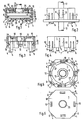
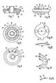
- Weitere vorteilhafte Ausgestaltungen der Erfindung sind nachfolgend anhand eines in der Zeichnung veranschaulichten Ausführungsbeispiels beschrieben. Dabei zeigen:
- Fig. 1 einen erfindungsgemässen Drehschalter von der Seite im Schnitt,
- Fig. 2 denselben von der Seite und in eine gedruckte Schaltungsplatte eingesetzt,
- Fig. 3 das Gehäuseteil von der Seite im Schnitt,
- Fig. 4 das Gehäuseteil von der Seite,
- Fig. 5 das Gehäuseteil von unten,
- Fig. 6 das Gehäuseteil von oben,
- Fig. 7 den Rotor von der Seite im Schnitt,
- Fig. 8 den Rotor von oben,
- Fig. 9 den Rotor von unten,
- Fig. 10 den Rotor von der Seite,
- Fig. 11 die Rastfeder von oben,
- Fig. 12 die Rastfeder von der Seite,
- Fig. 13 eine Kontaktfeder von oben und
- Fig. 14 die Kontaktfeder von der Seite.
- Mit 1 ist ein Gehäuseteil oder ein Gehäuse eines Drehschalters, insbesondere eines Miniatur-Stufendrehschalters, bezeichnet, das im Beispiel die Form einer offenen Dose aufweist. Zum Einsetzen und Fixieren desselben in einer gedruckten Schaltungsplatte 2 besitzt es auf der dieser zugewandten offenen Seite 3 nach unten abstehende, als Laschen 4 mit Rastnasen 5 ausgebildete Fortsätze. Diese sind in entsprechende Durchbrüche der gedruckten Schaltungsplatte 2 einsetzbar, wobei die an den überstehenden Enden 6 angeformten Rastnasen 5 die gedruckte Schaltungsplatte 2 hintergreifen.
- Zur genauen Lagefixierung des Gehäuseteils 1 auf der gedruckten Schaltungsplatte 2 sind gegebenenfalls zusätzlich ein oder mehrere Zentrierzapfen 7 am Gehäuseteil 1 angeformt, die in Zentrieröffnungen der gedruckten Schaltungsplatte 2 eingreifen können.
- Im Gehäuseteil 1 ist ein Rotor 8 dadurch drehbar gelagert, dass er von der offenen Seite 3 her gegen einen als Begrenzer der Einsetztiefe wirkenden Anschlag 9 eingesetzt und mittels als Rastelemente 10 wirkender federnder Rasthaken in der eingesetzten Lage drehbar gehaltert ist. Dies geschieht z.B. dadurch, dass der Abstand der Ebenen zwischen dem Anschlag und der Auflagefläche 11 der Rasthaken 10 um ein geringes Mass grösser ist als die Dicke des Rotors 8.
- Den Anschlag 9 bildet die Stirnfläche einer Lagerbuchse 12 des Gehäuseteils 1, in deren Öffnung 33 ein als Lagerzapfen 13 ausgebildeter zentrischer Schaft des Rotors 8 drehbar gelagert ist. Eine zusätzliche zweite axiale drehbare Lagerung kann die Mantelfläche 14 des Rotors 8 mit der Innenseite 15 des Gehäuseteils 1 bilden.
- Der Rotor 8 und der Lagerzapfen 13 sind mit einer durchgehenden Bohrung 16 versehen, in die eine Schaltwelle 17 mit Presssitz eingesetzt werden kann. Die Schaltwelle 17 kann so eingepresst werden, dass sie auf der offenen Seite 3 oder der dieser abgewandten geschlossenen und mit der Lagerbohrung der Lagerbuchse 12 versehenen Seite 18 des Gehäuseteils 1 oder auf beiden Seiten 3, 18 herausragt, so dass die Schaltwelle 17 wahlweise von einer der Seiten aus betätigbar ist. Es bleibt dann dem Anwender überlassen, wie er die gedruckte Schaltungsplatte in ein Gerät einbaut, da er in jedem Fall die Schaltwelle 17 so anbringen kann, dass sie von der gewünschten Seite aus betätigbar ist. Die Schaltwelle 17 kann auch beim Hersteller eingepresst oder in der gewünschten Lage eingespritzt bzw. bei der Herstellung des Rotors 8 mit eingeformt sein.
- Die innere Fläche 19 des Rotors 8 ist mit einem aus Erhöhungen 20 und/oder Vertiefungen 21 bestehenden Rastkranz 22 versehen. Die Erhöhungen 20 und/oder Vertiefungen 21 sind im Rastmass der Schaltschritte des Drehschalters vorgesehen. Zwischen denselben und der Innenwand 23 der geschlossenen Seite 18 des Gehäuseteils 1 ist eine vorzugsweise als Ringscheibe ausgebildete Rastfeder 24 vorgesehen. Letztere besitzt wenigstens eine Rastprägung 25, z.B. einen Kugeleindruck, der in eine Vertiefung 21 rastend einfedern kann. Hierdurch kann der Rotor 8 und die Schaltwelle 17 in den einzelnen Schaltstufen einrasten.
- Die Rastfeder 24 besitzt wenigstens eine Feder 26 oder eine Nut, die mit einer Nut 27 bzw. einer Feder des Gehäuseteils 1 eine Drehsicherung für die Rastfeder 24 bildet.
- Zweckmässig sind zwei sich diametral oder etwa diametral, z.B. je nachdem, ob eine gerade oder ungerade Anzahl von Schaltstufen vorgesehen ist, gegenüberliegende Rastprägungen 25 vorgesehen und die Feder 26 bzw. Nut ist bzw. sind dazu um ca. 90° versetzt.
- Auf der der gedruckten Schaltungsplatte 2 zugewandten Seite 28 des Rotors 8 sind mehrere Zapfen 29 angeformt. Auf diese ist eine mit Kontaktzungen 30 versehene Kontaktfeder 31 mittels Bohrungen 32 aufgesteckt. Durch Verformung, z.B. durch thermoplastische Verformung, wenn der Rotor 8 aus einem termoplastischen Material besteht, wird die Kontaktfeder 31 in ihrer Lage fixiert.
- Die Kontaktzungen 30 kommen beim Einsetzen in die gedruckte Schaltungsplatte 2 mit den als Fixkontakte ausgebildeten Leiterzügen der gedruckten Schaltungsplatte 2 in Kontakt und je nach Anordnung und Anzahl von Kontaktzungen 30 und Fixierkontakten sind unterschiedliche Schaltmöglichkeiten gegeben.
- Zweckmässig besteht das Gehäuseteil 1 aus einem federnden Material, insbesondere aus Kunststoff. Dadurch können die Laschen 4 und die Rastelemente 10 mit diesem ein einziges Bauteil bilden und beispielsweise aus einem geeigneten Kunststoff im Spritzverfahren hergestellt werden. Vorteilhaft sind dabei jeweils zwei oder mehrere Laschen 4 und Rastelemente 10 wechselweise vorgesehen, so dass das Gehäuseteil mit diesem mit einer einfachen zweiteiligen Spritzform hergestellt werden kann.
- Der erfindungsgemässe Drehschalter besitzt daher einen kompakten, aus wenigen Teilen bestehenden Aufbau und kann nach dem Einsetzen in eine gedruckte Schaltungsplatte oder eine andere geeignete Platine von einer der beiden Seiten aus oder von beiden Seiten aus senkrecht zur Richtung der Schaltungsplatte bzw. der Platine betätigt werden.
Claims (8)
Applications Claiming Priority (2)
| Application Number | Priority Date | Filing Date | Title |
|---|---|---|---|
| DE3225694 | 1982-07-09 | ||
| DE3225694A DE3225694C2 (de) | 1982-07-09 | 1982-07-09 | Drehschalteraufsatz |
Publications (2)
| Publication Number | Publication Date |
|---|---|
| EP0098532A1 EP0098532A1 (de) | 1984-01-18 |
| EP0098532B1 true EP0098532B1 (de) | 1986-04-23 |
Family
ID=6168020
Family Applications (1)
| Application Number | Title | Priority Date | Filing Date |
|---|---|---|---|
| EP83106377A Expired EP0098532B1 (de) | 1982-07-09 | 1983-06-30 | Drehschalter zur Befestigung auf einer gedruckten Schaltungsplatte |
Country Status (3)
| Country | Link |
|---|---|
| US (1) | US4551587A (de) |
| EP (1) | EP0098532B1 (de) |
| DE (1) | DE3225694C2 (de) |
Cited By (2)
| Publication number | Priority date | Publication date | Assignee | Title |
|---|---|---|---|---|
| DE19543980A1 (de) * | 1995-11-25 | 1997-05-28 | Hartmann Fritz Geraetebau | Codierschalter zur Bestückung einer Basisplatine |
| DE19801445A1 (de) * | 1998-01-16 | 1999-07-22 | Bosch Siemens Hausgeraete | Staubsauger |
Families Citing this family (22)
| Publication number | Priority date | Publication date | Assignee | Title |
|---|---|---|---|---|
| JPS59201637A (ja) * | 1983-04-28 | 1984-11-15 | キヤノン株式会社 | 電源装置 |
| DE3420496A1 (de) * | 1984-06-01 | 1985-12-05 | Karl-Heinz 2000 Hamburg Weymar | Adventskranz |
| DE3538546A1 (de) * | 1985-10-30 | 1987-05-07 | Braun Ag | Elektrischer drehschalter |
| DE3542086A1 (de) * | 1985-11-28 | 1987-06-04 | Berker Geb | Schalteraufbau fuer einen schalter, insbesondere geraeteeinbauschalter |
| DE3631722A1 (de) * | 1986-09-18 | 1988-03-31 | Standard Elektrik Lorenz Ag | Codier-drehschalter |
| EP0265732B1 (de) * | 1986-10-08 | 1994-01-26 | Omron Tateisi Electronics Co. | Elektronisches Bauelement mit Drehschalterrastfeder |
| DE8804603U1 (de) * | 1988-04-07 | 1988-05-19 | Robert Seuffer GmbH & Co, 7260 Calw | Einstelleinrichtung mit mehreren an einer Montageplatte angeordneten Kodierschaltern |
| US4861951A (en) * | 1988-07-13 | 1989-08-29 | Honeywell Inc. | Rotary switch with indexing structure mounted to a printed circuit board |
| US5010214A (en) * | 1988-08-11 | 1991-04-23 | Atsuo Yamazaki | Rotary switch |
| US4876416A (en) * | 1989-02-03 | 1989-10-24 | Actron Manufacturing Company | Multiple position rotary switch |
| US5086200A (en) * | 1990-06-04 | 1992-02-04 | Motorola, Inc. | Molded printed circuit for rotary switches |
| US5250770A (en) * | 1991-05-08 | 1993-10-05 | Indak Manufacturing Corp. | Rotary vacuum-electric switch |
| DE9307432U1 (de) * | 1993-05-17 | 1993-09-30 | Leonhardy Gmbh, 91244 Reichenschwand | Schlüsselschalter |
| JPH08167348A (ja) * | 1994-12-14 | 1996-06-25 | Matsushita Electric Ind Co Ltd | 回転操作型電子部品 |
| JPH08329777A (ja) * | 1995-05-30 | 1996-12-13 | Matsushita Electric Ind Co Ltd | ロータリースイッチ |
| DE19720196C2 (de) * | 1997-05-14 | 2000-03-23 | Trw Automotive Electron & Comp | Messwerk |
| CA2494641A1 (en) * | 2002-08-29 | 2004-03-11 | Emrise Corporation | Rotary switch detent structure independent of knob |
| WO2004044938A1 (en) * | 2002-11-05 | 2004-05-27 | Emrise Corporation | Low profile rotary switch with detent in the bushing |
| US7109430B2 (en) * | 2002-11-05 | 2006-09-19 | Emrise Corporation | Low profile rotary switch with detent in the bushing |
| US7067744B2 (en) * | 2004-04-16 | 2006-06-27 | Visteon Global Technologies, Inc. | Knob assembly |
| US7091437B2 (en) * | 2004-10-06 | 2006-08-15 | Premier Image Technology Corporation | Rotary switch |
| DE102014226618A1 (de) * | 2014-12-19 | 2016-06-23 | Siemens Aktiengesellschaft | Drehbetätiger |
Family Cites Families (13)
| Publication number | Priority date | Publication date | Assignee | Title |
|---|---|---|---|---|
| NL82989C (de) * | 1951-12-22 | |||
| US2896033A (en) * | 1955-01-27 | 1959-07-21 | Daystrom Inc | Printed circuit assembly |
| DE1158148B (de) * | 1961-10-12 | 1963-11-28 | Eduard Winkler Appbau G M B H | U-foermige Kontaktbruecke fuer Drehschalter, insbesondere Stufenschalter |
| DE1904082U (de) * | 1964-08-28 | 1964-11-12 | Continental Elektro Ind Ag | Drehschalter fuer gedruckte leiterplatten. |
| GB1185942A (en) * | 1968-05-10 | 1970-03-25 | Electronic Components Ltd | Improvements in or relating to Rotary Electrical Switches |
| DE2362141A1 (de) * | 1973-12-14 | 1975-11-06 | Standard Elektrik Lorenz Ag | Drehschalter fuer gedruckte schaltungen |
| US4034178A (en) * | 1975-10-09 | 1977-07-05 | Amp Incorporated | Rotary switch housing having integral flexible detenting walls and rotor mounting structure |
| US4107499A (en) * | 1976-12-22 | 1978-08-15 | Amp Incorporated | Switch assembly for circuit boards |
| DE7707490U1 (de) * | 1977-03-11 | 1977-07-07 | Licentia Patent-Verwaltungs-Gmbh, 6000 Frankfurt | Nockenschalter |
| DE2831204C2 (de) * | 1978-07-15 | 1980-05-29 | Standard Elektrik Lorenz Ag, 7000 Stuttgart | Miniatur-Stufenschalter |
| US4206334A (en) * | 1978-09-21 | 1980-06-03 | Illinois Tool Works Inc. | Rotatable electrical contact component with detent |
| US4246453A (en) * | 1979-07-12 | 1981-01-20 | Electro Audio Dynamics, Inc. | Switch |
| US4316067A (en) * | 1980-03-31 | 1982-02-16 | Amp Incorporated | Slide switch |
-
1982
- 1982-07-09 DE DE3225694A patent/DE3225694C2/de not_active Expired
-
1983
- 1983-06-23 US US06/507,039 patent/US4551587A/en not_active Expired - Fee Related
- 1983-06-30 EP EP83106377A patent/EP0098532B1/de not_active Expired
Cited By (2)
| Publication number | Priority date | Publication date | Assignee | Title |
|---|---|---|---|---|
| DE19543980A1 (de) * | 1995-11-25 | 1997-05-28 | Hartmann Fritz Geraetebau | Codierschalter zur Bestückung einer Basisplatine |
| DE19801445A1 (de) * | 1998-01-16 | 1999-07-22 | Bosch Siemens Hausgeraete | Staubsauger |
Also Published As
| Publication number | Publication date |
|---|---|
| US4551587A (en) | 1985-11-05 |
| DE3225694A1 (de) | 1984-01-12 |
| EP0098532A1 (de) | 1984-01-18 |
| DE3225694C2 (de) | 1985-02-07 |
Similar Documents
| Publication | Publication Date | Title |
|---|---|---|
| EP0098532B1 (de) | Drehschalter zur Befestigung auf einer gedruckten Schaltungsplatte | |
| DE69625128T2 (de) | Elektronischer Bauelement betätigt durch Drehbewegung, mit Druckschalter | |
| EP0278905B1 (de) | Kontakteinrichtung zur Übertragung von elektrischen Signalen zwischen Schloss und Schlüssel an einem Zylinderschloss | |
| DE2826721C2 (de) | ||
| DE60105892T2 (de) | Schwenkbare Verbindungsanordnung für eine herausklappbare Dachantenne | |
| DE10157215A1 (de) | Fahrzeuglampe und Drehantriebsvorrichtung | |
| DE19721514C2 (de) | Dreh-Tast-Schalter | |
| DE3425473C2 (de) | Mehrfachschalter mit drehbarem Schaltglied | |
| DE2806713C3 (de) | Elektrischer Schalter mit in Durchbrüchen angeordneten feststehenden Kontakten | |
| DE2523455C2 (de) | Elektrische Verbindungseinrichtung | |
| EP0180008B1 (de) | Sicherungselement | |
| DE60001480T2 (de) | Winkelkodierer | |
| DE2604466C3 (de) | Elektrischer Schalter mit in Buchsen einlegbaren, feststehenden Kontaktelementen | |
| EP0600153B1 (de) | Kontakthülse | |
| DE2824584C2 (de) | Mehrfach-Stufendrehschalter | |
| EP0093327B1 (de) | Elektrischer Drehschalter | |
| DE3107316A1 (de) | "schiebeschalter" | |
| DE3140772C2 (de) | Stufendrehschalter | |
| EP0337927B1 (de) | Bereichsumschalter, insbesondere für ein elektronisches Zeitrelais | |
| DE7733242U1 (de) | Stufendrehschalter | |
| DE2316549C3 (de) | Elektrischer Schalter | |
| DE2016992C3 (de) | Schaltvorrichtung mit geringem Rastmoment | |
| EP1423032B1 (de) | Küchengerät | |
| DE2502957A1 (de) | Stufen-drehschalter fuer vielfachmessinstrumente | |
| EP0132671A2 (de) | Impulsgeber |
Legal Events
| Date | Code | Title | Description |
|---|---|---|---|
| PUAI | Public reference made under article 153(3) epc to a published international application that has entered the european phase |
Free format text: ORIGINAL CODE: 0009012 |
|
| AK | Designated contracting states |
Designated state(s): CH FR GB LI |
|
| 17P | Request for examination filed |
Effective date: 19840310 |
|
| GRAA | (expected) grant |
Free format text: ORIGINAL CODE: 0009210 |
|
| AK | Designated contracting states |
Kind code of ref document: B1 Designated state(s): CH FR GB LI |
|
| ET | Fr: translation filed | ||
| PLBE | No opposition filed within time limit |
Free format text: ORIGINAL CODE: 0009261 |
|
| STAA | Information on the status of an ep patent application or granted ep patent |
Free format text: STATUS: NO OPPOSITION FILED WITHIN TIME LIMIT |
|
| 26N | No opposition filed | ||
| REG | Reference to a national code |
Ref country code: FR Ref legal event code: TP |
|
| REG | Reference to a national code |
Ref country code: GB Ref legal event code: 732 |
|
| PGFP | Annual fee paid to national office [announced via postgrant information from national office to epo] |
Ref country code: FR Payment date: 19890530 Year of fee payment: 7 |
|
| PGFP | Annual fee paid to national office [announced via postgrant information from national office to epo] |
Ref country code: GB Payment date: 19890531 Year of fee payment: 7 |
|
| PGFP | Annual fee paid to national office [announced via postgrant information from national office to epo] |
Ref country code: CH Payment date: 19890914 Year of fee payment: 7 |
|
| PG25 | Lapsed in a contracting state [announced via postgrant information from national office to epo] |
Ref country code: LI Effective date: 19900630 Ref country code: GB Effective date: 19900630 Ref country code: CH Effective date: 19900630 |
|
| GBPC | Gb: european patent ceased through non-payment of renewal fee | ||
| PG25 | Lapsed in a contracting state [announced via postgrant information from national office to epo] |
Ref country code: FR Effective date: 19910228 |
|
| REG | Reference to a national code |
Ref country code: CH Ref legal event code: PL |
|
| REG | Reference to a national code |
Ref country code: FR Ref legal event code: ST |