EP0098532B1 - Commutateur rotatif pour fixage à une plaque de circuit imprimé - Google Patents
Commutateur rotatif pour fixage à une plaque de circuit imprimé Download PDFInfo
- Publication number
- EP0098532B1 EP0098532B1 EP83106377A EP83106377A EP0098532B1 EP 0098532 B1 EP0098532 B1 EP 0098532B1 EP 83106377 A EP83106377 A EP 83106377A EP 83106377 A EP83106377 A EP 83106377A EP 0098532 B1 EP0098532 B1 EP 0098532B1
- Authority
- EP
- European Patent Office
- Prior art keywords
- circuit board
- printed circuit
- rotor
- rotary switch
- housing part
- Prior art date
- Legal status (The legal status is an assumption and is not a legal conclusion. Google has not performed a legal analysis and makes no representation as to the accuracy of the status listed.)
- Expired
Links
- 230000037431 insertion Effects 0.000 claims description 3
- 238000003780 insertion Methods 0.000 claims description 3
- 210000002105 tongue Anatomy 0.000 description 4
- 239000004033 plastic Substances 0.000 description 2
- 239000004020 conductor Substances 0.000 description 1
- 238000004049 embossing Methods 0.000 description 1
- 238000002347 injection Methods 0.000 description 1
- 239000007924 injection Substances 0.000 description 1
- 238000001746 injection moulding Methods 0.000 description 1
- 238000004519 manufacturing process Methods 0.000 description 1
- 239000012858 resilient material Substances 0.000 description 1
- 229920001169 thermoplastic Polymers 0.000 description 1
- 239000012815 thermoplastic material Substances 0.000 description 1
- 239000004416 thermosoftening plastic Substances 0.000 description 1
Images
Classifications
-
- H—ELECTRICITY
- H01—ELECTRIC ELEMENTS
- H01H—ELECTRIC SWITCHES; RELAYS; SELECTORS; EMERGENCY PROTECTIVE DEVICES
- H01H19/00—Switches operated by an operating part which is rotatable about a longitudinal axis thereof and which is acted upon directly by a solid body external to the switch, e.g. by a hand
- H01H19/54—Switches operated by an operating part which is rotatable about a longitudinal axis thereof and which is acted upon directly by a solid body external to the switch, e.g. by a hand the operating part having at least five or an unspecified number of operative positions
- H01H19/56—Angularly-movable actuating part carrying contacts, e.g. drum switch
- H01H19/58—Angularly-movable actuating part carrying contacts, e.g. drum switch having only axial contact pressure, e.g. disc switch, wafer switch
- H01H19/585—Angularly-movable actuating part carrying contacts, e.g. drum switch having only axial contact pressure, e.g. disc switch, wafer switch provided with printed circuit contacts
-
- H—ELECTRICITY
- H01—ELECTRIC ELEMENTS
- H01H—ELECTRIC SWITCHES; RELAYS; SELECTORS; EMERGENCY PROTECTIVE DEVICES
- H01H19/00—Switches operated by an operating part which is rotatable about a longitudinal axis thereof and which is acted upon directly by a solid body external to the switch, e.g. by a hand
- H01H19/02—Details
- H01H19/04—Cases; Covers
Definitions
- the invention relates to a rotary switch according to the first part of claim 1.
- Such a rotary switch is known from DE-U-1 904 082.
- the rotor is loosely inserted into the cup-like housing part and the contact pressure is generated via the detent spring of the detent mechanism.
- the rotor is practically axially floating.
- the rotor is axially loaded in each switching step due to the increased pressure of the locking cams on the locking spring. This pressure increase always causes a higher load on the contact springs and thus an increase in the contact pressure.
- the axial position of the rotor will change each time. As a result, there is increased wear on the contacts and contact tracks, with a corresponding reduction in the service life of the rotary switch.
- the rotor also has a bore with a slot for rotating the rotor using a suitable tool. Instead of the slot, a pin for a rotary knob can be formed on one side.
- the rotor has a shaft with a bore for the rotary shaft, which engages in a bearing bush of the housing part.
- a rotary shaft is inserted into the bore of the shaft, which is rotatably mounted on the one hand in the housing part and on the other hand in the printed circuit board.
- the axial play of the selector shaft itself is achieved by an end collar of the selector shaft on the side of the printed circuit board and a puncture with an inserted circlip on the opposite side of the selector shaft.
- a rotary switch is known from DE-A-2 362 141, in which the extensions are designed as contact pins, inserted into the printed circuit board and soldered to the cable runs.
- the rotor stands vertically on the printed circuit board and has a through opening for the switch shaft. The latter is therefore arranged parallel to the printed circuit board. The continuous opening is provided because several such rotary switches are to be assembled into a switch package.
- the present invention addresses the problem of mounting a rotary switch of the type mentioned in the introduction on a printed circuit board arranged parallel to a front plate of a device housing etc. and e.g. to be able to operate from the front panel.
- This object is achieved by the features specified in the characterizing part of claim 1.
- a definite, at least axially practically play-free position fixing of the rotor can be achieved.
- the rotary switch can always be operated from the outside, regardless of whether the printed circuit board is facing the component side or the side facing away from the operating side of the device.
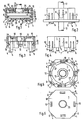
- a printed circuit board 2 it has on the open side 3 facing this, protruding downwards, designed as tabs 4 with locking lugs 5. These can be inserted into corresponding openings in the printed circuit board 2, the locking lugs 5 formed on the projecting ends 6 engaging behind the printed circuit board 2.
- one or more centering pins 7 are optionally formed on the housing part 1, which can engage in centering openings of the printed circuit board 2.
- a rotor 8 is rotatably supported in the housing part 1 in that it is inserted from the open side 3 against a stop 9 acting as a limiter of the insertion depth and is rotatably supported in the inserted position by means of resilient latching hooks acting as latching elements 10. This happens e.g. in that the distance between the planes between the stop and the support surface 11 of the latching hooks 10 is slightly larger than the thickness of the rotor 8.
- the stop 9 forms the end face of a bearing bush 12 of the housing part 1, in the opening 33 of which a central shaft of the rotor 8 designed as a bearing journal 13 is rotatably mounted.
- An additional second axially rotatable mounting can form the outer surface 14 of the rotor 8 with the inside 15 of the housing part 1.
- the rotor 8 and the bearing journal 13 are provided with a through bore 16 into which a selector shaft 17 with a press fit can be inserted.
- the selector shaft 17 can be pressed in so that it protrudes on the open side 3 or the closed side 18 facing away from it and provided with the bearing bore of the bearing bush 12 on the side 18 of the housing part 1 or on both sides 3, 18, so that the selector shaft 17 is optionally from one the sides can be operated. It is then up to the user how to install the printed circuit board in a device, since he is in any case can mount the control shaft 17 so that it can be actuated from the desired side.
- the selector shaft 17 can also be pressed in at the manufacturer or injected in the desired position or molded in during the manufacture of the rotor 8.
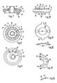
- the inner surface 19 of the rotor 8 is provided with a locking ring 22 consisting of elevations 20 and / or depressions 21.
- the elevations 20 and / or depressions 21 are provided in the locking dimension of the switching steps of the rotary switch.
- a detent spring 24, preferably in the form of an annular disk, is provided between the same and the inner wall 23 of the closed side 18 of the housing part 1.
- the latter has at least one catch embossing 25, e.g. a ball impression, which can spring into a recess 21. This allows the rotor 8 and the selector shaft 17 to engage in the individual switching stages.
- the detent spring 24 has at least one spring 26 or a groove, which forms a rotation lock for the detent spring 24 with a groove 27 or a spring of the housing part 1.
- Two are expediently diametrically or approximately diametrically, e.g. Depending on whether an even or odd number of switching stages is provided, opposing catch embossments 25 are provided and the tongue 26 or groove is or are offset by approximately 90 °.
- a plurality of pins 29 are formed on the side 28 of the rotor 8 facing the printed circuit board 2, a plurality of pins 29 are formed.
- a contact spring 31 provided with contact tongues 30 is plugged onto these by means of bores 32.
- the contact spring 31 is fixed in its position by thermoplastic deformation, if the rotor 8 consists of a thermoplastic material.
- the contact tongues 30 When inserted into the printed circuit board 2, the contact tongues 30 come into contact with the conductor tracks of the printed circuit board 2 designed as fixed contacts and, depending on the arrangement and number of contact tongues 30 and fixing contacts, there are different switching options.
- the housing part 1 expediently consists of a resilient material, in particular of plastic.
- the tabs 4 and the latching elements 10 can form a single component with the latter and can be produced, for example, from a suitable plastic by injection molding.
- two or more tabs 4 and latching elements 10 are provided alternately, so that the housing part can be produced with this using a simple two-part injection mold.
- the rotary switch according to the invention therefore has a compact structure consisting of a few parts and can be actuated from one of the two sides or from both sides perpendicular to the direction of the circuit board or the board after insertion into a printed circuit board or another suitable board.
Landscapes
- Rotary Switch, Piano Key Switch, And Lever Switch (AREA)
- Switch Cases, Indication, And Locking (AREA)
Claims (8)
Applications Claiming Priority (2)
| Application Number | Priority Date | Filing Date | Title |
|---|---|---|---|
| DE3225694 | 1982-07-09 | ||
| DE3225694A DE3225694C2 (de) | 1982-07-09 | 1982-07-09 | Drehschalteraufsatz |
Publications (2)
| Publication Number | Publication Date |
|---|---|
| EP0098532A1 EP0098532A1 (fr) | 1984-01-18 |
| EP0098532B1 true EP0098532B1 (fr) | 1986-04-23 |
Family
ID=6168020
Family Applications (1)
| Application Number | Title | Priority Date | Filing Date |
|---|---|---|---|
| EP83106377A Expired EP0098532B1 (fr) | 1982-07-09 | 1983-06-30 | Commutateur rotatif pour fixage à une plaque de circuit imprimé |
Country Status (3)
| Country | Link |
|---|---|
| US (1) | US4551587A (fr) |
| EP (1) | EP0098532B1 (fr) |
| DE (1) | DE3225694C2 (fr) |
Cited By (2)
| Publication number | Priority date | Publication date | Assignee | Title |
|---|---|---|---|---|
| DE19543980A1 (de) * | 1995-11-25 | 1997-05-28 | Hartmann Fritz Geraetebau | Codierschalter zur Bestückung einer Basisplatine |
| DE19801445A1 (de) * | 1998-01-16 | 1999-07-22 | Bosch Siemens Hausgeraete | Staubsauger |
Families Citing this family (22)
| Publication number | Priority date | Publication date | Assignee | Title |
|---|---|---|---|---|
| JPS59201637A (ja) * | 1983-04-28 | 1984-11-15 | キヤノン株式会社 | 電源装置 |
| DE3420496A1 (de) * | 1984-06-01 | 1985-12-05 | Karl-Heinz 2000 Hamburg Weymar | Adventskranz |
| DE3538546A1 (de) * | 1985-10-30 | 1987-05-07 | Braun Ag | Elektrischer drehschalter |
| DE3542086A1 (de) * | 1985-11-28 | 1987-06-04 | Berker Geb | Schalteraufbau fuer einen schalter, insbesondere geraeteeinbauschalter |
| DE3631722A1 (de) * | 1986-09-18 | 1988-03-31 | Standard Elektrik Lorenz Ag | Codier-drehschalter |
| EP0265732B1 (fr) * | 1986-10-08 | 1994-01-26 | Omron Tateisi Electronics Co. | Composant électronique ayant un ressort à cran d'arrêt d'un commutateur rotatif |
| DE8804603U1 (de) * | 1988-04-07 | 1988-05-19 | Robert Seuffer GmbH & Co, 7260 Calw | Einstelleinrichtung mit mehreren an einer Montageplatte angeordneten Kodierschaltern |
| US4861951A (en) * | 1988-07-13 | 1989-08-29 | Honeywell Inc. | Rotary switch with indexing structure mounted to a printed circuit board |
| US5010214A (en) * | 1988-08-11 | 1991-04-23 | Atsuo Yamazaki | Rotary switch |
| US4876416A (en) * | 1989-02-03 | 1989-10-24 | Actron Manufacturing Company | Multiple position rotary switch |
| US5086200A (en) * | 1990-06-04 | 1992-02-04 | Motorola, Inc. | Molded printed circuit for rotary switches |
| US5250770A (en) * | 1991-05-08 | 1993-10-05 | Indak Manufacturing Corp. | Rotary vacuum-electric switch |
| DE9307432U1 (de) * | 1993-05-17 | 1993-09-30 | Leonhardy Gmbh, 91244 Reichenschwand | Schlüsselschalter |
| JPH08167348A (ja) * | 1994-12-14 | 1996-06-25 | Matsushita Electric Ind Co Ltd | 回転操作型電子部品 |
| JPH08329777A (ja) * | 1995-05-30 | 1996-12-13 | Matsushita Electric Ind Co Ltd | ロータリースイッチ |
| DE19720196C2 (de) * | 1997-05-14 | 2000-03-23 | Trw Automotive Electron & Comp | Messwerk |
| CA2494641A1 (fr) * | 2002-08-29 | 2004-03-11 | Emrise Corporation | Structure crantee de commutateur rotatif independante de la poignee |
| WO2004044938A1 (fr) * | 2002-11-05 | 2004-05-27 | Emrise Corporation | Commutateur rotatif de dimensions compactes avec dispositif d'encliquetage contenu dans la traversee |
| US7109430B2 (en) * | 2002-11-05 | 2006-09-19 | Emrise Corporation | Low profile rotary switch with detent in the bushing |
| US7067744B2 (en) * | 2004-04-16 | 2006-06-27 | Visteon Global Technologies, Inc. | Knob assembly |
| US7091437B2 (en) * | 2004-10-06 | 2006-08-15 | Premier Image Technology Corporation | Rotary switch |
| DE102014226618A1 (de) * | 2014-12-19 | 2016-06-23 | Siemens Aktiengesellschaft | Drehbetätiger |
Family Cites Families (13)
| Publication number | Priority date | Publication date | Assignee | Title |
|---|---|---|---|---|
| NL82989C (fr) * | 1951-12-22 | |||
| US2896033A (en) * | 1955-01-27 | 1959-07-21 | Daystrom Inc | Printed circuit assembly |
| DE1158148B (de) * | 1961-10-12 | 1963-11-28 | Eduard Winkler Appbau G M B H | U-foermige Kontaktbruecke fuer Drehschalter, insbesondere Stufenschalter |
| DE1904082U (de) * | 1964-08-28 | 1964-11-12 | Continental Elektro Ind Ag | Drehschalter fuer gedruckte leiterplatten. |
| GB1185942A (en) * | 1968-05-10 | 1970-03-25 | Electronic Components Ltd | Improvements in or relating to Rotary Electrical Switches |
| DE2362141A1 (de) * | 1973-12-14 | 1975-11-06 | Standard Elektrik Lorenz Ag | Drehschalter fuer gedruckte schaltungen |
| US4034178A (en) * | 1975-10-09 | 1977-07-05 | Amp Incorporated | Rotary switch housing having integral flexible detenting walls and rotor mounting structure |
| US4107499A (en) * | 1976-12-22 | 1978-08-15 | Amp Incorporated | Switch assembly for circuit boards |
| DE7707490U1 (de) * | 1977-03-11 | 1977-07-07 | Licentia Patent-Verwaltungs-Gmbh, 6000 Frankfurt | Nockenschalter |
| DE2831204C2 (de) * | 1978-07-15 | 1980-05-29 | Standard Elektrik Lorenz Ag, 7000 Stuttgart | Miniatur-Stufenschalter |
| US4206334A (en) * | 1978-09-21 | 1980-06-03 | Illinois Tool Works Inc. | Rotatable electrical contact component with detent |
| US4246453A (en) * | 1979-07-12 | 1981-01-20 | Electro Audio Dynamics, Inc. | Switch |
| US4316067A (en) * | 1980-03-31 | 1982-02-16 | Amp Incorporated | Slide switch |
-
1982
- 1982-07-09 DE DE3225694A patent/DE3225694C2/de not_active Expired
-
1983
- 1983-06-23 US US06/507,039 patent/US4551587A/en not_active Expired - Fee Related
- 1983-06-30 EP EP83106377A patent/EP0098532B1/fr not_active Expired
Cited By (2)
| Publication number | Priority date | Publication date | Assignee | Title |
|---|---|---|---|---|
| DE19543980A1 (de) * | 1995-11-25 | 1997-05-28 | Hartmann Fritz Geraetebau | Codierschalter zur Bestückung einer Basisplatine |
| DE19801445A1 (de) * | 1998-01-16 | 1999-07-22 | Bosch Siemens Hausgeraete | Staubsauger |
Also Published As
| Publication number | Publication date |
|---|---|
| US4551587A (en) | 1985-11-05 |
| DE3225694A1 (de) | 1984-01-12 |
| EP0098532A1 (fr) | 1984-01-18 |
| DE3225694C2 (de) | 1985-02-07 |
Similar Documents
| Publication | Publication Date | Title |
|---|---|---|
| EP0098532B1 (fr) | Commutateur rotatif pour fixage à une plaque de circuit imprimé | |
| DE69625128T2 (de) | Elektronischer Bauelement betätigt durch Drehbewegung, mit Druckschalter | |
| EP0278905B1 (fr) | Dispositif à contact pour la transmission de signaux électriques entre serrure et clé, application à une serrure à barillet | |
| DE2826721C2 (fr) | ||
| DE60105892T2 (de) | Schwenkbare Verbindungsanordnung für eine herausklappbare Dachantenne | |
| DE10157215A1 (de) | Fahrzeuglampe und Drehantriebsvorrichtung | |
| DE19721514C2 (de) | Dreh-Tast-Schalter | |
| DE3425473C2 (de) | Mehrfachschalter mit drehbarem Schaltglied | |
| DE2806713C3 (de) | Elektrischer Schalter mit in Durchbrüchen angeordneten feststehenden Kontakten | |
| DE2523455C2 (de) | Elektrische Verbindungseinrichtung | |
| EP0180008B1 (fr) | Elément fusible | |
| DE60001480T2 (de) | Winkelkodierer | |
| DE2604466C3 (de) | Elektrischer Schalter mit in Buchsen einlegbaren, feststehenden Kontaktelementen | |
| EP0600153B1 (fr) | Douille de contact | |
| DE2824584C2 (de) | Mehrfach-Stufendrehschalter | |
| EP0093327B1 (fr) | Interrupteur électrique rotatif | |
| DE3107316A1 (de) | "schiebeschalter" | |
| DE3140772C2 (de) | Stufendrehschalter | |
| EP0337927B1 (fr) | Commutateur de gamme, en particulier pour un relais temporisé | |
| DE7733242U1 (de) | Stufendrehschalter | |
| DE2316549C3 (de) | Elektrischer Schalter | |
| DE2016992C3 (de) | Schaltvorrichtung mit geringem Rastmoment | |
| EP1423032B1 (fr) | Appareil de cuisine | |
| DE2502957A1 (de) | Stufen-drehschalter fuer vielfachmessinstrumente | |
| EP0132671A2 (fr) | Générateur d'impulsions |
Legal Events
| Date | Code | Title | Description |
|---|---|---|---|
| PUAI | Public reference made under article 153(3) epc to a published international application that has entered the european phase |
Free format text: ORIGINAL CODE: 0009012 |
|
| AK | Designated contracting states |
Designated state(s): CH FR GB LI |
|
| 17P | Request for examination filed |
Effective date: 19840310 |
|
| GRAA | (expected) grant |
Free format text: ORIGINAL CODE: 0009210 |
|
| AK | Designated contracting states |
Kind code of ref document: B1 Designated state(s): CH FR GB LI |
|
| ET | Fr: translation filed | ||
| PLBE | No opposition filed within time limit |
Free format text: ORIGINAL CODE: 0009261 |
|
| STAA | Information on the status of an ep patent application or granted ep patent |
Free format text: STATUS: NO OPPOSITION FILED WITHIN TIME LIMIT |
|
| 26N | No opposition filed | ||
| REG | Reference to a national code |
Ref country code: FR Ref legal event code: TP |
|
| REG | Reference to a national code |
Ref country code: GB Ref legal event code: 732 |
|
| PGFP | Annual fee paid to national office [announced via postgrant information from national office to epo] |
Ref country code: FR Payment date: 19890530 Year of fee payment: 7 |
|
| PGFP | Annual fee paid to national office [announced via postgrant information from national office to epo] |
Ref country code: GB Payment date: 19890531 Year of fee payment: 7 |
|
| PGFP | Annual fee paid to national office [announced via postgrant information from national office to epo] |
Ref country code: CH Payment date: 19890914 Year of fee payment: 7 |
|
| PG25 | Lapsed in a contracting state [announced via postgrant information from national office to epo] |
Ref country code: LI Effective date: 19900630 Ref country code: GB Effective date: 19900630 Ref country code: CH Effective date: 19900630 |
|
| GBPC | Gb: european patent ceased through non-payment of renewal fee | ||
| PG25 | Lapsed in a contracting state [announced via postgrant information from national office to epo] |
Ref country code: FR Effective date: 19910228 |
|
| REG | Reference to a national code |
Ref country code: CH Ref legal event code: PL |
|
| REG | Reference to a national code |
Ref country code: FR Ref legal event code: ST |