EP0099032B1 - Culasse pour un moteur à combustion interne à multi-cylindres et avec refroidissement par eau - Google Patents
Culasse pour un moteur à combustion interne à multi-cylindres et avec refroidissement par eau Download PDFInfo
- Publication number
- EP0099032B1 EP0099032B1 EP83106427A EP83106427A EP0099032B1 EP 0099032 B1 EP0099032 B1 EP 0099032B1 EP 83106427 A EP83106427 A EP 83106427A EP 83106427 A EP83106427 A EP 83106427A EP 0099032 B1 EP0099032 B1 EP 0099032B1
- Authority
- EP
- European Patent Office
- Prior art keywords
- duct
- combustion chambers
- cylinder head
- row
- longitudinal
- Prior art date
- Legal status (The legal status is an assumption and is not a legal conclusion. Google has not performed a legal analysis and makes no representation as to the accuracy of the status listed.)
- Expired
Links
- 238000002485 combustion reaction Methods 0.000 title claims abstract description 23
- XLYOFNOQVPJJNP-UHFFFAOYSA-N water Substances O XLYOFNOQVPJJNP-UHFFFAOYSA-N 0.000 claims abstract description 20
- 238000001816 cooling Methods 0.000 claims description 7
- 238000004512 die casting Methods 0.000 claims 1
- 238000007599 discharging Methods 0.000 claims 1
- 238000000034 method Methods 0.000 claims 1
- 238000007789 sealing Methods 0.000 description 3
- 238000005266 casting Methods 0.000 description 2
- 238000005553 drilling Methods 0.000 description 2
- NDAUXUAQIAJITI-UHFFFAOYSA-N albuterol Chemical compound CC(C)(C)NCC(O)C1=CC=C(O)C(CO)=C1 NDAUXUAQIAJITI-UHFFFAOYSA-N 0.000 description 1
- 239000000498 cooling water Substances 0.000 description 1
- 238000010438 heat treatment Methods 0.000 description 1
- 238000004519 manufacturing process Methods 0.000 description 1
Images
Classifications
-
- F—MECHANICAL ENGINEERING; LIGHTING; HEATING; WEAPONS; BLASTING
- F02—COMBUSTION ENGINES; HOT-GAS OR COMBUSTION-PRODUCT ENGINE PLANTS
- F02F—CYLINDERS, PISTONS OR CASINGS, FOR COMBUSTION ENGINES; ARRANGEMENTS OF SEALINGS IN COMBUSTION ENGINES
- F02F1/00—Cylinders; Cylinder heads
- F02F1/24—Cylinder heads
- F02F1/26—Cylinder heads having cooling means
- F02F1/36—Cylinder heads having cooling means for liquid cooling
- F02F1/38—Cylinder heads having cooling means for liquid cooling the cylinder heads being of overhead valve type
-
- F—MECHANICAL ENGINEERING; LIGHTING; HEATING; WEAPONS; BLASTING
- F02—COMBUSTION ENGINES; HOT-GAS OR COMBUSTION-PRODUCT ENGINE PLANTS
- F02F—CYLINDERS, PISTONS OR CASINGS, FOR COMBUSTION ENGINES; ARRANGEMENTS OF SEALINGS IN COMBUSTION ENGINES
- F02F1/00—Cylinders; Cylinder heads
- F02F1/24—Cylinder heads
- F02F1/26—Cylinder heads having cooling means
- F02F1/36—Cylinder heads having cooling means for liquid cooling
- F02F1/40—Cylinder heads having cooling means for liquid cooling cylinder heads with means for directing, guiding, or distributing liquid stream
-
- F—MECHANICAL ENGINEERING; LIGHTING; HEATING; WEAPONS; BLASTING
- F02—COMBUSTION ENGINES; HOT-GAS OR COMBUSTION-PRODUCT ENGINE PLANTS
- F02F—CYLINDERS, PISTONS OR CASINGS, FOR COMBUSTION ENGINES; ARRANGEMENTS OF SEALINGS IN COMBUSTION ENGINES
- F02F1/00—Cylinders; Cylinder heads
- F02F1/24—Cylinder heads
- F02F2001/244—Arrangement of valve stems in cylinder heads
- F02F2001/245—Arrangement of valve stems in cylinder heads the valve stems being orientated at an angle with the cylinder axis
Definitions
- the invention relates to a cylinder head of the type according to the preamble of claim 1.
- the longitudinal channel extends next to the row of combustion chambers just above the parting plane of the cylinder head to the cylinder block.
- the connecting channels are parallel to this parting plane and at an angle to the row of combustion chambers and to the longitudinal channel. All connection channels are drilled from an outside of the cylinder head and closed there with sealing caps. This training is only suitable for parallel hanging Ventilan orders, because the parallel to the parting connection channels in a V-shaped valve arrangement do not allow targeted cooling of the hottest points of the cylinder head.
- the object of the invention is to arrange the longitudinal channel and the connecting channels so that a targeted cooling of hot cylinder head areas in all conventional cylinder head types and a design of the longitudinal channel and the connecting channels can be achieved directly by drilling or casting molds without additional sealing measures.
- This object is achieved by the features of the characterizing part of claim 1.
- This design results in a direct cooling effect of the longitudinal channel and the connecting channels at the hottest areas of the cylinder head. Since the straight-line connecting channels start directly from the niche-like water spaces, no plugs or sealing lids are required, so that simple and inexpensive production is possible.
- a further development of the invention for a cylinder head with V-shaped hanging and offset in the longitudinal extent of the same valve is characterized in claim 2.
- This design specifically cools places of the cylinder head which are subject to high thermal loads, in particular the area around the exhaust ports, the area between the exhaust port and spark plug and the combustion chamber walls by means of a targeted longitudinal and transverse flow through the longitudinal port and the connecting ports.
- the oil temperature in the cylinder head is kept low due to its good cooling.
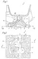
- a die-cast cylinder head 1 for water-cooled internal combustion engines has several niche-like water spaces 2 and 3.
- the water spaces 2 and 3 can be formed towards the parting plane 1 'between the cylinder head 1 and the cylinder block (not shown) and are arranged around combustion chambers 4.
- the water spaces 2 and 3 lie on the outside of the cylinder head 1. They have sections 5 and 6 which extend between two adjacent combustion chambers 4.
- a longitudinal channel 7 is arranged at a distance from the combustion chambers 4.
- Connecting channels 8, 9 and 10 extend from the water spaces 2 and 3 and from section 5 of the water space 2 to the longitudinal channel 7.
- the connecting channels 8, 9 and 10 are arranged obliquely to the parting plane 1 '. They are made by drilling from water spaces 2 and 3 or from section 5 of water space 2.
- connecting channels 8, 9 and 10 by casting mold trains.
- the longitudinal channel 7 can be shaped toward the end faces of the cylinder head 1, not shown. There is no need for plugs and other closures, since the connecting channels start directly from the water spaces 2 and 3 or from section 5 of the water space 2.
- the cylinder head 1 has laterally opening inlet and outlet channels 11 and 12, respectively.
- the valves of which only the valve guides 13 and 14 are shown, are suspended, offset and arranged in a V-shape with respect to one another.
- the inlet valve seat 15 and the outlet valve seat 16 are arranged correspondingly offset from one another.
- a bore 17 for a spark plug is arranged opposite the inlet valve seat 15, so that it is on the same side as the outlet channel 12.
- the connecting channels 8 and 10 are arranged on both sides of the exhaust valve seat 16 and the exhaust channel 12.
- the connecting channel 8 is thus between the outlet channel 12 and the bore 17 for the spark plug.
- the connecting channel 9 is arranged essentially opposite the outlet channel 12.
- the longitudinal channel 7 lies between the valve guides 13 and 14.
- the angle of inclination of the connecting channels 8, 9 and 10 with respect to the parting plane 1 ' is between 30 and 60 °.
- the design described results in a cylinder head 1 with a low operating weight, since it has only a small water content. Due to the low water content, a good flow and cooling of the cylinder head can also be ensured with a water pump of relatively low drive power will.
- the longitudinal channel 7 cools the valve guides 13 and 14 and, moreover, protects the oil located in the valve chamber 18 lying above from excessive heating.
- thermally highly stressed points, in particular the vicinity of the exhaust ducts 12, the area between the exhaust duct 12 and the bore 17 for the spark plug and the walls of the combustion chambers 4 are preferably cooled by means of a defined cross flow flowing through the connecting ducts 8, 9 and 10 .
Landscapes
- Engineering & Computer Science (AREA)
- Chemical & Material Sciences (AREA)
- Combustion & Propulsion (AREA)
- Mechanical Engineering (AREA)
- General Engineering & Computer Science (AREA)
- Cylinder Crankcases Of Internal Combustion Engines (AREA)
Claims (2)
culasse caractérisée en ce que :
Priority Applications (1)
| Application Number | Priority Date | Filing Date | Title |
|---|---|---|---|
| AT83106427T ATE12973T1 (de) | 1982-07-03 | 1983-07-01 | Zylinderkopf fuer fluessigkeitsgekuehlte mehrzylinder-brennkraftmaschinen. |
Applications Claiming Priority (2)
| Application Number | Priority Date | Filing Date | Title |
|---|---|---|---|
| DE3224945A DE3224945C1 (de) | 1982-07-03 | 1982-07-03 | Zylinderkopf fuer fluessigkeitsgekuehlte Mehrzylinder-Brennkraftmaschinen |
| DE3224945 | 1982-07-03 |
Publications (3)
| Publication Number | Publication Date |
|---|---|
| EP0099032A1 EP0099032A1 (fr) | 1984-01-25 |
| EP0099032B1 true EP0099032B1 (fr) | 1985-04-24 |
| EP0099032B2 EP0099032B2 (fr) | 1989-03-01 |
Family
ID=6167563
Family Applications (1)
| Application Number | Title | Priority Date | Filing Date |
|---|---|---|---|
| EP83106427A Expired EP0099032B2 (fr) | 1982-07-03 | 1983-07-01 | Culasse pour un moteur à combustion interne à multi-cylindres et avec refroidissement par eau |
Country Status (5)
| Country | Link |
|---|---|
| US (1) | US4471726A (fr) |
| EP (1) | EP0099032B2 (fr) |
| JP (1) | JPS5920548A (fr) |
| AT (1) | ATE12973T1 (fr) |
| DE (2) | DE3224945C1 (fr) |
Families Citing this family (12)
| Publication number | Priority date | Publication date | Assignee | Title |
|---|---|---|---|---|
| US4714058A (en) * | 1984-12-10 | 1987-12-22 | Mazda Motor Corporation | Spark-ignited internal combustion engine |
| JPS6213759A (ja) * | 1985-07-10 | 1987-01-22 | Toyota Motor Corp | 内燃機関のシリンダヘツドの冷却水通路構造 |
| DE3609762A1 (de) * | 1986-03-22 | 1987-09-24 | Kloeckner Humboldt Deutz Ag | Zylinderkopf fuer eine brennkraftmaschine |
| DE3639691A1 (de) * | 1986-11-20 | 1988-06-01 | Kloeckner Humboldt Deutz Ag | Dieselbrennkraftmaschine |
| DE4102358C2 (de) * | 1991-01-26 | 2000-05-11 | Volkswagen Ag | Im Druckgußverfahren herzustellendes Formteil, Verfahren zur Herstellung des Formteils sowie Hohlkörper zur Einlage in das Formteil |
| DE4342800C2 (de) * | 1993-12-15 | 1999-12-09 | Deutz Ag | Hubkolbenbrennkraftmaschine |
| DE19635535C2 (de) * | 1996-09-02 | 1998-07-23 | Daimler Benz Ag | Gegossener Zylinderkopf einer mehrzylindrigen Brennkraftmaschine |
| DE19637122C1 (de) * | 1996-09-12 | 1998-01-02 | Porsche Ag | Flüssigkeitsgekühlter Zylinderkopf |
| DE19806272C1 (de) * | 1998-02-16 | 1999-04-15 | Lipcan Sergiu Valentin | Im Druckgußverfahren herstellbarer Leichtmetallzylinderkopf für eine flüssigkeitsgekühlte Brennkraftmaschine mit drei Ventilen pro Zylinder |
| US20020124815A1 (en) * | 2001-03-06 | 2002-09-12 | Toyota Jidosha Kabushiki Kaisha | Cooling structure of cylinder head and method for manufacturing cylinder head |
| JP4432879B2 (ja) | 2005-11-11 | 2010-03-17 | トヨタ自動車株式会社 | 内燃機関のオイル通路構造 |
| AT505591B8 (de) * | 2008-10-02 | 2010-04-15 | Avl List Gmbh | Brennkraftmaschine mit einem zylinderkopf |
Citations (7)
| Publication number | Priority date | Publication date | Assignee | Title |
|---|---|---|---|---|
| US147140A (en) | 1874-02-03 | Improvement in propulsion of canal-boats | ||
| DE874847C (de) | 1944-06-25 | 1953-04-27 | Messerschmitt Boelkow Blohm | Zylinderkopfblock |
| DE886545C (de) | 1944-05-08 | 1953-08-13 | Sulzer Ag | Brennkraftmaschine |
| FR1272322A (fr) | 1960-10-27 | 1961-09-22 | Caterpillar Tractor Co | Culasse de moteur agencée pour le refroidissement des soupapes d'échappement |
| DE2756006A1 (de) | 1976-12-22 | 1978-07-06 | Ford Werke Ag | Kuehlsystem fuer den zylinderblock einer hubkolben-brennkraftmaschine von kraftfahrzeugen |
| DE2839199A1 (de) | 1978-09-08 | 1980-03-13 | Bayerische Motoren Werke Ag | Im druckgiessverfahren herstellbarer zylinderkopf fuer wassergekuehlte brennkraftmaschinen |
| DE3123538A1 (de) | 1980-06-16 | 1982-03-25 | List, Hans, Prof. Dipl.-Ing. Dr.Dr.h.c., Graz | Wassergekuehlte mehrzylinder-brennkraftmaschine |
Family Cites Families (7)
| Publication number | Priority date | Publication date | Assignee | Title |
|---|---|---|---|---|
| DE1801765A1 (de) * | 1968-10-08 | 1970-07-16 | Bayerische Motoren Werke Ag | Brennraum fuer eine mit Gemischverdichtung und Fremdzuendung arbeitende Viertakt-Brennkraftmaschine |
| FR1506513A (fr) * | 1966-11-08 | 1967-12-22 | Renault | Perfectionnements au tracé des culasses de moteurs à explosion |
| NL7103836A (fr) * | 1970-03-23 | 1971-09-27 | ||
| AT329323B (de) * | 1972-11-06 | 1976-05-10 | Denzel Kraftfahrzeug Wolfgang | Zylinderkopf fur brennkraftmaschinen |
| JPS51126409A (en) * | 1975-04-25 | 1976-11-04 | Nissan Motor Co Ltd | Cylinder head of automotive engine |
| US4147140A (en) * | 1976-06-22 | 1979-04-03 | National Research Development Corporation | Cylinder head cooling arrangement for internal combustion engines |
| DE3030200C2 (de) * | 1980-08-09 | 1984-11-22 | Bayerische Motoren Werke AG, 8000 München | Zylinderkopf für Brennkraftmaschinen |
-
1982
- 1982-07-03 DE DE3224945A patent/DE3224945C1/de not_active Expired
-
1983
- 1983-07-01 DE DE8383106427T patent/DE3360141D1/de not_active Expired
- 1983-07-01 US US06/510,218 patent/US4471726A/en not_active Expired - Fee Related
- 1983-07-01 EP EP83106427A patent/EP0099032B2/fr not_active Expired
- 1983-07-01 JP JP58118420A patent/JPS5920548A/ja active Granted
- 1983-07-01 AT AT83106427T patent/ATE12973T1/de active
Patent Citations (7)
| Publication number | Priority date | Publication date | Assignee | Title |
|---|---|---|---|---|
| US147140A (en) | 1874-02-03 | Improvement in propulsion of canal-boats | ||
| DE886545C (de) | 1944-05-08 | 1953-08-13 | Sulzer Ag | Brennkraftmaschine |
| DE874847C (de) | 1944-06-25 | 1953-04-27 | Messerschmitt Boelkow Blohm | Zylinderkopfblock |
| FR1272322A (fr) | 1960-10-27 | 1961-09-22 | Caterpillar Tractor Co | Culasse de moteur agencée pour le refroidissement des soupapes d'échappement |
| DE2756006A1 (de) | 1976-12-22 | 1978-07-06 | Ford Werke Ag | Kuehlsystem fuer den zylinderblock einer hubkolben-brennkraftmaschine von kraftfahrzeugen |
| DE2839199A1 (de) | 1978-09-08 | 1980-03-13 | Bayerische Motoren Werke Ag | Im druckgiessverfahren herstellbarer zylinderkopf fuer wassergekuehlte brennkraftmaschinen |
| DE3123538A1 (de) | 1980-06-16 | 1982-03-25 | List, Hans, Prof. Dipl.-Ing. Dr.Dr.h.c., Graz | Wassergekuehlte mehrzylinder-brennkraftmaschine |
Also Published As
| Publication number | Publication date |
|---|---|
| DE3360141D1 (en) | 1985-05-30 |
| JPS5920548A (ja) | 1984-02-02 |
| ATE12973T1 (de) | 1985-05-15 |
| EP0099032A1 (fr) | 1984-01-25 |
| US4471726A (en) | 1984-09-18 |
| DE3224945C1 (de) | 1984-02-16 |
| EP0099032B2 (fr) | 1989-03-01 |
| JPH0341667B2 (fr) | 1991-06-24 |
Similar Documents
| Publication | Publication Date | Title |
|---|---|---|
| DE2460972C2 (de) | Flüssigkeitsgekühlter Zylinderkopf | |
| EP0016204B1 (fr) | Culasse de cylindre obtenu par coullee sous pression pour moteurs a combustion interne refroidis a l'eau | |
| DE3625947C2 (de) | Brennkraftmaschinen-Zylinderkopf mit Kühlmittelkanälen | |
| EP0099032B2 (fr) | Culasse pour un moteur à combustion interne à multi-cylindres et avec refroidissement par eau | |
| DE3838953A1 (de) | Zylinderkopf-kuehlvorrichtung fuer wassergekuehlte mehrzylinder-brennkraftmaschinen | |
| EP0838585B1 (fr) | Culasse pour un moteur à combustion interne à plusieurs cylindres | |
| DE10227690A1 (de) | Gekühlter Zylinderkopf für eine Kolbenbrennkraftmaschine | |
| DE3416235C2 (fr) | ||
| AT402325B (de) | Zylinderkopf einer flüssigkeitsgekühlten brennkraftmaschine mit in reihe angeordneten zylindern | |
| DE102005048674B4 (de) | Kühlwasserkanalstruktur für einen Verbrennungsmotor | |
| DE2904167A1 (de) | Im druckgiessverfahren herstellbarer zylinderkopf fuer wassergekuehlte brennkraftmaschinen | |
| DE3545333C2 (fr) | ||
| DE3435386A1 (de) | Luftgekuehlte mehrzylinder-brennkraftmaschine | |
| EP0897057B1 (fr) | Culasse à quatre soupapes pour un moteur à combustion interne | |
| DE19637122C1 (de) | Flüssigkeitsgekühlter Zylinderkopf | |
| DE913718C (de) | Zylinderkopf fuer luftgekuehlte 4-Takt-Dieselmaschinen | |
| DE4344356C2 (de) | Zylinderkopf für eine Brennkraftmaschine mit Sekundärluftzufuhr | |
| DE19810726A1 (de) | Wassergekühlte Abgasleitung | |
| DE19806272C1 (de) | Im Druckgußverfahren herstellbarer Leichtmetallzylinderkopf für eine flüssigkeitsgekühlte Brennkraftmaschine mit drei Ventilen pro Zylinder | |
| DE102006026130B4 (de) | Zylinderkopf für eine flüssigkeitsgekühlte Brennkraftmaschine und Verfahren zum Betrieb einer Brennkraftmaschine | |
| DE2952490C2 (de) | Zylinderkopf für kompressionsgezündete Brennkraftmaschinen mit Vorbrennkammern | |
| DE19857458A1 (de) | Ölgekühlter Zylinderkopf | |
| DE102010036392A1 (de) | Flüssigkeitsgekühlter Zylinderkopf für eine Brennkraftmaschine | |
| DE2616438A1 (de) | Zylinderkopfdeckel fuer den zylinder eines kolbenkompressors | |
| EP0519355A1 (fr) | Culasse pour un moteur à combustion interne |
Legal Events
| Date | Code | Title | Description |
|---|---|---|---|
| PUAI | Public reference made under article 153(3) epc to a published international application that has entered the european phase |
Free format text: ORIGINAL CODE: 0009012 |
|
| AK | Designated contracting states |
Designated state(s): AT DE FR GB IT SE |
|
| 17P | Request for examination filed |
Effective date: 19831216 |
|
| ITF | It: translation for a ep patent filed | ||
| GRAA | (expected) grant |
Free format text: ORIGINAL CODE: 0009210 |
|
| AK | Designated contracting states |
Designated state(s): AT DE FR GB IT SE |
|
| REF | Corresponds to: |
Ref document number: 12973 Country of ref document: AT Date of ref document: 19850515 Kind code of ref document: T |
|
| REF | Corresponds to: |
Ref document number: 3360141 Country of ref document: DE Date of ref document: 19850530 |
|
| ET | Fr: translation filed | ||
| PLBI | Opposition filed |
Free format text: ORIGINAL CODE: 0009260 |
|
| 26 | Opposition filed |
Opponent name: KLOECKNER-HUMBOLDT-DEUTZ AG Effective date: 19860122 |
|
| PUAH | Patent maintained in amended form |
Free format text: ORIGINAL CODE: 0009272 |
|
| STAA | Information on the status of an ep patent application or granted ep patent |
Free format text: STATUS: PATENT MAINTAINED AS AMENDED |
|
| 27A | Patent maintained in amended form |
Effective date: 19890301 |
|
| AK | Designated contracting states |
Kind code of ref document: B2 Designated state(s): AT DE FR GB IT SE |
|
| EN3 | Fr: translation not filed ** decision concerning opposition | ||
| PGFP | Annual fee paid to national office [announced via postgrant information from national office to epo] |
Ref country code: SE Payment date: 19900620 Year of fee payment: 8 |
|
| PGFP | Annual fee paid to national office [announced via postgrant information from national office to epo] |
Ref country code: GB Payment date: 19900627 Year of fee payment: 8 |
|
| PGFP | Annual fee paid to national office [announced via postgrant information from national office to epo] |
Ref country code: FR Payment date: 19900730 Year of fee payment: 8 |
|
| ITTA | It: last paid annual fee | ||
| PGFP | Annual fee paid to national office [announced via postgrant information from national office to epo] |
Ref country code: AT Payment date: 19900731 Year of fee payment: 8 |
|
| PG25 | Lapsed in a contracting state [announced via postgrant information from national office to epo] |
Ref country code: GB Effective date: 19910701 Ref country code: AT Effective date: 19910701 |
|
| PG25 | Lapsed in a contracting state [announced via postgrant information from national office to epo] |
Ref country code: SE Effective date: 19910702 |
|
| GBPC | Gb: european patent ceased through non-payment of renewal fee | ||
| PG25 | Lapsed in a contracting state [announced via postgrant information from national office to epo] |
Ref country code: FR Effective date: 19920331 |
|
| REG | Reference to a national code |
Ref country code: FR Ref legal event code: ST |
|
| EUG | Se: european patent has lapsed |
Ref document number: 83106427.4 Effective date: 19920210 |
|
| PGFP | Annual fee paid to national office [announced via postgrant information from national office to epo] |
Ref country code: DE Payment date: 19950707 Year of fee payment: 13 |
|
| PG25 | Lapsed in a contracting state [announced via postgrant information from national office to epo] |
Ref country code: DE Effective date: 19970402 |