EP0099070A2 - Support pour panneau ou signal de circulation - Google Patents
Support pour panneau ou signal de circulation Download PDFInfo
- Publication number
- EP0099070A2 EP0099070A2 EP83106634A EP83106634A EP0099070A2 EP 0099070 A2 EP0099070 A2 EP 0099070A2 EP 83106634 A EP83106634 A EP 83106634A EP 83106634 A EP83106634 A EP 83106634A EP 0099070 A2 EP0099070 A2 EP 0099070A2
- Authority
- EP
- European Patent Office
- Prior art keywords
- tube
- traffic sign
- carrier according
- carrier
- intermediate sleeve
- Prior art date
- Legal status (The legal status is an assumption and is not a legal conclusion. Google has not performed a legal analysis and makes no representation as to the accuracy of the status listed.)
- Withdrawn
Links
Images


Classifications
-
- E—FIXED CONSTRUCTIONS
- E01—CONSTRUCTION OF ROADS, RAILWAYS, OR BRIDGES
- E01F—ADDITIONAL WORK, SUCH AS EQUIPPING ROADS OR THE CONSTRUCTION OF PLATFORMS, HELICOPTER LANDING STAGES, SIGNS, SNOW FENCES, OR THE LIKE
- E01F9/00—Arrangement of road signs or traffic signals; Arrangements for enforcing caution
- E01F9/60—Upright bodies, e.g. marker posts or bollards; Supports for road signs
- E01F9/623—Upright bodies, e.g. marker posts or bollards; Supports for road signs characterised by form or by structural features, e.g. for enabling displacement or deflection
- E01F9/631—Upright bodies, e.g. marker posts or bollards; Supports for road signs characterised by form or by structural features, e.g. for enabling displacement or deflection specially adapted for breaking, disengaging, collapsing or permanently deforming when deflected or displaced, e.g. by vehicle impact
- E01F9/635—Upright bodies, e.g. marker posts or bollards; Supports for road signs characterised by form or by structural features, e.g. for enabling displacement or deflection specially adapted for breaking, disengaging, collapsing or permanently deforming when deflected or displaced, e.g. by vehicle impact by shearing or tearing, e.g. having weakened zones
Definitions
- the invention relates to a traffic sign carrier with a support tube for the traffic sign (s), with a receptacle firmly anchored in the ground and with an intermediate sleeve which is connected and connected at one end to the receptacle and at the other end to the support tube.
- traffic signs are attached to the upper end of a support pipe, which is concreted into the ground at the site of the road, at intersections, sidewalks, etc.
- the advantage of these known traffic sign carriers is that the traffic signs are kept largely free of vibrations even in strong winds and, furthermore, theft or willful removal of the traffic sign carrier is not possible.
- the disadvantage is that a kinked carrier tube damaged by starting or in another way can only be replaced by removing the concrete foundation. This is time consuming and costly.
- the kinked traffic sign carrier breaks off and can freely swirl through the air and e.g. can be thrown through the windshield of the vehicle causing the damage.
- the invention has for its object to provide a traffic sign carrier that is easy to replace if damaged, but in which the risk of complete demolition is largely avoided and that can be produced easily and with little effort and set up stably.
- the invention consists in the fact that the intermediate sleeve is put together with the carrier tube and the receptacle under frictional engagement so that an axial distance remains between the two, that it is formed from two tubes lying one inside the other, of which the outer tube is designed as a corrugated tube in the area of the axial distance and that the corrugated tube and inner tube have the same bending resistance as the carrier tube.
- This configuration ensures that a predetermined breaking point is created in the area of the greatest bending moment between the lower edge of the support tube and the upper edge of the floor mount, at which the traffic sign carrier is bent or kinked under heavy loads. Nevertheless, the dangerous tearing off of the carrier tube is avoided because the outer tube of the intermediate sleeve, which is designed as a corrugated tube in the area between the lower edge of the carrier tube and the upper edge of the base sleeve, expands in this case and develops a type of safety strap function. This prevents a kinked traffic sign carrier from tearing off completely, so that the risk of injury to persons is reduced or avoided.
- the wall thickness of the intermediate piece is designed so that the deformation resistance of the corrugated tube together with the deformation resistance of the inner tube corresponds approximately to the bending resistance of the carrier tube and the intermediate piece is inserted into the carrier tube as well as into the receptacle with frictional engagement, reliable and non-wobbling fastening of the traffic sign carrier.
- the frictional connection can be produced with such a force that a willful removal or twisting of the traffic sign is not possible.
- the traffic sign holder can easily be erected again without the damage to the inner tube being visible, since the corrugated tube then returns to its original position.
- the carrier tube, the intermediate sleeve and the receptacle in the bottom of round tubes formed and it corresponds to the inner diameter of the support tube and the inner diameter of the receptacle to the outer diameter of the intermediate sleeve in two insertion areas, between which the corrugated tube area is located.
- the advantage of this embodiment is that the intermediate sleeve can have the same diameter in the two insertion regions and therefore does not have to be provided with gradations for adaptation to different dimensions of the support tube and the receptacle. When inserting the intermediate sleeve, it is therefore not necessary to pay attention to a specific orientation.
- the use of round tubes offers the advantage that the support tube and thus also the traffic sign can still be oriented in any direction when the receptacle is already anchored.
- the inner tube and the corrugated tube, which together form the intermediate sleeve are axially secured against one another, preferably by welding. This ensures that the two tubes do not move against each other when inserting the intermediate sleeve.
- the intermediate sleeve it is pressed into the base sleeve with a striking tool to create the frictional connection.
- the inner tube is at least so long that it ends at the same height as the outer tube.
- the forces during impact are then essentially absorbed by the inner tube, which has a higher axial section modulus than the outer tube, so that the intermediate sleeve can be easily hammered in.
- an anti-rotation device is provided for the intermediate sleeve with respect to the carrier tube or the receptacle.
- This anti-rotation device can be manufactured, for example, using blind rivets.
- a further advantage arises from the fact that the inner tube and the corrugated tube are secured to each other axially, as then both the inner tube as ehenen also in the corrugated tube vo RZU s aligned Boh Can not move stanchions for receiving the blind rivets against each other.
- FIG. 1 shows a traffic sign carrier according to the invention, in which a support tube 3 provided with a traffic sign 2 is connected via an intermediate sleeve 4 to a receptacle 6 firmly anchored in the floor 5.
- the receptacle 6 consists of a stable round tube or solid piece held in the floor and protrudes somewhat upwards out of the floor 5, into which it is concreted.
- the intermediate sleeve 4 has two nested tubes 7 and 8, of which the inner tube 7 has a somewhat lower resistance to deformation than the carrier tube 3.
- the outer tube 8 is in the area a, which after assembly between the lower edge 10 of the support tube 3 and the upper edge 9 of the bottom receptacle 6 comes to rest, is designed as a corrugated tube 11 and is provided with corrugated ribs which protrude radially outward and encircle in the circumferential direction.
- the inner tube 7 and outer tube 8 are of equal length and axially fixed by welding against each g e-backs.
- the intermediate sleeve 4 is inserted into the receptacle 6 with an insertion region 12 and into the carrier tube 3 with an insertion region 13.
- An axial distance a remains between the carrier tube 3 and the receptacle 6, which is bridged by a part of the intermediate sleeve 4 .
- This area represents a kind of predetermined breaking point, because there
- the thickness of the inner tube 7 and the corrugated tube are matched to one another such that they correspond to the bending stiffness of the support tube 3.
- the intermediate piece 4 is inserted into the receptacle 6 with the plug-in area 12, if necessary with the aid of an impact tool with which the sleeve 4 is struck from above becomes.
- the forces are essentially absorbed by the inner tube 7, which does not lead to any deformation of the intermediate sleeve. This happens until the lower region of the corrugated tube 11 shown in FIG. 1 is seated on the upper edge 9 of the receptacle 6.
- the carrier tube 3 with the traffic sign 2 can be slipped over the insertion area 13 of the intermediate sleeve 4, this being possible until the lower edge 10 of the carrier tube 3 is seated on the upper region of the corrugated tube 11.
- a reliable frictional connection is created in both insertion regions 12 and 13, due to which the weight of the carrier tube 3 and the traffic sign 2 is partially increased is taken.
- the corrugated fins also carry the carrier tube 3, since it rests there.
- blind rivets 14 are provided at various points, which on the one hand secure the intermediate sleeve 4 in the insertion area 13 with respect to the support tube 3 and on the other hand in the insertion area 12 with respect to the receptacle 6 both axially but particularly in the circumferential direction. A willful removal or theft is prevented by this and also because of the frictional connection generated.
- the area of the corrugated tube 11 on the impact side expands by widening the corrugated ribs. A corresponding compression results on the opposite side, the inner tube 7 also being deformed there.
- the traffic sign holder can easily be erected again without the deformation of the inner tube being visible from the outside.
- the corrugated tube 11 stretches and resumes its original shape. It has been shown that the stability of the traffic sign carrier is not adversely affected thereby, but on the contrary is increased, since in the case described the inner tube 7 receives a higher rigidity when it is bent back by cold working than before the working.
- the inner tube is bent in the area of the predetermined breaking point present between the lower edge 10 of the carrier tube 3 and the upper edge 9 of the ground sleeve 6.
- the corrugated tube 11 develops a type of safety belt function and secures the traffic sign holder against complete tearing.
- the support tube 3 and the receptacle 6 are usually not damaged in such a case, so that only the intermediate piece has to be replaced and the traffic sign can still be used with the support tube. Of course, the rivets 14 must then be removed and replaced with new ones. This exchange of the intermediate sleeve 4 can be accomplished with only little effort and time.
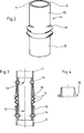
- the intermediate sleeve shown in FIG. 2 shows the design according to the application corresponding to FIG. 1.
- Fig. 3 shows a longitudinal section through an intermediate sleeve with a conical friction.
- the frictional engagement in the area 13 is achieved by the slotted conical clamping sleeve 15 and, as an example in the lower part, the frictional engagement in the area 12 is achieved by an annular bead 16 which is attached to the outer tube 8.
- FIG. 4 shows an embodiment of the tapered sleeve 15 used.
- FIG. 5 shows a modified embodiment of the object of the invention in that the intermediate sleeve 4 'consisting of the two nested tubes 7' and 8 'as a whole is slightly conical and its larger diameter D1 at the lower edge, the smaller diameter D 2 on the other hand has at the top.
- the diameters D 1 and D 2 are matched to one another in such a way that, for example, a cone with a gradient of 1:30 results.
- a corresponding cone has the lower connection area 3a of the carrier tube 3, to which, like FIG. 1, the traffic sign is fastened.
- the connection area 3a of the carrier tube 3 is pushed from above over the intermediate sleeve 4 in such a way that the intermediate sleeve 4 and the carrier tube 3 fit snugly into one another.
- the lower area of the intermediate sleeve 4 is in turn pushed over the connection area 6a of the receptacle 6, the area 6a in turn having a cone 1:30, the tip of which points upwards, so that the intermediate sleeve 4 'sits firmly on this cone part 6a.
- the outer tube 8 'has the corrugations 11 and it is just as in the embodiments of FIGS. 1 and 3 together with the inner tube so that it has the same bending resistance as the support tube 3.
- the conical connection area 3a of the carrier tube 3 is provided with an external annular reinforcement in the form of a reinforcing sleeve 20.
- This reinforcing sleeve 20 is pushed from the outside over the carrier tube 3, clamps on the lower conical region 3a and is additionally there either spot welded in a manner known per se or otherwise firmly and captively connected to the carrier tube 3.
- the inner tube 7 'of the intermediate sleeve 4' is also provided in the area of the reinforcing sleeve 20 with an inner reinforcing sleeve 21, which is somewhat higher than the reinforcing sleeve 20.
- the reinforcing sleeve 21 is also inserted from the inside into the inner tube and is firmly and captively connected to the inner tube 7 and thus to the intermediate sleeve 4 in a known manner, for example by spot welding.
- the structure of the traffic sign carrier of FIG. 5 is extremely simple. Namely, only the intermediate sleeve 4 'needs to be pushed onto the connection area 6a of the receptacle 6 from above. Due to the conical shape, it is stuck. The carrier tube 3 with the conical connection area 3a is then pushed from above over the intermediate sleeve 4 '. The carrier tube 3 with the traffic sign is stuck due to the conical design. A fuse, as with Fi g . 1 through the rivets 14 is possible, but not absolutely necessary, since there is a fairly good clamping fit with the weak cone chosen.
Landscapes
- Engineering & Computer Science (AREA)
- Architecture (AREA)
- Civil Engineering (AREA)
- Structural Engineering (AREA)
- Road Signs Or Road Markings (AREA)
Applications Claiming Priority (4)
| Application Number | Priority Date | Filing Date | Title |
|---|---|---|---|
| DE3225917 | 1982-07-10 | ||
| DE3225917 | 1982-07-10 | ||
| DE3314701 | 1983-04-22 | ||
| DE19833314701 DE3314701A1 (de) | 1982-07-10 | 1983-04-22 | Verkehrszeichentraeger |
Publications (2)
| Publication Number | Publication Date |
|---|---|
| EP0099070A2 true EP0099070A2 (fr) | 1984-01-25 |
| EP0099070A3 EP0099070A3 (fr) | 1985-04-24 |
Family
ID=25802986
Family Applications (1)
| Application Number | Title | Priority Date | Filing Date |
|---|---|---|---|
| EP83106634A Withdrawn EP0099070A3 (fr) | 1982-07-10 | 1983-07-07 | Support pour panneau ou signal de circulation |
Country Status (2)
| Country | Link |
|---|---|
| EP (1) | EP0099070A3 (fr) |
| DE (1) | DE3314701A1 (fr) |
Cited By (4)
| Publication number | Priority date | Publication date | Assignee | Title |
|---|---|---|---|---|
| GB2151677A (en) * | 1983-12-20 | 1985-07-24 | Geoffrey Lawson Norman Statham | Improvements in or relating to methods and apparatus for supporting tubular posts |
| EP0156158A1 (fr) * | 1984-03-14 | 1985-10-02 | Eberhard Hoeckle | Support pour panneau de signalisation |
| FR2868096A1 (fr) * | 2004-03-25 | 2005-09-30 | Hau Loic Guist | Attache de securite pour mobilier urbain |
| EP4675046A1 (fr) * | 2024-07-03 | 2026-01-07 | Katalysator of Kronoberg AB | Ensemble poteau d'etablissement de collision, liaison de retenue elastomere pour ensemble poteau et procede de protection contre les collisions pour poteau de signalisation |
Family Cites Families (16)
| Publication number | Priority date | Publication date | Assignee | Title |
|---|---|---|---|---|
| GB746810A (en) * | 1954-07-01 | 1956-03-21 | John Henry Ellinger | Improvements relating to the construction of tubular frameworks |
| CH413673A (fr) * | 1964-06-24 | 1966-05-15 | Leubaz Ernest | Borne de signalisation routière |
| US3381427A (en) * | 1965-10-23 | 1968-05-07 | George H. Watson | Frangible and expandable assembly for parking meter supports, stanchions, poles and posts |
| DE1658662A1 (de) * | 1967-08-17 | 1970-11-05 | Guenter Gubela | Leitpfosten aus thermoplastischem Kunststoff,der insbesondere als geblasener Koerper ausgebildet ist |
| DE6900659U (de) * | 1969-01-08 | 1969-08-21 | Vauth Sagel Kg | Leitpfahl fuer die strassenbegrenzung oder dergleichen |
| CH510789A (fr) * | 1969-05-16 | 1971-07-31 | Technoplast Sa | Potelet de balisage ou de signalisation pour route |
| AU447473B2 (en) * | 1970-08-05 | 1974-04-02 | The Commonwealth Industrial Gases Ltd | Improvements in devices for the control and direction of traffic |
| US3713262A (en) * | 1970-12-10 | 1973-01-30 | J Jatcko | Taper lock break-away pole structure |
| FR2140834A5 (fr) * | 1971-06-09 | 1973-01-19 | Garcia Pierre | |
| DE2150316A1 (de) * | 1971-10-08 | 1973-04-12 | Benninger Edgar | Verbindung fuer 2-teilige rohrartige staender fuer verkehrszeichen |
| FR2165299A5 (fr) * | 1971-12-24 | 1973-08-03 | Gmt Sa | |
| DE2309249A1 (de) * | 1973-02-24 | 1974-08-29 | Kurt Konrad Gustav Karl Nagl | Standsaeule mit verformungseinrichtung |
| US3913518A (en) * | 1974-05-28 | 1975-10-21 | Nathan W Kaplan | Traffic marker with resilient column |
| US4021977A (en) * | 1976-03-19 | 1977-05-10 | Foresight Industries | Reusable yielding post supports |
| DE2830875A1 (de) * | 1978-07-13 | 1979-10-31 | Vulkan Werk Gmbh | Signal- oder leuchtenmast fuer verkehrsflaechen |
| DE3042914A1 (de) * | 1980-11-14 | 1982-07-01 | Karl 3320 Salzgitter Schöngen | Rohrfoermiger standpfosten |
-
1983
- 1983-04-22 DE DE19833314701 patent/DE3314701A1/de not_active Withdrawn
- 1983-07-07 EP EP83106634A patent/EP0099070A3/fr not_active Withdrawn
Cited By (5)
| Publication number | Priority date | Publication date | Assignee | Title |
|---|---|---|---|---|
| GB2151677A (en) * | 1983-12-20 | 1985-07-24 | Geoffrey Lawson Norman Statham | Improvements in or relating to methods and apparatus for supporting tubular posts |
| EP0146401A3 (fr) * | 1983-12-20 | 1986-04-16 | Geoffrey Lawson Norman Stratham | Procédé et dispositif pour supporter des poteaux tubulaires |
| EP0156158A1 (fr) * | 1984-03-14 | 1985-10-02 | Eberhard Hoeckle | Support pour panneau de signalisation |
| FR2868096A1 (fr) * | 2004-03-25 | 2005-09-30 | Hau Loic Guist | Attache de securite pour mobilier urbain |
| EP4675046A1 (fr) * | 2024-07-03 | 2026-01-07 | Katalysator of Kronoberg AB | Ensemble poteau d'etablissement de collision, liaison de retenue elastomere pour ensemble poteau et procede de protection contre les collisions pour poteau de signalisation |
Also Published As
| Publication number | Publication date |
|---|---|
| DE3314701A1 (de) | 1984-01-12 |
| EP0099070A3 (fr) | 1985-04-24 |
Similar Documents
| Publication | Publication Date | Title |
|---|---|---|
| DE2711785C2 (de) | Halterung für Straßenleitpfosten od.dgl. | |
| DE60221737T2 (de) | Aufprallenergie verzehrende Struktur für ein Fahrzeug | |
| DE4034546C2 (de) | Halteelement aus Kunststoff | |
| EP0192913B1 (fr) | Cheville expansible à indication de serrage | |
| DE2814145C2 (de) | Halterungsvorrichtung zur Befestigung einer Lenksäule für Kraftfahrzeuge am Fahrzeugkörper | |
| EP0011199B1 (fr) | Dispositif de serrage | |
| DE2042640C3 (de) | Pfosten aus Kunststoff, insbesondere Straßenleitpfosten und Verfahren zu seiner Herstellung | |
| DE1912528B2 (de) | Sicherheitslenkrad für Kraftfahrzeuge | |
| DE3408612C2 (fr) | ||
| EP0156158A1 (fr) | Support pour panneau de signalisation | |
| DE3023411A1 (de) | Spreizanker | |
| DE3314701A1 (de) | Verkehrszeichentraeger | |
| DE10145446A1 (de) | Energieabsorbierende Konstruktion und damit versehenes Fahrzeug | |
| DE4104671A1 (de) | Abschleppvorrichtung an einem kraftfahrzeug | |
| DE2457498C3 (de) | Unterteilte Lenkwelle für ein Fahrzeug | |
| DE4437177B4 (de) | Befestigungselement, das ein Blechteil mit Gewindedurchzug umfaßt | |
| EP0955414B1 (fr) | Dispositif pour fixer des mats pour des feux de circulation ou similaires | |
| EP0899186A2 (fr) | Suspension élastique d'essieu pour véhicules à deux roues | |
| DE8311972U1 (de) | Verkehrszeichentraeger | |
| DE69715490T2 (de) | Verformbahres Rohr einer Handhabe für eine Fahrzeugtür | |
| DE10354386B3 (de) | Gummilager zur Lagerung eines Profilstabes | |
| DE8219817U1 (de) | Verkehrszeichentraeger | |
| DE29907513U1 (de) | Als Deformationsdämpfer ausgebildeter Pralldämpfer | |
| DE3411488A1 (de) | Bakenstaender | |
| DE3732546C1 (en) | Pipe-securing means and process for installing said pipe-securing means |
Legal Events
| Date | Code | Title | Description |
|---|---|---|---|
| PUAI | Public reference made under article 153(3) epc to a published international application that has entered the european phase |
Free format text: ORIGINAL CODE: 0009012 |
|
| AK | Designated contracting states |
Designated state(s): AT BE CH DE FR GB IT LI LU NL SE |
|
| PUAL | Search report despatched |
Free format text: ORIGINAL CODE: 0009013 |
|
| AK | Designated contracting states |
Designated state(s): AT BE CH DE FR GB IT LI LU NL SE |
|
| STAA | Information on the status of an ep patent application or granted ep patent |
Free format text: STATUS: THE APPLICATION IS DEEMED TO BE WITHDRAWN |
|
| 18D | Application deemed to be withdrawn |
Effective date: 19851224 |