EP0099272A2 - Schleifenschlusseinrichtung für Fernsprechleitung - Google Patents
Schleifenschlusseinrichtung für Fernsprechleitung Download PDFInfo
- Publication number
- EP0099272A2 EP0099272A2 EP83400325A EP83400325A EP0099272A2 EP 0099272 A2 EP0099272 A2 EP 0099272A2 EP 83400325 A EP83400325 A EP 83400325A EP 83400325 A EP83400325 A EP 83400325A EP 0099272 A2 EP0099272 A2 EP 0099272A2
- Authority
- EP
- European Patent Office
- Prior art keywords
- line
- circuit
- transistor
- loop circuit
- switch
- Prior art date
- Legal status (The legal status is an assumption and is not a legal conclusion. Google has not performed a legal analysis and makes no representation as to the accuracy of the status listed.)
- Ceased
Links
Images
Classifications
-
- H—ELECTRICITY
- H04—ELECTRIC COMMUNICATION TECHNIQUE
- H04M—TELEPHONIC COMMUNICATION
- H04M1/00—Substation equipment, e.g. for use by subscribers
- H04M1/26—Devices for calling a subscriber
- H04M1/30—Devices which can set up and transmit only one digit at a time
- H04M1/31—Devices which can set up and transmit only one digit at a time by interrupting current to generate trains of pulses; by periodically opening and closing contacts to generate trains of pulses
-
- H—ELECTRICITY
- H04—ELECTRIC COMMUNICATION TECHNIQUE
- H04M—TELEPHONIC COMMUNICATION
- H04M7/00—Arrangements for interconnection between switching centres
- H04M7/0096—Trunk circuits
Definitions
- the subject of the present invention is a loop circuit for a telephone line and, more particularly, a circuit for terminating a network line in a private telephone installation.
- a known solution consists in providing a loopback circuit of the line connected in parallel with the latter, the communication channel with the indoor station being decoupled by a transformer separating the private installation from the public network in direct current.
- This parallel loopback circuit must not weaken the speech currents. It must therefore have the characteristics of an inductor.
- a known method consists in using a gyrator dipole.
- a dipole is described in particular in French patent n ° 71 25013 filed on July 8, 1971.
- This dipole comprises a transistor whose collector is connected directly to a first terminal of the dipole, whose emitter is connected to the other terminal of the dipole by a resistor, and whose base electrode is connected to the first terminal by a resistor and to the other terminal of the dipole by through a capacitor.
- this dipole is equivalent to an inductance.
- the invention relates to a gyrator loop circuit in which the loop has a high and almost constant impedance at currents at voice frequencies.
- the charge of the gyrator's capacitor depends on the line voltage.
- the loop is open, the line tension varies. It is therefore important to protect the capacitor from such variations.
- the present invention therefore also relates to a circuit of the previously defined type in which the voltage across the capacitor is preserved from fluctuations in the voltage of the line in open loop.
- the loop circuit of the invention is characterized in that a switch is arranged to block the transistor on command and that another switch is arranged to disconnect from the rest of the circuit one of the armatures of the capacitor.
- Another characteristic of the loop circuit of the invention lies in the fact that the transistor of the gyrator • is produced according to the V-MOS technology.
- the first switch is an optocoupler comprising in particular a phototransistor whose emitter-collector circuit is connected between the transistor control electrode and the line wire which is connected to an electrode of the transistor via a resistor.
- the second switch is a bidirectional switch produced using two optocouplers whose transistors are mounted head to tail, in series with the capacitor.
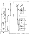
- the loop circuit LC of the appended figure is connected in parallel on the wires of a network line LR connecting a private telephone exchange BX to a public telephone exchange CX via a decoupling transformer TR.
- the line LR is connected to a call reception circuit RA by the rest contact rt of a relay RT.
- the circuit RA produces a signal sg.
- the answering machine is connected by the private exchange BX to the transformer TR, and a command signal sp applied to the call reception circuit RA energizes the relay RT.
- the rt contact operates and connects the network line LR to the transformer TR to establish the conversation path.
- the LR network line is looped on the LC loop circuit.
- the RT relay is energized in the same way.
- the LC loop circuit is connected to the network line LR via a rectifier bridge RB always imposing the same direction on the current in the LC loop circuit regardless of the polarity of the voltage.
- the LR network line The positive and negative outputs of the bridge RB are respectively connected to the inputs A and B of the loop circuit LC.
- This loop circuit notably includes a gyrator dipole consisting of a transistor Tl of the V-MOS type, a capacitor Cl and resistors R1 to R3.
- the drain electrode of transistor Tl is connected to input A of the loop circuit LC.
- the source electrode of this transistor is connected to the input B of the loop circuit LC via the resistor RI.
- the control electrode of the transistor Tl is connected to the common point of the resistors R2 and R3 connected in series between the inputs ' s A and B.
- a first armature of the capacitor Cl is connected to the control electrode of the transistor Tl, the other armature of this capacitor being connected to the source electrode of this transistor by means of a bidirectional switch SC1.
- the switch SC1 comprises a first optocoupler OC1 made up of a light-emitting diode LDI and a phototransistor TL1, and a second optocoupler OC2 made up of a light-emitting diode LD2 and a phototransistor TL2.
- the emitter of phototransistor TL1 and the collector of phototransistor TL2 are connected to the second armature of capacitor C1.
- the collector of phototransistor TL1 and the emitter of phototransistor TL2 are connected to input B of the LC loop circuit.
- the anode of the light-emitting diode LD1 is connected to a source of control signals cdl not shown.
- the cathode of this diode is connected to the anode of the diode LD2.
- the cathode of the latter is connected to the reference potential, ground for example.
- the loop circuit LC also includes a switch SC2 connected between the control electrode of the transistor Tl and the input B of the circuit.
- This switch SC2 is, according to the example chosen, an optocoupler comprising a phototransistor TL3 whose transmitter is connected to input B of the loop circuit LC and whose collector is connected to the control electrode of transistor Tl, and a light-emitting diode LD3 whose cathode is connected to ground and whose anode receives signals from cd2 command.
- the LC loop circuit further comprises a regulating thermistor R4 connected in parallel with the resistor RI, and a Zener-effect protection diode Zl whose anode is connected to the source electrode of transistor Tl and whose cathode is connected to input A.
- a cd2 level 0 control signal is supplied to the anode of the diode LD3 which is blocked.
- the switch SC2 opens and the transistor Tl conducts. Simultaneously, the switch SC1 is closed by the control signal cdl at level 1. Thanks to the presence of two head-to-tail transistors, the capacitor Cl is included in the circuit for both directions of the current.
- the gyrating dipole Tl-Cl-Rl-R2 then functions normally: it ensures the continuous looping of the LR line.
- the speech signals transmitted on this line are not weakened by the dipole which is equivalent in alternation to an inductance of high value.
- the loop circuit allows the transmission of pulses in the form of loop openings.
- Each opening of the loop is obtained by sending a control signal cd2 at level 1.
- the diode LD3 is turned on and the switch SC2 closes and connects the control electrode of the transistor Tl to the input B of the LC loop circuit. The transistor Tl is blocked.
- the opening of the switch SCl is controlled by sending a control signal cdl of level 0.
- the second armature of the capacitor Cl is then isolated from the rest of the circuit. In this way, the capacitor CI retains its charge during the pulse. After the pulse, it is reconnected to transistor Tl and the loop is restored without disturbance.
- the loop circuit LC therefore makes it possible to loop the telephone line LR without weakening the speech currents. It also allows the transmission of pulses (numbering, for example) in the form of loop openings.
Landscapes
- Engineering & Computer Science (AREA)
- Signal Processing (AREA)
- Interface Circuits In Exchanges (AREA)
- Telephonic Communication Services (AREA)
- Sub-Exchange Stations And Push- Button Telephones (AREA)
- Telephone Function (AREA)
- Communication Cables (AREA)
Applications Claiming Priority (2)
| Application Number | Priority Date | Filing Date | Title |
|---|---|---|---|
| FR8211898 | 1982-07-07 | ||
| FR8211898A FR2530105B1 (fr) | 1982-07-07 | 1982-07-07 | Circuit de boucle pour ligne telephonique |
Publications (2)
| Publication Number | Publication Date |
|---|---|
| EP0099272A2 true EP0099272A2 (de) | 1984-01-25 |
| EP0099272A3 EP0099272A3 (de) | 1984-11-07 |
Family
ID=9275759
Family Applications (1)
| Application Number | Title | Priority Date | Filing Date |
|---|---|---|---|
| EP83400325A Ceased EP0099272A3 (de) | 1982-07-07 | 1983-02-16 | Schleifenschlusseinrichtung für Fernsprechleitung |
Country Status (15)
| Country | Link |
|---|---|
| US (1) | US4535202A (de) |
| EP (1) | EP0099272A3 (de) |
| JP (1) | JPS5962289A (de) |
| KR (1) | KR860001329B1 (de) |
| AU (1) | AU554170B2 (de) |
| BR (1) | BR8303407A (de) |
| CA (1) | CA1206646A (de) |
| DK (1) | DK241583A (de) |
| FR (1) | FR2530105B1 (de) |
| GR (1) | GR78898B (de) |
| IN (1) | IN159070B (de) |
| NO (1) | NO831050L (de) |
| NZ (1) | NZ204604A (de) |
| PT (1) | PT76601B (de) |
| ZA (1) | ZA832714B (de) |
Cited By (1)
| Publication number | Priority date | Publication date | Assignee | Title |
|---|---|---|---|---|
| AT393056B (de) * | 1985-04-03 | 1991-08-12 | Alcatel Austria Ag | Uebertragerschaltung fuer fernsprechnetze |
Families Citing this family (7)
| Publication number | Priority date | Publication date | Assignee | Title |
|---|---|---|---|---|
| US4564770A (en) * | 1983-03-29 | 1986-01-14 | Rca Corporation | Solid state relay with fast turnoff |
| GB2220820B (en) * | 1988-07-13 | 1992-07-08 | Philips Electronic Associated | Telephone line loop current regulator |
| JPH05176354A (ja) * | 1991-12-20 | 1993-07-13 | Fujitsu Ltd | 加入者インタフェース回路 |
| US5621731A (en) * | 1994-02-04 | 1997-04-15 | Omnilink Communications Corporation | Private exchange for ISDN |
| WO1995021485A1 (en) * | 1994-02-04 | 1995-08-10 | Adak Communications Corporation | Power supply for private branch exchange |
| CA2146596C (en) * | 1994-04-29 | 1999-09-21 | Harry W. Moore, Iii | Loop current detector |
| WO2009134151A1 (en) * | 2008-04-29 | 2009-11-05 | The University Of Waikato | Digital control for controlling and linearizing an ac impedance |
Family Cites Families (7)
| Publication number | Priority date | Publication date | Assignee | Title |
|---|---|---|---|---|
| BE786341A (fr) * | 1971-07-08 | 1973-01-17 | Int Standard Electric Corp | Circuit gyrateur a limitation de courant |
| US3801837A (en) * | 1972-12-07 | 1974-04-02 | Eaton Corp | Photocoupling line isolation |
| FR2251975B1 (de) * | 1973-11-16 | 1979-08-03 | Labo Cent Telecommunicat | |
| US3987319A (en) * | 1974-12-05 | 1976-10-19 | The United States Of America As Represented By The Secretary Of The Army | Radiation-activated sensor |
| FR2315811A1 (fr) * | 1975-06-27 | 1977-01-21 | Labo Cent Telecommunicat | Dipole electronique pour le bouclage d'une ligne telephonique |
| US4282604A (en) * | 1979-04-04 | 1981-08-04 | Jefferson William T | Optical isolation circuit for bidirectional communication lines |
| US4476351A (en) * | 1982-03-25 | 1984-10-09 | Rockwell International Corporation | Subscriber loop current regulator |
-
1982
- 1982-07-07 FR FR8211898A patent/FR2530105B1/fr not_active Expired
-
1983
- 1983-02-16 EP EP83400325A patent/EP0099272A3/de not_active Ceased
- 1983-03-24 NO NO831050A patent/NO831050L/no unknown
- 1983-04-18 ZA ZA832714A patent/ZA832714B/xx unknown
- 1983-04-27 PT PT76601A patent/PT76601B/pt unknown
- 1983-05-27 DK DK241583A patent/DK241583A/da not_active Application Discontinuation
- 1983-06-16 NZ NZ204604A patent/NZ204604A/en unknown
- 1983-06-21 AU AU15974/83A patent/AU554170B2/en not_active Ceased
- 1983-06-27 BR BR8303407A patent/BR8303407A/pt unknown
- 1983-06-30 US US06/509,789 patent/US4535202A/en not_active Expired - Fee Related
- 1983-06-30 KR KR1019830002987A patent/KR860001329B1/ko not_active Expired
- 1983-07-04 GR GR71856A patent/GR78898B/el unknown
- 1983-07-06 CA CA000431953A patent/CA1206646A/en not_active Expired
- 1983-07-06 JP JP58123103A patent/JPS5962289A/ja active Pending
- 1983-07-07 IN IN841/CAL/83A patent/IN159070B/en unknown
Cited By (1)
| Publication number | Priority date | Publication date | Assignee | Title |
|---|---|---|---|---|
| AT393056B (de) * | 1985-04-03 | 1991-08-12 | Alcatel Austria Ag | Uebertragerschaltung fuer fernsprechnetze |
Also Published As
| Publication number | Publication date |
|---|---|
| JPS5962289A (ja) | 1984-04-09 |
| DK241583A (da) | 1984-01-08 |
| CA1206646A (en) | 1986-06-24 |
| PT76601B (fr) | 1985-12-10 |
| GR78898B (de) | 1984-10-02 |
| US4535202A (en) | 1985-08-13 |
| BR8303407A (pt) | 1984-02-07 |
| FR2530105A1 (fr) | 1984-01-13 |
| AU1597483A (en) | 1984-01-12 |
| NO831050L (no) | 1984-01-09 |
| PT76601A (fr) | 1983-05-01 |
| EP0099272A3 (de) | 1984-11-07 |
| AU554170B2 (en) | 1986-08-07 |
| NZ204604A (en) | 1985-10-11 |
| DK241583D0 (da) | 1983-05-27 |
| ZA832714B (en) | 1984-02-29 |
| KR860001329B1 (ko) | 1986-09-13 |
| KR840005637A (ko) | 1984-11-14 |
| FR2530105B1 (fr) | 1985-07-05 |
| IN159070B (de) | 1987-03-21 |
Similar Documents
| Publication | Publication Date | Title |
|---|---|---|
| US4723267A (en) | Telephone line interface and dialer circuitry for telecommunications equipment | |
| FR2504332A1 (fr) | Systeme de limitation d'appels sortant d'un standard par reconnaissance vocale | |
| FR2542548A1 (fr) | Circuit d'interface de ligne telephonique | |
| EP0403999B1 (de) | Analoge Verbindungsschaltung für eine Fernsprechnebenstellenanlage | |
| FR2530105A1 (fr) | Circuit de boucle pour ligne telephonique | |
| EP0127517B1 (de) | Verbindungssatz für Amtsleitungseinheit | |
| CN1192591C (zh) | 用于辅助设备的由电话线供电的电源及其操作方法 | |
| FR2590430A1 (fr) | Joncteur pour systeme telephonique | |
| JPS6321385B2 (de) | ||
| EP0150886B1 (de) | Perifernsprechsystem für Fernsprechapparat und Perifernsprechapparate | |
| EP0419363B1 (de) | Impulswahleinrichtung für ein an eine Fernsprechleitung angeschlossenes Gerät | |
| EP0082749B1 (de) | Teleterminal verbunden mit zwei Telefonleitungen und mit teilweiser Fernspeisung | |
| BE1005335A0 (fr) | Dispositif d'aiguillage d'appels telephoniques vers un telecopieur ou vers un poste telephonique. | |
| US4841566A (en) | Hold and dial accessory for telephone instrument | |
| EP0724349B1 (de) | Verfahren und Gerät zur Fernübertragung eines paralellen Abhöranrufs auf einer Fernsprechleitung | |
| CA1088686A (en) | Tone applying line circuit | |
| EP0632639B1 (de) | Facsimilegerät mit Netzschleifenstromsteuerung | |
| FR2500698A1 (fr) | Dispositif anti-effet larsen pour poste telephonique | |
| EP0302957A1 (de) | Anordnung zur Berichtsmeldung in einem Fernsprechsystem | |
| FR2508744A1 (fr) | Poste telephonique a clavier et a ecoute amplifiee | |
| FR2487611A1 (fr) | Circuit d'interface de clavier a frequences vocales | |
| FI56463C (fi) | Anordning foer avkoppling av signaler fraon abonnentens telefonledning | |
| SU1195476A1 (ru) | Устройство распознавания вызова | |
| EP1492312B1 (de) | Vorrichtung zur Erzeugung von durch Telephoniebenutzer vernehmbaren Alarmen | |
| GB2126045A (en) | Subscriber carrier system |
Legal Events
| Date | Code | Title | Description |
|---|---|---|---|
| PUAI | Public reference made under article 153(3) epc to a published international application that has entered the european phase |
Free format text: ORIGINAL CODE: 0009012 |
|
| AK | Designated contracting states |
Designated state(s): AT BE DE FR GB IT LU NL SE |
|
| PUAL | Search report despatched |
Free format text: ORIGINAL CODE: 0009013 |
|
| AK | Designated contracting states |
Designated state(s): AT BE DE FR GB IT LU NL SE |
|
| 17P | Request for examination filed |
Effective date: 19841226 |
|
| 17Q | First examination report despatched |
Effective date: 19860507 |
|
| STAA | Information on the status of an ep patent application or granted ep patent |
Free format text: STATUS: THE APPLICATION HAS BEEN REFUSED |
|
| 18R | Application refused |
Effective date: 19861031 |
|
| RIN1 | Information on inventor provided before grant (corrected) |
Inventor name: MEUNIER, BERNARD MARIE ANDRE |