EP0150886B1 - Perifernsprechsystem für Fernsprechapparat und Perifernsprechapparate - Google Patents
Perifernsprechsystem für Fernsprechapparat und Perifernsprechapparate Download PDFInfo
- Publication number
- EP0150886B1 EP0150886B1 EP85200084A EP85200084A EP0150886B1 EP 0150886 B1 EP0150886 B1 EP 0150886B1 EP 85200084 A EP85200084 A EP 85200084A EP 85200084 A EP85200084 A EP 85200084A EP 0150886 B1 EP0150886 B1 EP 0150886B1
- Authority
- EP
- European Patent Office
- Prior art keywords
- bus
- conductor
- signal
- transmitting
- telephone
- Prior art date
- Legal status (The legal status is an assumption and is not a legal conclusion. Google has not performed a legal analysis and makes no representation as to the accuracy of the status listed.)
- Expired
Links
Images


Classifications
-
- H—ELECTRICITY
- H04—ELECTRIC COMMUNICATION TECHNIQUE
- H04M—TELEPHONIC COMMUNICATION
- H04M1/00—Substation equipment, e.g. for use by subscribers
- H04M1/71—Substation extension arrangements
- H04M1/715—Substation extension arrangements using two or more extensions per line
Definitions
- the present invention relates to a peritelephony system comprising a subscriber telephone set connected to a subscriber line, at least one peritelephony device and means of connection between said set and the device (s) for peritelephony. to the performance of system functions.
- connection means between a subscriber telephone set and a peritelephony device are, for example, the transfer of speech signals and information signals, or of an electrical reference signal and of power supply function.
- connection means between the telephone set and the peritelephony device consist of a line with two conductors to which the peritelephony devices are connected.
- the destination of the line information is determined by address data which is transmitted with this information.
- each peritelephony device must be provided with at least one interface circuit and one processing unit.
- connection means are in the form of a bus comprising several conductors, each conductor being intended for a single system function and each system function being supported. by a single bus driver.
- a bus The operation of a bus is well known in the computer industry; it consists in transmitting signals in a transmission channel with several lines so that each signal present on one of the lines is exactly repeated at any point of said line; thus all the devices connected to the bus have the same view of the state of each line of the bus, that is to say of the state of the bus; of course, for each line of the bus, each connected device can be a signal transmitter and / or receiver.
- connection by means of a bus therefore makes it possible to connect a plurality of peritelephony devices all having the same information transmitted by the bus; the implementation, simultaneous or not, of the telephone set and of the peritelephony devices connected to the bus can therefore be carried out in a concerted manner to avoid conflicts and / or - false maneuvers which would cause improper use of the telephone line .
- the bus should transmit the necessary and sufficient signals for all peritelephony applications.
- the telephone set then has, in addition to its known functions, an interface function between the telephone line and the information bus common to all the connected devices; to this end, according to the invention, said telephone set is particularly remarkable in that it comprises connection means for connect to said bus in particular: an OR gate circuit whose output controls said activation device and whose first input is connected to said internal two-state control device and whose second input is connected to said fifth bus conductor for receiving an external line seizure command signal, and thus activating the activation device whatever the origin, internal and / or external, of the line seizure command.
- Said six-conductor bus connected to a telephone set as above allows in particular the connection of a peritelephony device of the answering and recording type.
- the telephone set must have a loop opening device to open the loop to control a control signal which generally comes from a dialing circuit associated with a dial, or a keyboard, well known in telephone sets.
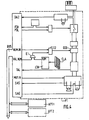
- FIG. 1 are shown schematically devices peritelephony (APT1, APT2, ...) connected to the bus (BUS) which is also connected to a telephone set (PT).
- the telephone set (PT) is connected to a telephone line by a connection device (RA), for example a contactor of current model.
- RA connection device
- the telephone set thus described is a minimum post which only allows, by itself, to answer a call; it does not allow you to make a call since it does not have a dialing circuit.
- this type of station may very well be sufficient for slave applications of the remote control peritelephony type.
- a connector with at least 6 pins (CA6), known and symbolically represented, can be used.
- connections are made with known means, wiring or other, with possible insertion of known means of protection and / or isolation of the resistor, capacitor, etc. type, depending on the nature, logic or analog, transmitted signals.
- an OR gate (01) for combining on the one hand the control signal from said internal control device (DCI), and on the other hand the external line-take command signal from the bus driver (PDL), so that the activation device (DA) is in the active state, whatever the origin of the line-take command this origin can be either internal, off-hook condition of the above-mentioned internal control device, or external, line seizure signal (PDL) active from a peritelephony device.
- connection mode of the bus conductors are represented on the one hand in the telephone set (PT) and on the other hand in the peritelephony devices (APT1, APT2).
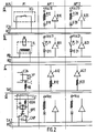
- FIG 2a illustrates a driver connection mode (FCH);
- the internal control device (DCI) is often a simple switch, mechanical or other electrical, which, in the hooked state provides, or does not deliver, any energy; to know its status, hooked or unhooked, the power supply (VCC 10) of the peritelephony device (APT1) is connected to the conductor (FCH) via a resistor (R10) and a diode (D10); thus in the hooked state, switch open, the conductor (FCH) is at the supply voltage (VCC 10) while in the hooked state, switch closed, the conductor (FCH) is at the voltage of reference (REF); it then suffices to test the conductor voltage (FCH) by means of a voltage buffer (B10) so that the device (APT1) knows the state of the internal control device (DCI); the connection of the device (APT2) is, for example, similar, with a power supply (VCC20), a resistor (R20), a diode (D20) and a
- FIG. 2b illustrates a mode of connection of the conductor (PDL), the external line seizure control signal can be generated in any peritelephony device for example by means of a switch (PL11, PL21) supplied by a voltage ( VCC 11, VCC 21 which can be the same as VCC 10, VCC 20) and connected to the conductor (PDL) via a diode (D11, D21) to avoid conflicts between the power supplies (VCC) as mentioned above; in the telephone set, the signal (PDL) could be directly connected to the input of the above-mentioned OR gate (01) as above, but it is preferable, for safety reasons, to introduce electrical insulation, for example ' as shown by means of a relay (RL), between the telephone set and the bus.
- a relay RL
- Voltage buffers (B11, B21) allow each peritelephony device to know the state of the driver (PDL).
- Figure 2c illustrates a driver connection mode (SAS); inside the telephone set it is preferable, between the loudspeaker (HP) and the bus, to implement a resistor (RE) and a capacitor (C) to eliminate a possible DC component of the analog signal leaving the converter 2 sons / 4 sons as above; the reception of the signal in a peritelephony device can be carried out for example with a resistor (R12, R22) and an amplifier (A12, A22) or any other suitable means depending on the specificity of each peritonephony device.
- SAS driver connection mode
- FIG. 2d illustrates a mode of connection of the conductor (DA2); the call detection device (DDA) of the telephone set (PT) activates, in the event of a call on the telephone line (LT), an optocoupler (OPT); a capacitor (CAP) is connected between the connections of the opto-coupler to filter the ripples of the current similar to the ripples of the ringing call as aforesaid; the supply of the opto-coupler and the test of its state, call or non-call of the same kind as the known intermittent ringing, can be carried out, for example with means of the same kind as in FIG. 2a) already described, and as shown in Figure 2 d).
- connection means described by way of nonlimiting example in FIG. 2 are well known to those skilled in the art of electronics and / or the telephone who will have noted that the invention resides more in the principle of the bus, who advantageously replaces the aforementioned known nesting sockets, and in the choice of signals transmitted in the bus conductors.
- the bus should be "enriched" with an additional conductor (s) to transmit other signals.
- each peritelephony device can have an external power supply; this supply can come either from unrepresented means, electric batteries or other, arranged in the telephone set or from a line current which is recovered by said regulation device (RCC), as shown, from the available energy on the phone line.
- RRC regulation device
- said telephone set when on the one hand said telephone set (FIG. 3) further comprises a loop opening device (DOB) for opening the loop on command of a control signal and on the other hand the said 2-wire / 4-wire converter, further comprises a muting control input to inhibit the audio input (E) of the 2-wire / 4-wire converter
- said bus further comprises two additional conductors to transmit, from at least one peritelephony device, respectively a first control signal (NUM-IN) to control said loop opening device (DOB) and a second control signal called external mute (MUT) -IN) to control the so-called 2-wire / 4-wire converter mute (C24).
- a peritelephony device comprising a dialing circuit for generating a dialing control signal by loop opening
- automatic call applications for example alarm call for the elderly
- the connection bus allows a peritelephony device, on command of a simple push button for urgent call, to carry out a) line seizure via (PDL), b) automatic call of a pre number -registered via (NUM-IN + MUT-IN), c) sending of pre-recorded SOS message via the driver (SAE); operations a, b, c, being commanded and controlled by an automaton, for example microprogrammed, of the peritelephony device for alarm call.
- PDL line seizure via
- NUM-IN + MUT-IN pre number -registered via
- SAE pre-recorded SOS message
- the peritelephony device will position the mute signal (MUT-IN) in the active position for the entire time necessary for dialing (NUM-IN).
- a peritelephony device connected to said bus and comprising a control automaton, for example microprogrammed can perform dialing by loop opening by activating on the one hand the conductor (NUM-IN) and on the other hand, the conductor ( VAL-NUM) to ensure that there is no other simultaneous dialing from the telephone set; of course it would have been necessary beforehand, as aforesaid, that the peritelephony device performs line seizure (PDL) and all other operations that are functionally desirable and made possible in particular using the signals transmitted by the bus according to the invention.
- PDL line seizure
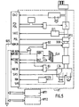
- NUM-OUT an additional conductor (NUM-OUT), FIG. 5, to transmit, from the telephone set, the said loop opening control signal (NUM) generated by the internal numbering circuit (ICN).
- a peritelephony device connected to the bus will be able to observe, for recording for example, the numbers called either by the telephone set (NUM-OUT) or by any peritelephony device (NUM-IN).
- the conductor (NUM-OUT) is connected to the output (NUM) of the internal numbering circuit (ICN) which is a preferred embodiment.
- the internal numbering circuit comprises an output (MUT), FIG. 5, of the internal mute control signal
- an additional conductor MUT-OUT
- an OR gate circuit (03) whose output is connected to the mute control input of the 2-wire / 4-wire converter (C24) and whose first input is connected to the conductor of the bus transmitting said external mute control signal (MUT-IN) and the second input of which is connected to said internal mute control signal (MUT).
- the mute device is thus controlled either by the internal numbering circuit (ICN), or by a command (MUT-IN) from a peritelephony device; any peritelephony device may, for example, include means for deferring a line seizure (PDL) and / or dialing (NUM-IN) command when the conductor (MUT-OUT) is active.
- ICN internal numbering circuit
- MUT-IN command from a peritelephony device
- any peritelephony device may, for example, include means for deferring a line seizure (PDL) and / or dialing (NUM-IN) command when the conductor (MUT-OUT) is active.
- PDL line seizure
- NUM-IN dialing
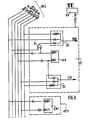
- FIG. 6 is shown by way of nonlimiting example, as in FIG. 2, an example of connection mode on the one hand of the elements already described, the same references are used, in FIG. 5 for the telephone set ( PT) and on the other hand the elements, described below, of a peritelephony device (APT1) with its own numbering circuit (ICN1) for transmitting a numbering signal (NUM1) in the conductor (NUM-IN) from the bus and to output a mute control signal (MUT 1) into the conductor (MUT-IN) of the bus; some resistors and safety diodes, not referenced but represented according to the uses, appear for information only and not limitative.
- APT1 peritelephony device
- ICN1 peritelephony device
- MUT 1 mute control signal
- a tone detector is a device which reacts in a known manner to the conventional tone frequency which is a continuous sound, that is to say a non-clocked sound, at the frequency of 440 Hz according to the usual standards.
- TAX additional conductor
- DIT tax pulse detector
- the telephone set includes a known polarity detector (DPO) of the telephone line to generate a polarity signal, to provide an additional conductor (POL) to transmit, from the telephone set, the said polarity signal .
- DPO polarity detector
- POL additional conductor
Landscapes
- Engineering & Computer Science (AREA)
- Signal Processing (AREA)
- Telephonic Communication Services (AREA)
- Small-Scale Networks (AREA)
- Telephone Function (AREA)
Claims (11)
eine ODER-Torschaltung, deren Ausgang die Aktivierungsanordnung steuert und von der ein erster Eingang mit der Zweizustände-Innensteueranordnung verbunden ist und ein zweiter Eingang mit dem fünften Leiter des Busses verbunden ist zum Erhalten eines Leitungsklemmen-Aussensteuersignals und zum Aktivieren der Aktivierungsanordnung unabhängig von der Frage, woher, von drinnen und/oder von draussen, die Steuerung der Leitungsklemme herrührt.
Applications Claiming Priority (2)
| Application Number | Priority Date | Filing Date | Title |
|---|---|---|---|
| FR8401554A FR2559007B1 (fr) | 1984-02-01 | 1984-02-01 | Systeme et moyens de connexion et de communication pour poste telephonique et appareils de peritelephonie |
| FR8401554 | 1984-02-01 |
Publications (3)
| Publication Number | Publication Date |
|---|---|
| EP0150886A2 EP0150886A2 (de) | 1985-08-07 |
| EP0150886A3 EP0150886A3 (en) | 1985-08-28 |
| EP0150886B1 true EP0150886B1 (de) | 1988-09-28 |
Family
ID=9300672
Family Applications (1)
| Application Number | Title | Priority Date | Filing Date |
|---|---|---|---|
| EP85200084A Expired EP0150886B1 (de) | 1984-02-01 | 1985-01-28 | Perifernsprechsystem für Fernsprechapparat und Perifernsprechapparate |
Country Status (5)
| Country | Link |
|---|---|
| US (1) | US4685121A (de) |
| EP (1) | EP0150886B1 (de) |
| JP (1) | JPS60200674A (de) |
| DE (1) | DE3565353D1 (de) |
| FR (1) | FR2559007B1 (de) |
Families Citing this family (6)
| Publication number | Priority date | Publication date | Assignee | Title |
|---|---|---|---|---|
| AU600213B2 (en) * | 1987-07-16 | 1990-08-02 | Octel Communications Corporation | Feature telephone integration device |
| US4873718A (en) * | 1987-07-16 | 1989-10-10 | Octel Communications Corp. | Feature telephone integration device |
| US5222124A (en) * | 1991-02-28 | 1993-06-22 | Vmc Systems, Inc. | PBX system communications device |
| DE69323661T2 (de) * | 1992-07-17 | 1999-07-22 | Siemens Business Communication Systems, Inc. (N.D.Ges.D.Staates Delaware), Santa Clara, Calif. | Verfahren und Vorrichtung zur Verbindung von Zusatzvorrichtungen mit einem digitalen Telefon |
| US5349640A (en) * | 1993-06-24 | 1994-09-20 | Rolm Company | Option bus adapter |
| KR0128170B1 (ko) * | 1994-10-08 | 1998-04-10 | 김광호 | 디지탈 키폰시스템에서 디지털 키폰전화기 접속장치 및 방법 |
Family Cites Families (12)
| Publication number | Priority date | Publication date | Assignee | Title |
|---|---|---|---|---|
| US3937889A (en) * | 1973-01-15 | 1976-02-10 | Sperry Rand Corporation | Data communication apparatus for use in a telephone system |
| US4410767A (en) * | 1976-05-17 | 1983-10-18 | Iwasaki Tsushinki Kabushiki Kaisha | Key telephone system |
| DE2917570B1 (de) * | 1979-04-30 | 1980-05-14 | Telefonbau & Normalzeit Gmbh | Schaltungsanordnung fuer eine digitale Fernsprechteilnehmerstation |
| CA1166777A (en) * | 1981-03-23 | 1984-05-01 | Gordon D. Benning | Home telephone exchange |
| EP0074319B1 (de) * | 1981-10-14 | 1985-07-03 | In Electronic, S.A.R.L. | Fernsprechapparat |
| JPS58151765A (ja) * | 1982-03-05 | 1983-09-09 | Nippon Telegr & Teleph Corp <Ntt> | デイジタル電話機 |
| JPS58213597A (ja) * | 1982-06-05 | 1983-12-12 | Nitsuko Ltd | ボタン電話装置 |
| JPS592123A (ja) * | 1982-06-29 | 1984-01-07 | Fujitsu Ltd | 電話端末機器制御方式 |
| DE3228210A1 (de) * | 1982-07-28 | 1984-02-02 | Siemens AG, 1000 Berlin und 8000 München | Sichtschirmtelefon |
| US4491690A (en) * | 1983-02-22 | 1985-01-01 | Daley Ronald J | Remote control system for use with a telephone |
| US4551832A (en) * | 1983-12-02 | 1985-11-05 | United Technologies Corporation | Telephone based control system |
| US4571455A (en) * | 1983-12-06 | 1986-02-18 | Yoram Labock | Electronic monitoring system particularly useful as an electronic babysitter |
-
1984
- 1984-02-01 FR FR8401554A patent/FR2559007B1/fr not_active Expired
-
1985
- 1985-01-28 EP EP85200084A patent/EP0150886B1/de not_active Expired
- 1985-01-28 DE DE8585200084T patent/DE3565353D1/de not_active Expired
- 1985-02-01 US US06/697,353 patent/US4685121A/en not_active Expired - Fee Related
- 1985-02-01 JP JP60018482A patent/JPS60200674A/ja active Pending
Also Published As
| Publication number | Publication date |
|---|---|
| JPS60200674A (ja) | 1985-10-11 |
| EP0150886A3 (en) | 1985-08-28 |
| FR2559007A1 (fr) | 1985-08-02 |
| EP0150886A2 (de) | 1985-08-07 |
| US4685121A (en) | 1987-08-04 |
| FR2559007B1 (fr) | 1987-10-09 |
| DE3565353D1 (en) | 1988-11-03 |
Similar Documents
| Publication | Publication Date | Title |
|---|---|---|
| US5471522A (en) | Telephone line sharing for a personal computer system | |
| EP0374828B1 (de) | Fernsprech-Anschlussanordnung für einen Personal-Computer und eine Einrichtung dafür | |
| EP0684722B1 (de) | Umlenkschnittstelle zwischen zwei Fernsprechleitungen und einer Fernsprechstelle | |
| JPH06284217A (ja) | インタフェース装置 | |
| FR2602942A1 (fr) | Appareil de communication de donnees connecte a une ligne telephonique | |
| CN1191046A (zh) | 具有挂机数字音频信息传送的电力线电话通信系统 | |
| US5309508A (en) | Apparatus and method for automatically blocking the transmission of identifying information concerning a telephone calling party | |
| EP0150886A2 (de) | Perifernsprechsystem für Fernsprechapparat und Perifernsprechapparate | |
| EP1203485A2 (de) | Fernsteuerung von telekommunikations- oder rechnergesteuerten geräten mittels kurzmitteilungen | |
| FR2601835A1 (fr) | Dispositif d'acces a un reseau telephonique | |
| GB2287610A (en) | Telecommunication systems | |
| EP0571518B1 (de) | Multikommunikations-Faksimilegerät | |
| EP1280325A4 (de) | Beantwortungseinrichtung und damit kommunizierendes kommunikationsgerät und dessen programm aufzeichnendes aufzeichnungsmedium und programm | |
| EP0551950B1 (de) | Videotext- und Faksimilegerät | |
| BE1005335A0 (fr) | Dispositif d'aiguillage d'appels telephoniques vers un telecopieur ou vers un poste telephonique. | |
| EP0724349B1 (de) | Verfahren und Gerät zur Fernübertragung eines paralellen Abhöranrufs auf einer Fernsprechleitung | |
| JP2826105B2 (ja) | 回線切換装置 | |
| EP0433153A1 (de) | Mit einem Fernsprechnetz verbindbares Endgerät zur Fernmeldung und Verwaltung und Apparat zur automatischen Wahl für ein solches Endgerät | |
| EP0578070A1 (de) | Fernmeldegerät sowie Faksimilegerät | |
| GB2014826A (en) | Telephone intruder alarm system | |
| JP3042937B2 (ja) | 自動検針システム | |
| JPS5945752A (ja) | 回線状態監視回路 | |
| JP3478941B2 (ja) | 電話回線−ネットワーク中継装置 | |
| EP1492312B1 (de) | Vorrichtung zur Erzeugung von durch Telephoniebenutzer vernehmbaren Alarmen | |
| JP2000307684A (ja) | 電話機アダプタ装置 |
Legal Events
| Date | Code | Title | Description |
|---|---|---|---|
| PUAI | Public reference made under article 153(3) epc to a published international application that has entered the european phase |
Free format text: ORIGINAL CODE: 0009012 |
|
| PUAL | Search report despatched |
Free format text: ORIGINAL CODE: 0009013 |
|
| AK | Designated contracting states |
Designated state(s): DE FR GB SE |
|
| AK | Designated contracting states |
Designated state(s): DE FR GB SE |
|
| 17P | Request for examination filed |
Effective date: 19860217 |
|
| 17Q | First examination report despatched |
Effective date: 19870513 |
|
| GRAA | (expected) grant |
Free format text: ORIGINAL CODE: 0009210 |
|
| AK | Designated contracting states |
Kind code of ref document: B1 Designated state(s): DE FR GB SE |
|
| REF | Corresponds to: |
Ref document number: 3565353 Country of ref document: DE Date of ref document: 19881103 |
|
| GBT | Gb: translation of ep patent filed (gb section 77(6)(a)/1977) | ||
| REG | Reference to a national code |
Ref country code: FR Ref legal event code: TP |
|
| REG | Reference to a national code |
Ref country code: FR Ref legal event code: TP Ref country code: FR Ref legal event code: CD |
|
| PLBE | No opposition filed within time limit |
Free format text: ORIGINAL CODE: 0009261 |
|
| 26N | No opposition filed | ||
| REG | Reference to a national code |
Ref country code: FR Ref legal event code: CD |
|
| PGFP | Annual fee paid to national office [announced via postgrant information from national office to epo] |
Ref country code: SE Payment date: 19920131 Year of fee payment: 8 |
|
| PG25 | Lapsed in a contracting state [announced via postgrant information from national office to epo] |
Ref country code: SE Effective date: 19930129 |
|
| PGFP | Annual fee paid to national office [announced via postgrant information from national office to epo] |
Ref country code: FR Payment date: 19940126 Year of fee payment: 10 |
|
| PGFP | Annual fee paid to national office [announced via postgrant information from national office to epo] |
Ref country code: DE Payment date: 19940330 Year of fee payment: 10 |
|
| PGFP | Annual fee paid to national office [announced via postgrant information from national office to epo] |
Ref country code: GB Payment date: 19941228 Year of fee payment: 11 |
|
| EUG | Se: european patent has lapsed |
Ref document number: 85200084.3 Effective date: 19930810 |
|
| PG25 | Lapsed in a contracting state [announced via postgrant information from national office to epo] |
Ref country code: FR Effective date: 19950929 |
|
| REG | Reference to a national code |
Ref country code: FR Ref legal event code: ST |
|
| PG25 | Lapsed in a contracting state [announced via postgrant information from national office to epo] |
Ref country code: DE Effective date: 19951201 |
|
| PG25 | Lapsed in a contracting state [announced via postgrant information from national office to epo] |
Ref country code: GB Effective date: 19960128 |
|
| GBPC | Gb: european patent ceased through non-payment of renewal fee |
Effective date: 19960128 |