EP0099314A2 - Device preventing the accumulation of earth at a disc mower housing - Google Patents
Device preventing the accumulation of earth at a disc mower housing Download PDFInfo
- Publication number
- EP0099314A2 EP0099314A2 EP83440033A EP83440033A EP0099314A2 EP 0099314 A2 EP0099314 A2 EP 0099314A2 EP 83440033 A EP83440033 A EP 83440033A EP 83440033 A EP83440033 A EP 83440033A EP 0099314 A2 EP0099314 A2 EP 0099314A2
- Authority
- EP
- European Patent Office
- Prior art keywords
- housing
- plate
- casing
- mower
- suspension means
- Prior art date
- Legal status (The legal status is an assumption and is not a legal conclusion. Google has not performed a legal analysis and makes no representation as to the accuracy of the status listed.)
- Granted
Links
- 238000009825 accumulation Methods 0.000 title claims abstract description 24
- 239000002689 soil Substances 0.000 claims abstract description 25
- 239000000725 suspension Substances 0.000 claims abstract description 16
- 229910000639 Spring steel Inorganic materials 0.000 claims description 2
- 230000007423 decrease Effects 0.000 claims description 2
- 238000005476 soldering Methods 0.000 claims description 2
- 230000005540 biological transmission Effects 0.000 claims 1
- 238000003466 welding Methods 0.000 claims 1
- 238000006073 displacement reaction Methods 0.000 abstract description 7
- 230000035508 accumulation Effects 0.000 description 20
- 239000004459 forage Substances 0.000 description 4
- 238000000034 method Methods 0.000 description 2
- 230000001681 protective effect Effects 0.000 description 2
- 125000006850 spacer group Chemical group 0.000 description 2
- 238000005219 brazing Methods 0.000 description 1
- 230000001627 detrimental effect Effects 0.000 description 1
- 230000000694 effects Effects 0.000 description 1
- 238000003306 harvesting Methods 0.000 description 1
- 239000000203 mixture Substances 0.000 description 1
- 210000000056 organ Anatomy 0.000 description 1
- 238000007790 scraping Methods 0.000 description 1
- 230000035939 shock Effects 0.000 description 1
Images

Classifications
-
- A—HUMAN NECESSITIES
- A01—AGRICULTURE; FORESTRY; ANIMAL HUSBANDRY; HUNTING; TRAPPING; FISHING
- A01D—HARVESTING; MOWING
- A01D34/00—Mowers; Mowing apparatus of harvesters
- A01D34/01—Mowers; Mowing apparatus of harvesters characterised by features relating to the type of cutting apparatus
- A01D34/412—Mowers; Mowing apparatus of harvesters characterised by features relating to the type of cutting apparatus having rotating cutters
- A01D34/63—Mowers; Mowing apparatus of harvesters characterised by features relating to the type of cutting apparatus having rotating cutters having cutters rotating about a vertical axis
- A01D34/64—Mowers; Mowing apparatus of harvesters characterised by features relating to the type of cutting apparatus having rotating cutters having cutters rotating about a vertical axis mounted on a vehicle, e.g. a tractor, or drawn by an animal or a vehicle
- A01D34/66—Mowers; Mowing apparatus of harvesters characterised by features relating to the type of cutting apparatus having rotating cutters having cutters rotating about a vertical axis mounted on a vehicle, e.g. a tractor, or drawn by an animal or a vehicle with two or more cutters
- A01D34/664—Disc cutter bars
Definitions
- the present invention relates to a device which prevents accumulations of soil in the housing of a disc mower in which are housed movement transmitting members for the drive from below of at least one of the discs located above. of said housing and each provided with at least one cutting tool, said device extending to the front part of the housing in an area located between two neighboring disks.
- the great disadvantage of a disc mower is that in wet ground or in which the earth is relatively sticky there occurs at the front part of the casing thereof and in particular at the places located between two neighboring discs, accumulations made up of a mixture of soil and fine twigs of cut fodder. If these accumulations extend forwards beyond the point of intersection of the extreme trajectories of the cutting tools, the latter can no longer cut the forage which is present in these places so that it remains in the field. streaks of uncut fodder which, if numerous, represents a significant loss of fodder. To reduce these losses and avoid total jamming of the cutter bar, it will therefore be necessary to stop frequently enough to remove the said accumulations, which considerably slows down the work.
- a disc mower which comprises, at the front part of the casing between two neighboring discs, scrapers which have the function of scraping the soil stuck to the knives.
- these scrapers have an inclined plane directed towards the ground along which the soil detached from the knives must slide without adhering to it.
- practice has shown that if these scrapers slow down the accumulation of soil, they cannot prevent them.
- the present invention overcomes this drawback insofar as the device preventing accumulations of soil in the housing of a mower as described in the introduction comprises suspension means allowing it to have at least two degrees of freedom by report to the housing.
- the suspension means thereof allow it to have elastically at least two degrees of freedom relative to the casing.
- This preferred embodiment of the invention makes it possible to substantially increase the stripping power of said device because as soon as the stripping device is removed from its normal position, the suspension means store a certain amount of energy that they are capable of. to restore as soon as the obstacle is crossed.
- a forced displacement of said device in one direction automatically causes a forced displacement in the opposite direction as soon as the obstacle is crossed.
- the two degrees of freedom that the stripping device comprises and in particular its front edge are respectively a substantially vertical movement and a transverse movement relative to the direction of advance of the machine.
- the front part of the casing is provided with means which protect the discs, there must be a certain lateral clearance between the striker and said means, so that the transverse movement can take place.
- the amplitude of the transverse movement may be less than that of the substantially vertical movement, which implies that the value of the lateral clearance to be provided for may be less than that of the vertical play.
- One of the great advantages of the transverse movement is to avoid that earth accumulates between the casing and the striker, and does not block the vertical movement of said device.
- the organs limit the substantially vertical movement of the striker device upwards so that, in the highest position, the striker device remains below the cutting plane. This prevents damage to said device by the cutting tools.
- FIG 1 we see the cutter bar of a disc mower.
- This cutter bar comprises a housing (1) in which is housed a series of toothed wheels (2) driven in rotation from the power take-off of a tractor not shown, by a known mechanism (3) such as return, pulleys and belts for example.
- the toothed wheels (2) rotate discs (4) each provided with two diametrically opposed knives (5) which can rotate freely around axes (6) arranged in the discs (4).
- the knives (5) are held in their working position under the effect of centrifugal force and therefore describe circular paths (T) when the discs (4) are rotated.
- strippers (9) which can move substantially perpendicular to the plane of Figure 1 and laterally relative to the direction of advance (A) of the mower. This relative movement with respect to the casing (1) prevents accumulations of soil which may form in these places and which hinder the smooth running of the mowing operation.
- the housing (1) of the cutter bar is formed by two folded sheets (10, 11) assembled together by screws and nuts (12, 13, 14, 15) which pass through their edges exterior, so as to form an interior space in which the gear wheels (2) are housed.
- the casing (1) is formed by a single folded sheet and a flat sheet assembled together in a manner identical to that described above.
- On the upper sheet (10) of the casing (1) are fixed with screws (16) disc bearings (17) in which the axes (not shown) of the discs (4) are guided in rotation.
- the protective members (8) and the circular sectors (7) At the front part (18) of the casing (1).
- the casing (1) is provided with strippers (9), the front part of which is formed by a ski-shaped plate (19), so that it can easily slide over the ground, connected to the casing (1) by means of a flexible rod (20) made of spring steel which allows the plate (19) to move at least in a substantially vertical direction and in a transverse direction with respect to at the advancement (A) of the mower.
- the plate (19) is also capable of turning slightly around the longitudinal axis of the flexible rod (20) which advantageously has a round section.
- the front edge (21) of the plate (19) has a substantially horizontal part (22), which ends in a downwardly directed part (23) which advantageously extends to the plate (19) and is advantageous ment fixed thereto by known fixing means such as soldering for example.
- the front edge (21) of the plate (19) is correctly reinforced in a simple and easily achievable manner, against the shocks that it is called upon to absorb during the work of the mower.
- the rear part (24) of the flexible rod (20) is connected to a flange (25) whose shape will be better visible in Figure 4 which will be described later.
- This flange (25) is screwed to the rear edge (26) of the casing '(1) using at least one screw-nut assembly (14, 15) after interposition of at least one spacer (27) also traversed by the screw (s) (14).
- the screws (14) are advantageously longer than the screws (12).
- the diameter of the round section of the flexible rod (20) is advantageously between approximately 4 and 10 millimeters. This range of values of said diameter represents the best compromise between mechanical resistance of the flexible rod (20) and insensitivity to blockages.
- the cutter bar rests on the ground (28) by means of circular sectors (7) which extend under the casing (1) by forming pads which are not shown.
- the cutter bar has some forward stitching so that the knives (5) can cut the forage relatively close to the ground.
- the flexible rod (20) it is advantageous for the flexible rod (20) to be deformed by a certain amount upwards so that the striker (9) rests with a certain initial pressure on the ground ( 28).
- the plate (19) rests with a certain initial pressure on the ground (28), that when said plate (19) passes over a hole, it becomes moves downward and possibly transversely with respect to the direction (A), which also contributes to the removal of accumulations from the front part (18) of the casing (1) and to the lateral clearance of the earth housed between the casing (1) and the plate (19).
- the suspension means such as the flexible rod (20) allow a slight rotation about an axis directed substantially in the direction of advance of the mower, this movement also advantageously contributes to the takeoff of accumulations of soil.
- FIG. 3 it can also be seen that the upward movement of the plate (19) is limited.
- This limitation is for example made in the case of Figure 3, by the front part of the flexible rod (20) which abuts against the underside of the housing (1) but can be achieved by other means.
- the plate (19) encounters a protrusion (29) that is too high, the front edge (21) of said plate (19) always remains below the cutting plane (PC) and there is therefore no risk of interference with the knives ( 5).
- the top of the flexible rod (20) is substantially at the level of the upper face of the flange (25) but advantageously slightly higher than said upper face so that, when tightening the screws and nuts (14, 15), the top flexible rod (20) is pressed firmly against the spacer (27).
- the flange (25) has two holes (31) through which the screws (14) pass.
- the plate ( 19) can slide better on the stones which are on the ground (28).
- the lateral edges (32, 33) of the plate (19) are advantageously convergent in the opposite direction of the arrow (A), that is to say that the width of the plate (19) decreases from its front edge (21) to its rear edge (34). With such a shape, the soil and the fine twigs of this fodder are prevented from sticking to the rear part of the lateral edges (32, 33) in the vicinity of the rear edge (34). Indeed, when the plate (19) passes over a molehill, it will dig a trench therein whose width is substantially equal to the width of its front edge (21) so that the side edges (32, 33) of said plate (19) can pass through this trench without tou expensive the edges thereof, and the earth therefore does not risk sticking to said side edges (32, 33).
- FIG 6 shows an alternative embodiment of the striker device (9).
- This device no longer comprises a flexible rod (20) as in the previous example but the suspension means are produced by the plate (19) itself which is formed in such a way that its rear part is constituted by a handle (35 ) of substantially constant width and which is fixed at the rear on a plate (36).
- the shape of the handle (35) can be arbitrary. Its section may in particular be substantially round and be close to that of the flexible rod (20) of the previous example.
- the plate (36) has two holes each traversed by one of the screws (37) which serve to fix the disc bearings (38) on the welded casing (1).
- the front part of the plate (19) remains substantially identical to that of the previous example.
- This plate (19) can be made more rigid.
- a rib which may extend substantially along its longitudinal axis.
- a rib may be produced by stamping, for example, and at least part of it may have a shape which will be partially similar to the shape of the handle (35).
- the rib and the handle (35) can be connected to one another.
- This embodiment of the suspension means allows the plate (19) mainly a substantially vertical movement and a rotational movement about an axis substantially directed in the direction of advance (A) of the mower. This rotational movement will prevent, among other things, the accumulation of soil between the casing (1) and the plate (19).
Landscapes
- Life Sciences & Earth Sciences (AREA)
- Environmental Sciences (AREA)
- Harvester Elements (AREA)
- Solid-Sorbent Or Filter-Aiding Compositions (AREA)
- Cold Cathode And The Manufacture (AREA)
- Sampling And Sample Adjustment (AREA)
- Jib Cranes (AREA)
- Earth Drilling (AREA)
- Forklifts And Lifting Vehicles (AREA)
Abstract
Description
La présente invention concerne un dispositif qui empêche les accumulations de terre au carter d'une faucheuse à disques dans lequel sont logés des organes de transmission de mouvement en vue de l'entraînement par le bas d'au moins un des disques situés au-dessus dudit carter et chacun muni d'au moins un outil de coupe, ledit dispositif s'étendant à la partie frontale du carter dans une zone située entre deux disques voisins.The present invention relates to a device which prevents accumulations of soil in the housing of a disc mower in which are housed movement transmitting members for the drive from below of at least one of the discs located above. of said housing and each provided with at least one cutting tool, said device extending to the front part of the housing in an area located between two neighboring disks.
Le grand inconvénient d'une faucheuse à disques est qu'en terrains humides ou dont la terre est relativement collante il se produit à la partie frontale du carter de celle-ci et notamment aux endroits situés entre deux disques voisins, des accumulations constituées d'un mélange de terre et de fines brindilles de fourrage coupé. Si ces accumulations s'étendent vers l'avant au-delà du point d'intersection des trajectoires extrêmes des outils de coupe, ces derniers ne peuvent plus couper le fourrage qui se présente en ces endroits de telle sorte qu'il subsiste dans le champ des traînées de fourrage non coupé qui, si elles sont nombreuses, représentent une perte de fourrage conséquente. Pour diminuer ces pertes et éviter un bourrage total de la barre de coupe, il faudra donc s'arrêter assez fréquemment pour décoller lesdites accumulations, ce qui ralentit considérablement le travail.The great disadvantage of a disc mower is that in wet ground or in which the earth is relatively sticky there occurs at the front part of the casing thereof and in particular at the places located between two neighboring discs, accumulations made up of a mixture of soil and fine twigs of cut fodder. If these accumulations extend forwards beyond the point of intersection of the extreme trajectories of the cutting tools, the latter can no longer cut the forage which is present in these places so that it remains in the field. streaks of uncut fodder which, if numerous, represents a significant loss of fodder. To reduce these losses and avoid total jamming of the cutter bar, it will therefore be necessary to stop frequently enough to remove the said accumulations, which considerably slows down the work.
Par ailleurs, ces traînées créent des problèmes lors des travaux ultérieurs. En effet, lors du fanage, le fourrage coupé qui séjourne dans le voisinage desdites traînées, ne peut pas être correctement retourné par la faneuse de sorte que celui-ci sera encore humide lors du ramassage, ce qui est préjudiciable pour sa bonne conservation. Par ailleurs, lors de l'andainage, une partie du fourrage sec raclé par l'andaineuse restera accrochée aux brins non coupés. Un phénomène similaire se produira lors du ramassage del'andain si celui-ci se trouve au-dessus d'une traînée non coupée car le "pick-up" de la machine de ramassage ne pourra pas ramasser la totalité du fourrage de sorte que le volume de pertes sera encore augmenté.Furthermore, these streaks create problems during subsequent work. Indeed, during the tedding, the cut forage which stays in the vicinity of said streaks, cannot be correctly turned over by the tedder so that the tedder will still be wet during picking up, which is detrimental for its good conservation. In addition, during swathing, part of the dry forage scraped by the swather will remain attached to the uncut strands. A similar phenomenon will occur during the pickup of the swath if it is over an uncut trail because the pick-up of the pickup machine will not be able to pick up the entire feed ge so that the volume of losses will be further increased.
De plus, lors d'une coupe ultérieure, on retrouvera ce vieux fourrage déjà à moitié pourri dans le fourrage neuf qui a repoussé aux endroits qui ont été normalement coupés lors de la coupe précédente, ce qui diminue substantiellement la qualité de cette seconde récolte.In addition, during a subsequent cut, we will find this old fodder already half rotten in the new fodder which has regrown in places that were normally cut during the previous cut, which substantially reduces the quality of this second harvest.
On connaît une faucheuse à disques qui comporte à la partie frontale du carter entre deux disques voisins des racleurs qui ont pour fonction de racler la terre collée aux couteaux. Dans ce but, ces racleurs présentent un plan incliné dirigé vers le sol le long duquel doit glisser la terre décollée des couteaux sans y adhérer. La pratique a cependant montré que si ces racleurs freinaient quelque peu les accumulations de terre, ils ne peuvent pas les empêcher.A disc mower is known which comprises, at the front part of the casing between two neighboring discs, scrapers which have the function of scraping the soil stuck to the knives. For this purpose, these scrapers have an inclined plane directed towards the ground along which the soil detached from the knives must slide without adhering to it. However, practice has shown that if these scrapers slow down the accumulation of soil, they cannot prevent them.
La présente invention permet de remédier à cet inconvénient dans la mesure où le dispositif empêchant les accumulations de terre au carter d'une faucheuse telle que décrite dans l'introduction comporte des moyens de suspension lui permettant d'avoir au moins deux degrés de liberté par rapport au carter.The present invention overcomes this drawback insofar as the device preventing accumulations of soil in the housing of a mower as described in the introduction comprises suspension means allowing it to have at least two degrees of freedom by report to the housing.
Avec un tel dispositif le phénomène d'accumulation de terre et de fines brindilles de fourrage coupé ne peut plus se produire ou du moins s'il arrive à s'amorcer, il ne pourra pas progresser au-delà du bord frontal dudit dispositif. En effet, aux vibrations continuelles engendrées par la rotation des disques, auxquelles est soumis ledit dispositif, s'ajoutent les déplacements forcés qu'engendrent les protubérances que comporte le sol sur lequel glisse le carter de la faucheuse pendant le travail.With such a device, the phenomenon of accumulation of soil and fine twigs of cut fodder can no longer occur, or at least if it succeeds in starting, it cannot progress beyond the front edge of said device. In fact, to the continuous vibrations generated by the rotation of the discs, to which said device is subjected, are added the forced displacements generated by the protuberances that the soil has on which the mower housing slides during work.
Lorsque ledit dispositif rencontre une telle protubérance, celle-ci va l'écarter de manière importante de sa position normale suivant ses degrés de liberté de sorte que, si une accumulation de terre avait commencé à se former, le déplacement relatif du dispositif par rapport au carter la décollera. Compte tenu des nombreuses protubérances que comporte le sol, il résulte que la partie frontale du carter est toujours propre aux endroits critiques. De plus, en bout de champ lorsque la faucheuse est relevée, les vibrations dudit dispositif vont continuer cette action de décrottage de ladite partie frontale du carter.When said device encounters such a protuberance, the latter will deviate it significantly from its normal position according to its degrees of freedom so that, if an accumulation of earth had started to form, the relative displacement of the device relative to the casing will take off. Given the numerous protuberances the rancidity of the soil, it follows that the front part of the housing is always clean in critical places. In addition, at the headland when the mower is raised, the vibrations of said device will continue this stripping action of said front part of the casing.
Selon une réalisation préférée du dispositif de décrottage selon l'invention, les moyens de suspension de celui-ci lui permettent d'avoir élastiquement au moins deux degrés de liberté par rapport au carter. Ce mode préférentiel de réalisation de l'invention permet d'accroître substantiellement le pouvoir de décrottage dudit dispositif car dès que le dispositif de décrottage est écarté de sa position normale, les moyens de suspension emmagasinent une certaine quantité d'énergie qu'ils sont capables de restituer dès que l'obstacle est franchi. Ainsi un déplacement forcé dudit dispositif dans un sens entraîne automatiquement un déplacement forcé en sens contraire dès que l'obstacle est franchi.According to a preferred embodiment of the striker device according to the invention, the suspension means thereof allow it to have elastically at least two degrees of freedom relative to the casing. This preferred embodiment of the invention makes it possible to substantially increase the stripping power of said device because as soon as the stripping device is removed from its normal position, the suspension means store a certain amount of energy that they are capable of. to restore as soon as the obstacle is crossed. Thus a forced displacement of said device in one direction automatically causes a forced displacement in the opposite direction as soon as the obstacle is crossed.
Selon une caractéristique supplémentaire de l'invention, les deux degrés de liberté que comporte le dispositif de décrottage et notamment son bord frontal, sont respectivement un mouvement sensiblement vertical et un mouvement transversal par rapport au sens d'avancement de la machine. Pour ce faire il existe un certain jeu vertical et un certain jeu dans le sens d'avancement de la machine entre le carter et le dispositif de décrottage, lorsque ledit dispositif est dans sa position de repos. Par ailleurs, lorsque la partie frontale du carter est munie de moyens qui protègent les disques, il devra exister un certain jeu latéral entre le dispositif de décrottage et lesdits moyens, pour que le mouvement transversal puisse se réaliser. En pratique, il s'est avéré que l'amplitude du mouvement transversal peut être inférieure à celle du mouvement sensiblement vertical, ce qui implique que la valeur du jeu latéral à prévoir pourra être inférieure à celle du jeu vertical. Un des grands avantages du mouvement transversal est d'éviter que de la terre ne s'accumule entre le carter et le dispositif de décrottage, et ne bloque le mouvement vertical dudit dispositif.According to an additional characteristic of the invention, the two degrees of freedom that the stripping device comprises and in particular its front edge, are respectively a substantially vertical movement and a transverse movement relative to the direction of advance of the machine. To do this, there is a certain vertical clearance and a certain clearance in the direction of advance of the machine between the casing and the striker device, when said device is in its rest position. Furthermore, when the front part of the casing is provided with means which protect the discs, there must be a certain lateral clearance between the striker and said means, so that the transverse movement can take place. In practice, it has been found that the amplitude of the transverse movement may be less than that of the substantially vertical movement, which implies that the value of the lateral clearance to be provided for may be less than that of the vertical play. One of the great advantages of the transverse movement is to avoid that earth accumulates between the casing and the striker, and does not block the vertical movement of said device.
Selon une caractéristique supplémentaire de l'invention des organes limitent le mouvement sensiblement vertical du dispositif de décrottage vers le haut de sorte que, dans la position la plus haute, le dispositif de décrottage reste en-dessous du plan de coupe. On évite ainsi un endommagement dudit dispositif par les outils de coupe.According to an additional characteristic of the invention, the organs limit the substantially vertical movement of the striker device upwards so that, in the highest position, the striker device remains below the cutting plane. This prevents damage to said device by the cutting tools.
D'autres caractéristiques et avantages de l'invention apparaîtront dans la description suivante nullement limitative d'une forme de réalisation de l'invention, en référence au dessin annexé sur lequel :
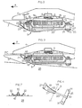
- - La figure 1 représente une vue de dessus de la barre de coupe d'une faucheuse à disques, équipée d'un exemple de réalisation d'un dispositif de décrottage selon l'invention,
- - La figure 2 représente une vue latérale en coupe de la barre de coupe de la figure 1 qui ne repose pas sur le sol, suivant le plan vertical V-V défini sur ladite figure 1,
- - La figure 3 représente une vue latérale en coupe de la barre de coupe de la figure 1 qui repose sur le sol (position de travail), suivant le plan vertical V-V défini sur ladite figure 1,
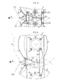
- - La figure 4 représente une vue en perspective du dispositif de décrottage démonté qui équipe la barre de coupe des figures 1, 2 et 3,
- - La figure 5 représente une vue de dessous de la barre de coupe équipée d'un carter vissé et montre le mode de montage du dispositif de décrottage sur ledit carter vissé,
- - La figure 6 représente une vue de dessous de la barre de coupe équipée d'un carter soudé et montre le mode de montage d'une variante de réalisation du dispositif de décrottage sur ledit carter soudé,
- - La figure 7 représente une section du dispositif de décrottage suivant la ligne VII-VII de la figure 4.
- FIG. 1 represents a top view of the cutter bar of a disc mower, equipped with an exemplary embodiment of a striker device according to the invention,
- FIG. 2 represents a side view in section of the cutter bar of FIG. 1 which does not rest on the ground, along the vertical plane VV defined in said FIG. 1,
- FIG. 3 represents a side view in section of the cutter bar of FIG. 1 which rests on the ground (working position), along the vertical plane VV defined in said FIG. 1,
- FIG. 4 represents a perspective view of the disassembled stripping device which equips the cutter bar of FIGS. 1, 2 and 3,
- FIG. 5 represents a bottom view of the cutter bar equipped with a screwed casing and shows the method of mounting the stripping device on said screwed casing,
- - Figure 6 shows a bottom view of the cutter bar equipped with a welded housing and shows the mounting method of an alternative embodiment of the device stripping on said welded casing,
- FIG. 7 represents a section of the stripping device along line VII-VII of FIG. 4.
Sur la figure 1, on voit la barre de coupe d'une faucheuse à disques. Cette barre de coupe comprend un carter (1) dans lequel est logée une série de roues dentées (2) entraînées en rotation à partir de la prise de force d'un tracteur non représenté, par un mécanisme (3) connu tel que carter de renvoi, poulies et courroies par exemple. Les roues dentées (2) entraînent en rotation des disques (4) munis chacun de deux couteaux (5) diamétralement opposés pouvant tourner librement autour d'axes (6) aménagés dans les disques (4). Les couteaux (5) sont maintenus dans leur position de travail sous l'effet de la force centrifuge et décrivent de ce fait des trajectoires circulaires (T) lorsque les disques (4) sont entraînés en rotation. A l'avant du carter (1) vu dans le sens d'avancement (A) de la faucheuse, s'étendent, sensiblement sous chaque disque (4), des secteurs circulaires (7) qui ont un rayon légèrement plus grand que le rayon des trajectoires (T') des disques (4) mais plus petit que le rayon des trajectoires (T) des couteaux (5). De ce fait, les disques (4) sont protégés contre tout obstacle qui se trouve sur le sol sur lequel opère la faucheuse. Seuls les couteaux (5) ne sont pas protégés, mais comme ceux-ci sont montés librement tournant sur les disques (4), ils peuvent se ranger sous lesdits disques (4) lorsqu'ils heurtent un obstacle, puis reprendre leur position de travail dès que l'obstacle est franchi.In Figure 1, we see the cutter bar of a disc mower. This cutter bar comprises a housing (1) in which is housed a series of toothed wheels (2) driven in rotation from the power take-off of a tractor not shown, by a known mechanism (3) such as return, pulleys and belts for example. The toothed wheels (2) rotate discs (4) each provided with two diametrically opposed knives (5) which can rotate freely around axes (6) arranged in the discs (4). The knives (5) are held in their working position under the effect of centrifugal force and therefore describe circular paths (T) when the discs (4) are rotated. At the front of the casing (1) seen in the direction of advance (A) of the mower, extend, substantially under each disc (4), circular sectors (7) which have a radius slightly larger than the radius of the trajectories (T ') of the discs (4) but smaller than the radius of the trajectories (T) of the knives (5). Therefore, the discs (4) are protected against any obstacle which is on the ground on which the mower operates. Only the knives (5) are not protected, but as these are mounted freely rotating on the discs (4), they can be stored under said discs (4) when they strike an obstacle, then return to their working position as soon as the obstacle is crossed.
A l'avant du carter (1), entre le premier et le deuxième disque et entre le troisième et le quatrième disque, endroits où les couteaux (5) des disques (4) convergent pendant leur rotation vers le carter (1), sont aménagés des organes de protection (8) dont la fonction est de protéger le carter lors du choc dû à un couteau (5) éventuellement plié lors de l'interférence avec un obstacle.At the front of the casing (1), between the first and the second disc and between the third and the fourth disc, places where the knives (5) of the discs (4) converge during their rotation towards the casing (1), are fitted with protective members (8) whose function is to protect the casing during an impact due to a knife (5) possibly bent during interference with an obstacle.
Dans les zones situées entre deux disques (4) voisins s'étendent des dispositifs de décrottage (9) qui peuvent se déplacer sensiblement perpendiculairement par rapport au plan de la figure 1 et latéralement par rapport au sens d'avancement (A) de la faucheuse. Ce mouvement relatif par rapport au carter (1) empêche les accumulations de terre qui peuvent se former en ces endroits et qui gênent le bon déroulement de l'opération de fauchage.In the areas between two neighboring disks (4) extend strippers (9) which can move substantially perpendicular to the plane of Figure 1 and laterally relative to the direction of advance (A) of the mower. This relative movement with respect to the casing (1) prevents accumulations of soil which may form in these places and which hinder the smooth running of the mowing operation.
Sur la figure 2, on voit que le carter (1) de la barre de coupe est formé par deux tôles pliées (10, 11) assemblées entre elles par des vis et écrous (12, 13, 14, 15) qui traversent leurs bords extérieurs, de manière à former un espace intérieur dans lequel sont logées les roues dentées (2). Il est également possible que le carter (1) soit formé par'une seule tôle pliée et une tôle plate assemblées entre elles d'une manière identique à celle décrite ci-dessus. Sur la tôle supérieure (10) du carter (1) sont fixés à l'aide de vis (16) des paliers de disques (17) dans lesquels sont guidés en rotation les axes non représentés des disques (4). A la partie frontale (18) du carter (1) s'étendent les organes de protection (8) et les secteurs circulaires (7). Sous la tôle inférieure (11), le carter (1) est muni de dispositifs de décrottage (9) dont la partie avant est formée par une plaque (19) en forme de ski, de manière à ce qu'elle puisse facilement glisser sur le sol, reliée au carter (1) par l'intermédiaire d'une tige flexible (20) en acier à ressort qui permet à la plaque (19) de se déplacer au moins dans un sens sensiblement vertical et dans un sens transversal par rapport à l'avancement (A) de la faucheuse. La plaque (19) est encore susceptible de tourner légèrement autour de l'axe longitudinal de la tige flexible (20) qui possède avantageusement une section ronde.In Figure 2, we see that the housing (1) of the cutter bar is formed by two folded sheets (10, 11) assembled together by screws and nuts (12, 13, 14, 15) which pass through their edges exterior, so as to form an interior space in which the gear wheels (2) are housed. It is also possible that the casing (1) is formed by a single folded sheet and a flat sheet assembled together in a manner identical to that described above. On the upper sheet (10) of the casing (1) are fixed with screws (16) disc bearings (17) in which the axes (not shown) of the discs (4) are guided in rotation. At the front part (18) of the casing (1) extend the protective members (8) and the circular sectors (7). Under the lower sheet (11), the casing (1) is provided with strippers (9), the front part of which is formed by a ski-shaped plate (19), so that it can easily slide over the ground, connected to the casing (1) by means of a flexible rod (20) made of spring steel which allows the plate (19) to move at least in a substantially vertical direction and in a transverse direction with respect to at the advancement (A) of the mower. The plate (19) is also capable of turning slightly around the longitudinal axis of the flexible rod (20) which advantageously has a round section.
Le bord frontal (21) de la plaque (19) comporte une partie sensiblement horizontale (22), laquelle se termine par une partie dirigée vers le bas (23) qui s'étend avantageusement jusqu'à la plaque (19) et est avantageusement fixée à celle-ci par des moyens de fixation connus tels que brasage par exemple. Avec une telle forme, le bord frontal (21) de la plaque (19) est correctement renforcé de manière simple et facilement réalisable, contre les chocs qu'il est appelé à encaisser lors du travail de la faucheuse. La partie arrière (24) de la tige flexible (20) est reliée à une bride (25) dont la forme sera mieux visible sur la figure 4 qui sera décrite ultérieurement. Cette bride (25) est vissée au bord arrière (26) du carter '(1) à l'aide d'au moins un ensemble vis-écrou (14, 15) après interposition d'au moins une entretoise (27) également traversée par la ou les vis (14). De ce fait, les vis (14) sont avantageusement plus longues que les vis (12). Dans la position de repos du dispositif de décrottage (9), il existe un certain jeu vertical (Jv) de même qu'un certain jeu (Ja) dans le sens d'avancement de la faucheuse entre le carter (1) et le dispositif de décrottage (9). Le diamètre de la section ronde de la tige flexible (20) est avantageusement compris environ entre 4 et 10 millimètres. Cette fourchette de valeurs dudit diamètre représente le meilleur compromis entre résistance mécanique de la tige flexible (20) et insensibilité aux bourrages. Par insensibilité de la tige flexible (20) aux bourrages, il faut entendre que si une accumulation de terre se produit entre le carter (1) et ladite tige flexible (20), cette dernière pourra aisément, du fait de son diamètre relativement réduit, s'enfoncer dans ladite accumulation de terre, de sorte que le mouvement sensiblement vertical du dispositif de décrottage (9) n'est pas bloqué.The front edge (21) of the plate (19) has a substantially horizontal part (22), which ends in a downwardly directed part (23) which advantageously extends to the plate (19) and is advantageous ment fixed thereto by known fixing means such as soldering for example. With such a shape, the front edge (21) of the plate (19) is correctly reinforced in a simple and easily achievable manner, against the shocks that it is called upon to absorb during the work of the mower. The rear part (24) of the flexible rod (20) is connected to a flange (25) whose shape will be better visible in Figure 4 which will be described later. This flange (25) is screwed to the rear edge (26) of the casing '(1) using at least one screw-nut assembly (14, 15) after interposition of at least one spacer (27) also traversed by the screw (s) (14). As a result, the screws (14) are advantageously longer than the screws (12). In the rest position of the striker device (9), there is a certain vertical clearance (Jv) as well as a certain clearance (Ja) in the direction of advance of the mower between the casing (1) and the device stripping (9). The diameter of the round section of the flexible rod (20) is advantageously between approximately 4 and 10 millimeters. This range of values of said diameter represents the best compromise between mechanical resistance of the flexible rod (20) and insensitivity to blockages. By insensitivity of the flexible rod (20) to blockages, it should be understood that if an accumulation of soil occurs between the casing (1) and said flexible rod (20), the latter can easily, due to its relatively small diameter, sinking into said accumulation of soil, so that the substantially vertical movement of the striker (9) is not blocked.
Sur la figure 3, la barre de coupe repose sur le sol (28) par l'intermédiaire de secteurs circulaires (7) qui se prolongent sous le carter (1) en formant des patins non représentés. Pendant le travail, la barre de coupe possède un certain piquage vers l'avant pour que les couteaux (5) puissent couper le fourrage relativement près du sol. Lorsque la barre de coupe repose sur un sol plat, il est avantageux que la tige flexible (20) soit déformée d'une certaine valeur vers le haut pour que le dispositif de décrottage (9) repose avec une certaine pression initiale sur le sol (28).In FIG. 3, the cutter bar rests on the ground (28) by means of circular sectors (7) which extend under the casing (1) by forming pads which are not shown. During work, the cutter bar has some forward stitching so that the knives (5) can cut the forage relatively close to the ground. When the cutter bar rests on flat ground, it is advantageous for the flexible rod (20) to be deformed by a certain amount upwards so that the striker (9) rests with a certain initial pressure on the ground ( 28).
Lorsque la faucheuse est mise en mouvement dans le sens de la flèche (A), les vibrations engendrées principalement par la rotation des disques (4), font vibrer avec une certaine amplitude le dispositif de décrottage (9) suivant ses différents degrés de liberté. Lorsqu'une protubérance (29) se présente à l'endroit où glisse la plaque (19), celle-ci sera contrainte à se déplacer vers le haut et/ou à droite ou à gauche selon que ladite protubérance (29) touche la plaque (19) à droite ou à gauche. Si une accumulation de terre s'est formée à la partie frontale (18) du carter (1), celle-ci est soulevée et peut arriver dans la zone d'action des couteaux (5), c'est-à-dire au-dessus du plan de coupe (PC) de telle sorte que les couteaux (5) peuvent frapper cette accumulation et la disloquer en l'éparpillant derrière le carter (1). Si l'accumulation de terre n'arrive pas jusqu'au plan de coupe (PC), ce sont les vibrations dont est animée la plaque (19) qui peuvent décoller ladite accumulation du bord frontal (21) de ladite plaque (19). Le mouvement transversal dont est animée la plaque (19) quand elle rencontre une protubérance (29) est très avantageux dans la mesure où la terre qui arrive à se loger dans l'espace situé entre la plaque (19) et le carter (1) sensiblement à l'endroit où on voit l'écrou (13), est à nouveau forcée de se dégager latéralement. Cette action de dégagement latéral de la terre est amplifiée grâce à l'action de poussée que peut exercer la partie frontale de la tige flexible (20) lors de son déplacement latéral avec la plaque (19) sur laquelle elle est fixée. Il est évident, du fait que la plaque (19) repose avec une certaine pression initiale sur le sol (28), que lorsque ladite plaque (19) passe au-dessus d'un trou, elle se déplace vers le bas et éventuellement transversalement par rapport au sens (A), ce qui contribue également au décollage des accumulations à la partie frontale (18) du carter (1) et au dégagement latéral de la terre logée entre le carter (1) et la plaque (19). Par ailleurs, lorsque les moyens de suspension tels que la tige flexible (20) autorisent une légère rotation autour d'un axe dirigé sensiblement dans le sens d'avancement de la faucheuse, ce mouvement contribue également avantageusement au décollage des accumulations de terre.When the mower is set in movement in the direction of the arrow (A), the vibrations generated mainly by the rotation of the discs (4), vibrate with a certain amplitude the striker (9) according to its different degrees of freedom. When a protuberance (29) is present at the place where the plate slides (19), the latter will be forced to move upwards and / or to the right or to the left depending on whether said protuberance (29) touches the plate (19) right or left. If an accumulation of soil has formed on the front part (18) of the housing (1), it is raised and can reach the area of action of the knives (5), that is to say at the - above the cutting plane (PC) so that the knives (5) can strike this accumulation and dislocate it by scattering it behind the casing (1). If the accumulation of soil does not reach the cutting plane (PC), it is the vibrations which animates the plate (19) which can detach said accumulation from the front edge (21) of said plate (19). The transverse movement which animates the plate (19) when it encounters a protuberance (29) is very advantageous insofar as the earth which gets to lodge in the space situated between the plate (19) and the casing (1) substantially where we see the nut (13), is again forced to disengage laterally. This lateral release action of the earth is amplified by the pushing action which the front part of the flexible rod (20) can exert during its lateral displacement with the plate (19) on which it is fixed. It is obvious, from the fact that the plate (19) rests with a certain initial pressure on the ground (28), that when said plate (19) passes over a hole, it becomes moves downward and possibly transversely with respect to the direction (A), which also contributes to the removal of accumulations from the front part (18) of the casing (1) and to the lateral clearance of the earth housed between the casing (1) and the plate (19). Furthermore, when the suspension means such as the flexible rod (20) allow a slight rotation about an axis directed substantially in the direction of advance of the mower, this movement also advantageously contributes to the takeoff of accumulations of soil.
En effet, lorsque la plaque (19) tourne autour d'un axe sensiblement dirigé dans le sens d'avancement (A), le bord de la plaque (19) qui est en contact avec le sol, permet de décoller l'accumulation de terre le long de la ligne de jonction de ladite accumulation avec un des secteurs circulaires (7).Indeed, when the plate (19) rotates about an axis substantially directed in the direction of advance (A), the edge of the plate (19) which is in contact with the ground, makes it possible to take off the accumulation of earth along the junction line of said accumulation with one of the circular sectors (7).
Sur la figure 3, on voit également que le déplacement vers le haut de la plaque (19) est limité. Cette limitation est par exemple réalisée dans le cas de la figure 3, par la partie frontale de la tige flexible (20) qui bute contre le dessous du carter (1) mais peut être réalisée par d'autres moyens. Ainsi lorsque la plaque (19) rencontre une protubérance (29) trop haute, le bord frontal (21) de ladite plaque (19) reste toujours en dessous du plan de coupe (PC) et on ne risque donc aucune interférence avec les couteaux (5).In FIG. 3, it can also be seen that the upward movement of the plate (19) is limited. This limitation is for example made in the case of Figure 3, by the front part of the flexible rod (20) which abuts against the underside of the housing (1) but can be achieved by other means. Thus when the plate (19) encounters a protrusion (29) that is too high, the front edge (21) of said plate (19) always remains below the cutting plane (PC) and there is therefore no risk of interference with the knives ( 5).
Sur la figure 4, on voit de manière plus précise la forme de la bride (25). Celle-ci comporte dans sa partie centrale un décrochement sensiblement circulaire (30) dans lequel vient se loger l'extrémité arrière de la tige flexible (20) qui y est fixée par brasage par exemple.In Figure 4, we can see more precisely the shape of the flange (25). This comprises in its central part a substantially circular recess (30) in which is housed the rear end of the flexible rod (20) which is fixed therein by brazing for example.
Le dessus de la tige flexible (20) est sensiblement au niveau de la face supérieure de la bride (25) mais avantageusement légèrement plus haut que ladite face supérieure pour que, lors du serrage des vis et écrous (14, 15), le dessus de la tige flexible (20) soit bien pressé contre l'entretoise (27).The top of the flexible rod (20) is substantially at the level of the upper face of the flange (25) but advantageously slightly higher than said upper face so that, when tightening the screws and nuts (14, 15), the top flexible rod (20) is pressed firmly against the spacer (27).
On voit également que la bride (25) comporte deux trous (31) par lesquels passent les vis (14).It can also be seen that the flange (25) has two holes (31) through which the screws (14) pass.
De plus, les bords latéraux (32, 33) de la plaque (19) sensiblement dirigés dans le sens d'avancement (A) de la faucheuse, sont recourbés vers le haut tel que visible sur la figure 7. Ainsi, la plaque (19) peut mieux glisser sur les pierres qui se trouvent sur le sol (28).In addition, the lateral edges (32, 33) of the plate (19) substantially directed in the direction of advance (A) of the mower, are bent upwards as visible in FIG. 7. Thus, the plate ( 19) can slide better on the stones which are on the ground (28).
Sur la Figure 5, on voit le dessous du carter (1) et le montage du dispositif de décrottage (9) décrit plus haut. La dimension de la plaque (19) est telle que son bord frontal (21) ne s'étende pas au-delà du point d'intersection (P) des trajectoires extrêmes (T) que décrivent les couteaux (5) pendant leur rotation. Entre la partie sensiblement horizontale (22) de la plaque (19) et les deux secteurs circulaires (7), il existe de part et d'autre, un certain jeu latéral (Jl) de sorte que le mouvement transversal et éventuellement, si elle existe, la rotation autour d'un axe dirigé sensiblement dans le sens d'avancement (A), puissent se réaliser. La pratique a montré que le jeu latéral (Jl) peut être inférieur au jeu vertical (Jv), c'est-à-dire que l'amplitude du mouvement transversal peut être inférieure à celle du mouvement sensiblement vertical. Par ailleurs, les bords latéraux (32, 33) de la plaque (19) sont avantageusement convergents dans le sens contraire de la flèche (A), c'est-à-dire que la largeur de la plaque (19) diminue depuis son bord frontal (21) jusqu'à son bord arrière (34). Avec une telle forme on évite que la terre et les fines brindilles ce fourrage ne viennent se coller à la partie arrière des bords latéraux (32, 33) au voisinage du bord arrière (34). En effet, lorsque la plaque (19) passe sur une taupinière, elle va y creuser une tranchée dont la largeur est sensiblement égale à la largeur de son bord frontal (21) de telle sorte que les bords latéraux (32, 33) de ladite plaque (19) puissent passer dans cette tranchée sans toucher les bords de celle-ci, et la terre ne risque donc pas de se coller auxdits bords latéraux (32, 33).In Figure 5, we see the underside of the housing (1) and the mounting of the striker device (9) described above. The dimension of the plate (19) is such that its front edge (21) does not extend beyond the point of intersection (P) of the extreme trajectories (T) that the knives (5) describe during their rotation. Between the substantially horizontal part (22) of the plate (19) and the two circular sectors (7), there is on both sides, a certain lateral clearance (Jl) so that the transverse movement and possibly, if it exists, the rotation around an axis directed substantially in the direction of advance (A), can be achieved. Practice has shown that the lateral play (Jl) can be less than the vertical play (Jv), that is to say that the amplitude of the transverse movement can be lower than that of the substantially vertical movement. Furthermore, the lateral edges (32, 33) of the plate (19) are advantageously convergent in the opposite direction of the arrow (A), that is to say that the width of the plate (19) decreases from its front edge (21) to its rear edge (34). With such a shape, the soil and the fine twigs of this fodder are prevented from sticking to the rear part of the lateral edges (32, 33) in the vicinity of the rear edge (34). Indeed, when the plate (19) passes over a molehill, it will dig a trench therein whose width is substantially equal to the width of its front edge (21) so that the side edges (32, 33) of said plate (19) can pass through this trench without tou expensive the edges thereof, and the earth therefore does not risk sticking to said side edges (32, 33).
La figure 6 représente une variante de réalisation du dispositif de décrottage (9). Ce dispositif ne comporte plus de tige flexible (20) comme dans l'exemple précédent mais les moyens de suspension sont réalisés par la plaque (19) elle-même qui est formée de telle façon que sa partie arrière est constituée par un manche (35) de largeur sensiblement constante et qui est fixé à l'arrière sur une plaquette (36). Il est évident que la forme du manche (35) peut être quelconque. Sa section peut en particulier être sensiblement ronde et avoisiner celle de la tige flexible (20) de l'exemple précédent. La plaquette (36) comporte deux trous chacun traversé par l'une des vis (37) qui servent à fixer les paliers de disques (38) sur le carter soudé (1). La partie avant de la plaque (19) reste sensiblement identique à celle de l'exemple précédent. Cette plaque (19) pourra être rendue plus rigide. Pour ce faire, on pourra avantageusement la doter d'une nervure qui pourra s'étendre sensiblement le long de son axe longitudinal. Une telle nervure pourra être réalisée par emboutissage par exemple et au moins une partie de celle-ci pourra avoir une forme qui sera partiellement semblable à la forme du manche (35). Avantageusement, la nervure et le manche (35) pourront se raccorder l'un à l'autre. Ce mode de réalisation des moyens de suspension autorise à la plaque (19) principalement un mouvement sensiblement vertical et un mouvement de rotation autour d'un axe sensiblement dirigé dans le sens d'avancement (A) de la faucheuse. Ce mouvement de rotation empêchera entre autres l'accumulation de terre entre le carter (1) et la plaque (19).Figure 6 shows an alternative embodiment of the striker device (9). This device no longer comprises a flexible rod (20) as in the previous example but the suspension means are produced by the plate (19) itself which is formed in such a way that its rear part is constituted by a handle (35 ) of substantially constant width and which is fixed at the rear on a plate (36). It is obvious that the shape of the handle (35) can be arbitrary. Its section may in particular be substantially round and be close to that of the flexible rod (20) of the previous example. The plate (36) has two holes each traversed by one of the screws (37) which serve to fix the disc bearings (38) on the welded casing (1). The front part of the plate (19) remains substantially identical to that of the previous example. This plate (19) can be made more rigid. To do this, it can advantageously be provided with a rib which may extend substantially along its longitudinal axis. Such a rib may be produced by stamping, for example, and at least part of it may have a shape which will be partially similar to the shape of the handle (35). Advantageously, the rib and the handle (35) can be connected to one another. This embodiment of the suspension means allows the plate (19) mainly a substantially vertical movement and a rotational movement about an axis substantially directed in the direction of advance (A) of the mower. This rotational movement will prevent, among other things, the accumulation of soil between the casing (1) and the plate (19).
Claims (26)
Priority Applications (1)
| Application Number | Priority Date | Filing Date | Title |
|---|---|---|---|
| AT83440033T ATE48364T1 (en) | 1982-07-09 | 1983-06-15 | DEVICE FOR PREVENTING EARTH COLLECTION ON THE HOUSING OF A DISC MOWER. |
Applications Claiming Priority (2)
| Application Number | Priority Date | Filing Date | Title |
|---|---|---|---|
| FR8212234A FR2529744A1 (en) | 1982-07-09 | 1982-07-09 | DEVICE FOR DECROCING THE HOUSING OF A DISC MOWER |
| FR8212234 | 1982-07-09 |
Publications (3)
| Publication Number | Publication Date |
|---|---|
| EP0099314A2 true EP0099314A2 (en) | 1984-01-25 |
| EP0099314A3 EP0099314A3 (en) | 1985-04-10 |
| EP0099314B1 EP0099314B1 (en) | 1989-12-06 |
Family
ID=9275934
Family Applications (1)
| Application Number | Title | Priority Date | Filing Date |
|---|---|---|---|
| EP83440033A Expired EP0099314B1 (en) | 1982-07-09 | 1983-06-15 | Device preventing the accumulation of earth at a disc mower housing |
Country Status (6)
| Country | Link |
|---|---|
| US (1) | US4633656A (en) |
| EP (1) | EP0099314B1 (en) |
| AT (1) | ATE48364T1 (en) |
| DE (1) | DE3380921D1 (en) |
| DK (1) | DK313783A (en) |
| FR (1) | FR2529744A1 (en) |
Cited By (5)
| Publication number | Priority date | Publication date | Assignee | Title |
|---|---|---|---|---|
| FR2570248A1 (en) * | 1984-09-19 | 1986-03-21 | Kuhn Sa | ROTATING MOWER |
| FR2572881A1 (en) * | 1984-11-12 | 1986-05-16 | Kuhn Sa | MOWER COMPRISING A CHASSIS HAVING AN INTERMEDIATE STRUCTURE AND MEANS FOR PREVENTING FORAGE FITTING AT THE INTERMEDIATE STRUCTURE. |
| FR2636203A1 (en) * | 1988-09-13 | 1990-03-16 | Kuhn Sa | MOWER WITH IMPROVED SKATES |
| EP0407321A1 (en) * | 1989-07-07 | 1991-01-09 | Kuhn S.A. | Mowerconditioner with means intended to modify the current of air produced by the cutting means |
| EP2508062A1 (en) * | 2011-04-07 | 2012-10-10 | CLAAS Saulgau GmbH | Disc mower |
Families Citing this family (19)
| Publication number | Priority date | Publication date | Assignee | Title |
|---|---|---|---|---|
| NL8503156A (en) * | 1985-11-15 | 1987-06-01 | Zweegers & Zonen P J | CUTTING MACHINE. |
| US4815262A (en) * | 1986-03-31 | 1989-03-28 | Ford New Holland, Inc. | Disc cutterbar construction |
| US4729212A (en) * | 1986-09-18 | 1988-03-08 | Rabitsch Thermon D | Protective cover for combine skid plates |
| US5379578A (en) * | 1994-01-25 | 1995-01-10 | Agronomics, Inc. | Green sugar cane billetting combine |
| FR2724689B1 (en) * | 1994-09-16 | 1997-01-24 | Kuhn Sa | LOCKING MECHANISM FOR MAINLY EQUIPPING AN AGRICULTURAL MACHINE |
| FR2736505B1 (en) * | 1995-07-13 | 1997-09-26 | Kuhn Sa | MOWER WITH AN IMPROVED RAKING DEVICE |
| USD391582S (en) | 1996-09-25 | 1998-03-03 | May-Wes Manufacturing | Skid shoe |
| US5924270A (en) * | 1995-11-16 | 1999-07-20 | May-Wes Manufacturing, Inc. | Skid shoe |
| USD382570S (en) * | 1995-11-16 | 1997-08-19 | May-Wes Manufacturing, Inc. | Skid shoe |
| FR2743978B1 (en) * | 1996-01-31 | 1998-04-17 | Kuhn Sa | MOWER WITH IMPROVED REMOVAL MEMBER |
| USD446222S1 (en) | 2000-04-03 | 2001-08-07 | Mark W. Bruns | Skid shoe |
| DE10224669A1 (en) * | 2002-06-03 | 2003-12-11 | Claas Saulgau Gmbh | Scheibenmähwerk |
| FR2882890B1 (en) * | 2005-03-08 | 2007-05-18 | Kuhn Sa Sa | METHOD OF MAKING A CUTTING BAR CASTER OF A DISC MOWER AND CASE OBTAINED |
| BR102013019208A2 (en) * | 2013-07-29 | 2015-11-10 | Marchesan Implementos E Máquinas Agrícolas Tatú S A | cutter and base cutter set |
| DE102014009158B4 (en) * | 2014-06-25 | 2023-01-26 | Carl Geringhoff Gmbh & Co. Kg | Cutting unit with support wheels |
| US9861036B2 (en) * | 2014-07-15 | 2018-01-09 | Cnh Industrial America Llc | Skid shoe for a header of an agricultural harvester |
| DE102015214051A1 (en) * | 2015-07-24 | 2017-01-26 | Deere & Company | Knife rotor for a mowing device Clamping tool and mowing device with such |
| FR3052016B1 (en) * | 2016-06-01 | 2018-06-15 | Kuhn S.A. | ROTATING DISC CUTTING MOWER WITH KNIFE |
| FR3058024B1 (en) * | 2016-10-28 | 2019-06-07 | Kuhn Sa | AGRICULTURAL MACHINE WITH SKATES EQUIPPED WITH INTERCHANGEABLE LINERS |
Family Cites Families (12)
| Publication number | Priority date | Publication date | Assignee | Title |
|---|---|---|---|---|
| US2267944A (en) * | 1938-07-28 | 1941-12-30 | William C Osterholm | Cutting machine |
| US2532174A (en) * | 1946-10-25 | 1950-11-28 | Edgar M Lieberman | Mower |
| NL6506452A (en) * | 1965-05-20 | 1966-11-21 | ||
| US3513648A (en) * | 1967-05-25 | 1970-05-26 | Sperry Rand Corp | Rotary mower disc guards |
| DE2104512A1 (en) * | 1970-02-02 | 1971-08-19 | Dronningborg Maskinfabrik A/S, Randers (Dänemark) | Mower harvester |
| GB1515268A (en) * | 1974-04-24 | 1978-06-21 | Clayson Nv | Rotary mowers |
| NL7513925A (en) * | 1975-11-28 | 1977-06-01 | Multinorm Bv | MOWING DEVICE. |
| FR2377755A1 (en) * | 1977-01-19 | 1978-08-18 | Vicon Nv | MOWER, LAWN MOWER OR SIMILAR MACHINE |
| GB2002622B (en) * | 1977-08-18 | 1982-01-20 | Sperry Rand Ltd | Disc mowers |
| NL7801408A (en) * | 1978-02-07 | 1979-08-09 | Vicon Nv | MOWING DEVICE. |
| FR2496391A1 (en) * | 1980-12-19 | 1982-06-25 | Kuhn Sa | IMPROVEMENT TO MOWER |
| DE3151770A1 (en) * | 1981-12-29 | 1983-07-07 | Paul E. 8004 Zürich Müller | "DEVICE FOR PREVENTING THE CLOGGING OR DEGRADING EARTH AND PLANT MEASURES ON A DISC MOWER" |
-
1982
- 1982-07-09 FR FR8212234A patent/FR2529744A1/en active Granted
-
1983
- 1983-06-15 EP EP83440033A patent/EP0099314B1/en not_active Expired
- 1983-06-15 DE DE8383440033T patent/DE3380921D1/en not_active Expired - Fee Related
- 1983-06-15 AT AT83440033T patent/ATE48364T1/en not_active IP Right Cessation
- 1983-07-07 DK DK313783A patent/DK313783A/en not_active Application Discontinuation
-
1986
- 1986-01-15 US US06/820,574 patent/US4633656A/en not_active Expired - Fee Related
Cited By (12)
| Publication number | Priority date | Publication date | Assignee | Title |
|---|---|---|---|---|
| FR2570248A1 (en) * | 1984-09-19 | 1986-03-21 | Kuhn Sa | ROTATING MOWER |
| EP0175629A1 (en) * | 1984-09-19 | 1986-03-26 | Kuhn S.A. | Rotary mower |
| EP0297384A3 (en) * | 1984-09-19 | 1990-10-10 | Kuhn S.A. | Rotary mower |
| FR2572881A1 (en) * | 1984-11-12 | 1986-05-16 | Kuhn Sa | MOWER COMPRISING A CHASSIS HAVING AN INTERMEDIATE STRUCTURE AND MEANS FOR PREVENTING FORAGE FITTING AT THE INTERMEDIATE STRUCTURE. |
| EP0184533A1 (en) * | 1984-11-12 | 1986-06-11 | Kuhn S.A. | Mowing machine with an intermediate structure and means to prevent the accumulation of crop material |
| US4694640A (en) * | 1984-11-12 | 1987-09-22 | Kuhn S.A. | Mowing machine for cutting hay and cereal grass |
| FR2636203A1 (en) * | 1988-09-13 | 1990-03-16 | Kuhn Sa | MOWER WITH IMPROVED SKATES |
| EP0360716A1 (en) * | 1988-09-13 | 1990-03-28 | Kuhn S.A. | Mower with improved skids |
| US4986061A (en) * | 1988-09-13 | 1991-01-22 | Kuhn, S.A. | Mower with skids |
| EP0407321A1 (en) * | 1989-07-07 | 1991-01-09 | Kuhn S.A. | Mowerconditioner with means intended to modify the current of air produced by the cutting means |
| FR2649283A1 (en) * | 1989-07-07 | 1991-01-11 | Kuhn Sa | MOWER-CONDITIONER HAVING MECHANISMS FOR MODIFYING THE FLOW OF AIR CAUSED BY CUTTING BODIES |
| EP2508062A1 (en) * | 2011-04-07 | 2012-10-10 | CLAAS Saulgau GmbH | Disc mower |
Also Published As
| Publication number | Publication date |
|---|---|
| EP0099314B1 (en) | 1989-12-06 |
| DK313783D0 (en) | 1983-07-07 |
| DE3380921D1 (en) | 1990-01-11 |
| EP0099314A3 (en) | 1985-04-10 |
| US4633656A (en) | 1987-01-06 |
| DK313783A (en) | 1984-01-10 |
| FR2529744B1 (en) | 1985-02-22 |
| FR2529744A1 (en) | 1984-01-13 |
| ATE48364T1 (en) | 1989-12-15 |
Similar Documents
| Publication | Publication Date | Title |
|---|---|---|
| EP0099314B1 (en) | Device preventing the accumulation of earth at a disc mower housing | |
| EP0408088B1 (en) | Rotary mower | |
| CA1335865C (en) | Harvesting machines | |
| EP0245186B1 (en) | Mowing device | |
| EP0337909B1 (en) | Mower with direct drive | |
| EP0175629B1 (en) | Rotary mower | |
| EP1125487B1 (en) | Multipurpose machine for intercultivation of tree or bush plantations such as vineyards or orchards | |
| EP0322327B1 (en) | A mower with improved stiffening of the cutting bar | |
| EP0206965A1 (en) | Rotary mower | |
| FR2590441A2 (en) | PERFECTED MOWER | |
| FR2549685A1 (en) | HARVESTING DEVICE FOR GRASSES, SUCH AS MAIZE, ARRANGED | |
| WO1993023988A1 (en) | Machine for the destruction of banana plantation | |
| EP3935934B1 (en) | Agricultural device with a cutter bar and a removable collecting device and agricultural machine comprising such a device | |
| EP1190616B1 (en) | Mulching mower | |
| EP2923539A1 (en) | Seed drill with built-in roller for destroying plant cover | |
| EP0603086B1 (en) | Blade for machines like portable brush cutters and lawn mowers | |
| FR2630289A1 (en) | Mowing unit whose cutting tools are connected to their cutting member by a linkage device using a spindle and leaf spring, and mowing machine using such a mowing unit | |
| FR2553965A1 (en) | Mower with vertical rotors | |
| FR2733115A1 (en) | Rotary cutter for vegetation, | |
| EP0135459A1 (en) | Disc mower | |
| EP0756814A1 (en) | Brushmower housing | |
| FR2923135A1 (en) | LAMIER AT BATI CURVILIGNE | |
| FR2584564A1 (en) | Rotary mower | |
| FR2644972A1 (en) | Stalk shredder for a maize picker | |
| FR2533800A1 (en) | Mechanical reaper |
Legal Events
| Date | Code | Title | Description |
|---|---|---|---|
| PUAI | Public reference made under article 153(3) epc to a published international application that has entered the european phase |
Free format text: ORIGINAL CODE: 0009012 |
|
| AK | Designated contracting states |
Designated state(s): AT DE GB IT NL |
|
| 17P | Request for examination filed |
Effective date: 19840627 |
|
| PUAL | Search report despatched |
Free format text: ORIGINAL CODE: 0009013 |
|
| AK | Designated contracting states |
Designated state(s): AT DE GB IT NL |
|
| 17Q | First examination report despatched |
Effective date: 19861030 |
|
| GRAA | (expected) grant |
Free format text: ORIGINAL CODE: 0009210 |
|
| AK | Designated contracting states |
Kind code of ref document: B1 Designated state(s): AT DE GB IT NL |
|
| REF | Corresponds to: |
Ref document number: 48364 Country of ref document: AT Date of ref document: 19891215 Kind code of ref document: T |
|
| REF | Corresponds to: |
Ref document number: 3380921 Country of ref document: DE Date of ref document: 19900111 |
|
| ITF | It: translation for a ep patent filed | ||
| GBT | Gb: translation of ep patent filed (gb section 77(6)(a)/1977) | ||
| PLBE | No opposition filed within time limit |
Free format text: ORIGINAL CODE: 0009261 |
|
| STAA | Information on the status of an ep patent application or granted ep patent |
Free format text: STATUS: NO OPPOSITION FILED WITHIN TIME LIMIT |
|
| 26N | No opposition filed | ||
| PGFP | Annual fee paid to national office [announced via postgrant information from national office to epo] |
Ref country code: GB Payment date: 19910606 Year of fee payment: 9 |
|
| PGFP | Annual fee paid to national office [announced via postgrant information from national office to epo] |
Ref country code: AT Payment date: 19910627 Year of fee payment: 9 |
|
| ITTA | It: last paid annual fee | ||
| PGFP | Annual fee paid to national office [announced via postgrant information from national office to epo] |
Ref country code: DE Payment date: 19910708 Year of fee payment: 9 |
|
| PG25 | Lapsed in a contracting state [announced via postgrant information from national office to epo] |
Ref country code: GB Effective date: 19920615 Ref country code: AT Effective date: 19920615 |
|
| PGFP | Annual fee paid to national office [announced via postgrant information from national office to epo] |
Ref country code: NL Payment date: 19920630 Year of fee payment: 10 |
|
| GBPC | Gb: european patent ceased through non-payment of renewal fee |
Effective date: 19920615 |
|
| PG25 | Lapsed in a contracting state [announced via postgrant information from national office to epo] |
Ref country code: DE Effective date: 19930302 |
|
| PG25 | Lapsed in a contracting state [announced via postgrant information from national office to epo] |
Ref country code: NL Effective date: 19940101 |
|
| NLV4 | Nl: lapsed or anulled due to non-payment of the annual fee |