EP0099314A2 - Vorrichtung zum Verhindern von Erdanhäufung am Gehäuse eines Scheibenmähers - Google Patents
Vorrichtung zum Verhindern von Erdanhäufung am Gehäuse eines Scheibenmähers Download PDFInfo
- Publication number
- EP0099314A2 EP0099314A2 EP83440033A EP83440033A EP0099314A2 EP 0099314 A2 EP0099314 A2 EP 0099314A2 EP 83440033 A EP83440033 A EP 83440033A EP 83440033 A EP83440033 A EP 83440033A EP 0099314 A2 EP0099314 A2 EP 0099314A2
- Authority
- EP
- European Patent Office
- Prior art keywords
- housing
- plate
- casing
- mower
- suspension means
- Prior art date
- Legal status (The legal status is an assumption and is not a legal conclusion. Google has not performed a legal analysis and makes no representation as to the accuracy of the status listed.)
- Granted
Links
- 238000009825 accumulation Methods 0.000 title claims abstract description 24
- 239000002689 soil Substances 0.000 claims abstract description 25
- 239000000725 suspension Substances 0.000 claims abstract description 16
- 229910000639 Spring steel Inorganic materials 0.000 claims description 2
- 230000007423 decrease Effects 0.000 claims description 2
- 238000005476 soldering Methods 0.000 claims description 2
- 230000005540 biological transmission Effects 0.000 claims 1
- 238000003466 welding Methods 0.000 claims 1
- 238000006073 displacement reaction Methods 0.000 abstract description 7
- 230000035508 accumulation Effects 0.000 description 20
- 239000004459 forage Substances 0.000 description 4
- 238000000034 method Methods 0.000 description 2
- 230000001681 protective effect Effects 0.000 description 2
- 125000006850 spacer group Chemical group 0.000 description 2
- 238000005219 brazing Methods 0.000 description 1
- 230000001627 detrimental effect Effects 0.000 description 1
- 230000000694 effects Effects 0.000 description 1
- 238000003306 harvesting Methods 0.000 description 1
- 239000000203 mixture Substances 0.000 description 1
- 210000000056 organ Anatomy 0.000 description 1
- 238000007790 scraping Methods 0.000 description 1
- 230000035939 shock Effects 0.000 description 1
Images

Classifications
-
- A—HUMAN NECESSITIES
- A01—AGRICULTURE; FORESTRY; ANIMAL HUSBANDRY; HUNTING; TRAPPING; FISHING
- A01D—HARVESTING; MOWING
- A01D34/00—Mowers; Mowing apparatus of harvesters
- A01D34/01—Mowers; Mowing apparatus of harvesters characterised by features relating to the type of cutting apparatus
- A01D34/412—Mowers; Mowing apparatus of harvesters characterised by features relating to the type of cutting apparatus having rotating cutters
- A01D34/63—Mowers; Mowing apparatus of harvesters characterised by features relating to the type of cutting apparatus having rotating cutters having cutters rotating about a vertical axis
- A01D34/64—Mowers; Mowing apparatus of harvesters characterised by features relating to the type of cutting apparatus having rotating cutters having cutters rotating about a vertical axis mounted on a vehicle, e.g. a tractor, or drawn by an animal or a vehicle
- A01D34/66—Mowers; Mowing apparatus of harvesters characterised by features relating to the type of cutting apparatus having rotating cutters having cutters rotating about a vertical axis mounted on a vehicle, e.g. a tractor, or drawn by an animal or a vehicle with two or more cutters
- A01D34/664—Disc cutter bars
Definitions
- the present invention relates to a device which prevents accumulations of soil in the housing of a disc mower in which are housed movement transmitting members for the drive from below of at least one of the discs located above. of said housing and each provided with at least one cutting tool, said device extending to the front part of the housing in an area located between two neighboring disks.
- the great disadvantage of a disc mower is that in wet ground or in which the earth is relatively sticky there occurs at the front part of the casing thereof and in particular at the places located between two neighboring discs, accumulations made up of a mixture of soil and fine twigs of cut fodder. If these accumulations extend forwards beyond the point of intersection of the extreme trajectories of the cutting tools, the latter can no longer cut the forage which is present in these places so that it remains in the field. streaks of uncut fodder which, if numerous, represents a significant loss of fodder. To reduce these losses and avoid total jamming of the cutter bar, it will therefore be necessary to stop frequently enough to remove the said accumulations, which considerably slows down the work.
- a disc mower which comprises, at the front part of the casing between two neighboring discs, scrapers which have the function of scraping the soil stuck to the knives.
- these scrapers have an inclined plane directed towards the ground along which the soil detached from the knives must slide without adhering to it.
- practice has shown that if these scrapers slow down the accumulation of soil, they cannot prevent them.
- the present invention overcomes this drawback insofar as the device preventing accumulations of soil in the housing of a mower as described in the introduction comprises suspension means allowing it to have at least two degrees of freedom by report to the housing.
- the suspension means thereof allow it to have elastically at least two degrees of freedom relative to the casing.
- This preferred embodiment of the invention makes it possible to substantially increase the stripping power of said device because as soon as the stripping device is removed from its normal position, the suspension means store a certain amount of energy that they are capable of. to restore as soon as the obstacle is crossed.
- a forced displacement of said device in one direction automatically causes a forced displacement in the opposite direction as soon as the obstacle is crossed.
- the two degrees of freedom that the stripping device comprises and in particular its front edge are respectively a substantially vertical movement and a transverse movement relative to the direction of advance of the machine.
- the front part of the casing is provided with means which protect the discs, there must be a certain lateral clearance between the striker and said means, so that the transverse movement can take place.
- the amplitude of the transverse movement may be less than that of the substantially vertical movement, which implies that the value of the lateral clearance to be provided for may be less than that of the vertical play.
- One of the great advantages of the transverse movement is to avoid that earth accumulates between the casing and the striker, and does not block the vertical movement of said device.
- the organs limit the substantially vertical movement of the striker device upwards so that, in the highest position, the striker device remains below the cutting plane. This prevents damage to said device by the cutting tools.
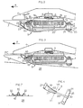
- FIG 1 we see the cutter bar of a disc mower.
- This cutter bar comprises a housing (1) in which is housed a series of toothed wheels (2) driven in rotation from the power take-off of a tractor not shown, by a known mechanism (3) such as return, pulleys and belts for example.
- the toothed wheels (2) rotate discs (4) each provided with two diametrically opposed knives (5) which can rotate freely around axes (6) arranged in the discs (4).
- the knives (5) are held in their working position under the effect of centrifugal force and therefore describe circular paths (T) when the discs (4) are rotated.
- strippers (9) which can move substantially perpendicular to the plane of Figure 1 and laterally relative to the direction of advance (A) of the mower. This relative movement with respect to the casing (1) prevents accumulations of soil which may form in these places and which hinder the smooth running of the mowing operation.
- the housing (1) of the cutter bar is formed by two folded sheets (10, 11) assembled together by screws and nuts (12, 13, 14, 15) which pass through their edges exterior, so as to form an interior space in which the gear wheels (2) are housed.
- the casing (1) is formed by a single folded sheet and a flat sheet assembled together in a manner identical to that described above.
- On the upper sheet (10) of the casing (1) are fixed with screws (16) disc bearings (17) in which the axes (not shown) of the discs (4) are guided in rotation.
- the protective members (8) and the circular sectors (7) At the front part (18) of the casing (1).
- the casing (1) is provided with strippers (9), the front part of which is formed by a ski-shaped plate (19), so that it can easily slide over the ground, connected to the casing (1) by means of a flexible rod (20) made of spring steel which allows the plate (19) to move at least in a substantially vertical direction and in a transverse direction with respect to at the advancement (A) of the mower.
- the plate (19) is also capable of turning slightly around the longitudinal axis of the flexible rod (20) which advantageously has a round section.
- the front edge (21) of the plate (19) has a substantially horizontal part (22), which ends in a downwardly directed part (23) which advantageously extends to the plate (19) and is advantageous ment fixed thereto by known fixing means such as soldering for example.
- the front edge (21) of the plate (19) is correctly reinforced in a simple and easily achievable manner, against the shocks that it is called upon to absorb during the work of the mower.
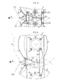
- the rear part (24) of the flexible rod (20) is connected to a flange (25) whose shape will be better visible in Figure 4 which will be described later.
- This flange (25) is screwed to the rear edge (26) of the casing '(1) using at least one screw-nut assembly (14, 15) after interposition of at least one spacer (27) also traversed by the screw (s) (14).
- the screws (14) are advantageously longer than the screws (12).
- the diameter of the round section of the flexible rod (20) is advantageously between approximately 4 and 10 millimeters. This range of values of said diameter represents the best compromise between mechanical resistance of the flexible rod (20) and insensitivity to blockages.
- the cutter bar rests on the ground (28) by means of circular sectors (7) which extend under the casing (1) by forming pads which are not shown.
- the cutter bar has some forward stitching so that the knives (5) can cut the forage relatively close to the ground.
- the flexible rod (20) it is advantageous for the flexible rod (20) to be deformed by a certain amount upwards so that the striker (9) rests with a certain initial pressure on the ground ( 28).
- the plate (19) rests with a certain initial pressure on the ground (28), that when said plate (19) passes over a hole, it becomes moves downward and possibly transversely with respect to the direction (A), which also contributes to the removal of accumulations from the front part (18) of the casing (1) and to the lateral clearance of the earth housed between the casing (1) and the plate (19).
- the suspension means such as the flexible rod (20) allow a slight rotation about an axis directed substantially in the direction of advance of the mower, this movement also advantageously contributes to the takeoff of accumulations of soil.
- FIG. 3 it can also be seen that the upward movement of the plate (19) is limited.
- This limitation is for example made in the case of Figure 3, by the front part of the flexible rod (20) which abuts against the underside of the housing (1) but can be achieved by other means.
- the plate (19) encounters a protrusion (29) that is too high, the front edge (21) of said plate (19) always remains below the cutting plane (PC) and there is therefore no risk of interference with the knives ( 5).
- the top of the flexible rod (20) is substantially at the level of the upper face of the flange (25) but advantageously slightly higher than said upper face so that, when tightening the screws and nuts (14, 15), the top flexible rod (20) is pressed firmly against the spacer (27).
- the flange (25) has two holes (31) through which the screws (14) pass.
- the plate ( 19) can slide better on the stones which are on the ground (28).
- the lateral edges (32, 33) of the plate (19) are advantageously convergent in the opposite direction of the arrow (A), that is to say that the width of the plate (19) decreases from its front edge (21) to its rear edge (34). With such a shape, the soil and the fine twigs of this fodder are prevented from sticking to the rear part of the lateral edges (32, 33) in the vicinity of the rear edge (34). Indeed, when the plate (19) passes over a molehill, it will dig a trench therein whose width is substantially equal to the width of its front edge (21) so that the side edges (32, 33) of said plate (19) can pass through this trench without tou expensive the edges thereof, and the earth therefore does not risk sticking to said side edges (32, 33).
- FIG 6 shows an alternative embodiment of the striker device (9).
- This device no longer comprises a flexible rod (20) as in the previous example but the suspension means are produced by the plate (19) itself which is formed in such a way that its rear part is constituted by a handle (35 ) of substantially constant width and which is fixed at the rear on a plate (36).
- the shape of the handle (35) can be arbitrary. Its section may in particular be substantially round and be close to that of the flexible rod (20) of the previous example.
- the plate (36) has two holes each traversed by one of the screws (37) which serve to fix the disc bearings (38) on the welded casing (1).
- the front part of the plate (19) remains substantially identical to that of the previous example.
- This plate (19) can be made more rigid.
- a rib which may extend substantially along its longitudinal axis.
- a rib may be produced by stamping, for example, and at least part of it may have a shape which will be partially similar to the shape of the handle (35).
- the rib and the handle (35) can be connected to one another.
- This embodiment of the suspension means allows the plate (19) mainly a substantially vertical movement and a rotational movement about an axis substantially directed in the direction of advance (A) of the mower. This rotational movement will prevent, among other things, the accumulation of soil between the casing (1) and the plate (19).
Landscapes
- Life Sciences & Earth Sciences (AREA)
- Environmental Sciences (AREA)
- Harvester Elements (AREA)
- Jib Cranes (AREA)
- Earth Drilling (AREA)
- Forklifts And Lifting Vehicles (AREA)
- Solid-Sorbent Or Filter-Aiding Compositions (AREA)
- Cold Cathode And The Manufacture (AREA)
- Sampling And Sample Adjustment (AREA)
Priority Applications (1)
| Application Number | Priority Date | Filing Date | Title |
|---|---|---|---|
| AT83440033T ATE48364T1 (de) | 1982-07-09 | 1983-06-15 | Vorrichtung zum verhindern von erdanhaeufung am gehaeuse eines scheibenmaehers. |
Applications Claiming Priority (2)
| Application Number | Priority Date | Filing Date | Title |
|---|---|---|---|
| FR8212234A FR2529744A1 (fr) | 1982-07-09 | 1982-07-09 | Dispositif de decrottage du carter d'une faucheuse a disques |
| FR8212234 | 1982-07-09 |
Publications (3)
| Publication Number | Publication Date |
|---|---|
| EP0099314A2 true EP0099314A2 (de) | 1984-01-25 |
| EP0099314A3 EP0099314A3 (en) | 1985-04-10 |
| EP0099314B1 EP0099314B1 (de) | 1989-12-06 |
Family
ID=9275934
Family Applications (1)
| Application Number | Title | Priority Date | Filing Date |
|---|---|---|---|
| EP83440033A Expired EP0099314B1 (de) | 1982-07-09 | 1983-06-15 | Vorrichtung zum Verhindern von Erdanhäufung am Gehäuse eines Scheibenmähers |
Country Status (6)
| Country | Link |
|---|---|
| US (1) | US4633656A (de) |
| EP (1) | EP0099314B1 (de) |
| AT (1) | ATE48364T1 (de) |
| DE (1) | DE3380921D1 (de) |
| DK (1) | DK313783A (de) |
| FR (1) | FR2529744A1 (de) |
Cited By (5)
| Publication number | Priority date | Publication date | Assignee | Title |
|---|---|---|---|---|
| FR2570248A1 (fr) * | 1984-09-19 | 1986-03-21 | Kuhn Sa | Faucheuse rotative |
| FR2572881A1 (fr) * | 1984-11-12 | 1986-05-16 | Kuhn Sa | Faucheuse comportant un chassis muni d'une structure intermediaire et de moyens destines a empecher l'accrochage de fourrage a la dite structure intermediaire. |
| FR2636203A1 (fr) * | 1988-09-13 | 1990-03-16 | Kuhn Sa | Faucheuse avec patins perfectionnes |
| EP0407321A1 (de) * | 1989-07-07 | 1991-01-09 | Kuhn S.A. | Mähconditioner mit Mitteln zum Ändern des von den Schneidorganen erzeugten Luftstroms |
| EP2508062A1 (de) * | 2011-04-07 | 2012-10-10 | CLAAS Saulgau GmbH | Scheibenmähwerk |
Families Citing this family (19)
| Publication number | Priority date | Publication date | Assignee | Title |
|---|---|---|---|---|
| NL8503156A (nl) * | 1985-11-15 | 1987-06-01 | Zweegers & Zonen P J | Maaiinrichting. |
| US4815262A (en) * | 1986-03-31 | 1989-03-28 | Ford New Holland, Inc. | Disc cutterbar construction |
| US4729212A (en) * | 1986-09-18 | 1988-03-08 | Rabitsch Thermon D | Protective cover for combine skid plates |
| US5379578A (en) * | 1994-01-25 | 1995-01-10 | Agronomics, Inc. | Green sugar cane billetting combine |
| FR2724689B1 (fr) * | 1994-09-16 | 1997-01-24 | Kuhn Sa | Mecanisme de verrouillage destine a equiper principalement une machine agricole |
| FR2736505B1 (fr) * | 1995-07-13 | 1997-09-26 | Kuhn Sa | Faucheuse avec un dispositif d'andainage perfectionne |
| USD391582S (en) | 1996-09-25 | 1998-03-03 | May-Wes Manufacturing | Skid shoe |
| US5924270A (en) * | 1995-11-16 | 1999-07-20 | May-Wes Manufacturing, Inc. | Skid shoe |
| USD382570S (en) * | 1995-11-16 | 1997-08-19 | May-Wes Manufacturing, Inc. | Skid shoe |
| FR2743978B1 (fr) * | 1996-01-31 | 1998-04-17 | Kuhn Sa | Faucheuse avec organe de depose perfectionne |
| USD446222S1 (en) | 2000-04-03 | 2001-08-07 | Mark W. Bruns | Skid shoe |
| DE10224669A1 (de) * | 2002-06-03 | 2003-12-11 | Claas Saulgau Gmbh | Scheibenmähwerk |
| FR2882890B1 (fr) * | 2005-03-08 | 2007-05-18 | Kuhn Sa Sa | Procede de realisation d'un carter de barre de coupe d'une faucheuse a disques et carter obtenu |
| BR102013019208A2 (pt) * | 2013-07-29 | 2015-11-10 | Marchesan Implementos E Máquinas Agrícolas Tatú S A | cortador e conjunto de corte de base |
| DE102014009158B4 (de) * | 2014-06-25 | 2023-01-26 | Carl Geringhoff Gmbh & Co. Kg | Schneidwerk mit Stützrädern |
| US9861036B2 (en) * | 2014-07-15 | 2018-01-09 | Cnh Industrial America Llc | Skid shoe for a header of an agricultural harvester |
| DE102015214051A1 (de) * | 2015-07-24 | 2017-01-26 | Deere & Company | Messerrotor für ein Mähgerät Spannwerkzeug und Mähgerät mit einem solchen |
| FR3052016B1 (fr) * | 2016-06-01 | 2018-06-15 | Kuhn S.A. | Faucheuse a barre de coupe a disques rotatifs a couteaux |
| FR3058024B1 (fr) * | 2016-10-28 | 2019-06-07 | Kuhn Sa | Machine agricole avec des patins equipes de doublures interchangeables |
Family Cites Families (12)
| Publication number | Priority date | Publication date | Assignee | Title |
|---|---|---|---|---|
| US2267944A (en) * | 1938-07-28 | 1941-12-30 | William C Osterholm | Cutting machine |
| US2532174A (en) * | 1946-10-25 | 1950-11-28 | Edgar M Lieberman | Mower |
| NL6506452A (de) * | 1965-05-20 | 1966-11-21 | ||
| US3513648A (en) * | 1967-05-25 | 1970-05-26 | Sperry Rand Corp | Rotary mower disc guards |
| DE2104512A1 (de) * | 1970-02-02 | 1971-08-19 | Dronningborg Maskinfabrik A/S, Randers (Dänemark) | Mäh- Erntemaschine |
| GB1515268A (en) * | 1974-04-24 | 1978-06-21 | Clayson Nv | Rotary mowers |
| NL7513925A (nl) * | 1975-11-28 | 1977-06-01 | Multinorm Bv | Maaiinrichting. |
| FR2377755A1 (fr) * | 1977-01-19 | 1978-08-18 | Vicon Nv | Faucheuse, tondeuse a gazon ou machine analogue |
| GB2002622B (en) * | 1977-08-18 | 1982-01-20 | Sperry Rand Ltd | Disc mowers |
| NL7801408A (nl) * | 1978-02-07 | 1979-08-09 | Vicon Nv | Maaiinrichting. |
| FR2496391A1 (fr) * | 1980-12-19 | 1982-06-25 | Kuhn Sa | Perfectionnement aux faucheuses |
| DE3151770A1 (de) * | 1981-12-29 | 1983-07-07 | Paul E. 8004 Zürich Müller | "vorrichtung zum verhueten des verstopfens bzw. zum abbauen von erd- und pflanzenmassen an einem scheibenmaeher" |
-
1982
- 1982-07-09 FR FR8212234A patent/FR2529744A1/fr active Granted
-
1983
- 1983-06-15 EP EP83440033A patent/EP0099314B1/de not_active Expired
- 1983-06-15 DE DE8383440033T patent/DE3380921D1/de not_active Expired - Fee Related
- 1983-06-15 AT AT83440033T patent/ATE48364T1/de not_active IP Right Cessation
- 1983-07-07 DK DK313783A patent/DK313783A/da not_active Application Discontinuation
-
1986
- 1986-01-15 US US06/820,574 patent/US4633656A/en not_active Expired - Fee Related
Cited By (12)
| Publication number | Priority date | Publication date | Assignee | Title |
|---|---|---|---|---|
| FR2570248A1 (fr) * | 1984-09-19 | 1986-03-21 | Kuhn Sa | Faucheuse rotative |
| EP0175629A1 (de) * | 1984-09-19 | 1986-03-26 | Kuhn S.A. | Kreiselmäher |
| EP0297384A3 (en) * | 1984-09-19 | 1990-10-10 | Kuhn S.A. | Rotary mower |
| FR2572881A1 (fr) * | 1984-11-12 | 1986-05-16 | Kuhn Sa | Faucheuse comportant un chassis muni d'une structure intermediaire et de moyens destines a empecher l'accrochage de fourrage a la dite structure intermediaire. |
| EP0184533A1 (de) * | 1984-11-12 | 1986-06-11 | Kuhn S.A. | Mähmaschine mit einer Zwischenstruktur und Mittel zum Verhüten eines Futterstaus |
| US4694640A (en) * | 1984-11-12 | 1987-09-22 | Kuhn S.A. | Mowing machine for cutting hay and cereal grass |
| FR2636203A1 (fr) * | 1988-09-13 | 1990-03-16 | Kuhn Sa | Faucheuse avec patins perfectionnes |
| EP0360716A1 (de) * | 1988-09-13 | 1990-03-28 | Kuhn S.A. | Mähwerk mit verbesserten Gleitkufen |
| US4986061A (en) * | 1988-09-13 | 1991-01-22 | Kuhn, S.A. | Mower with skids |
| EP0407321A1 (de) * | 1989-07-07 | 1991-01-09 | Kuhn S.A. | Mähconditioner mit Mitteln zum Ändern des von den Schneidorganen erzeugten Luftstroms |
| FR2649283A1 (fr) * | 1989-07-07 | 1991-01-11 | Kuhn Sa | Faucheuse-conditionneuse munie d'organes de modification du flux d'air engendre par les organes de coupe |
| EP2508062A1 (de) * | 2011-04-07 | 2012-10-10 | CLAAS Saulgau GmbH | Scheibenmähwerk |
Also Published As
| Publication number | Publication date |
|---|---|
| DK313783D0 (da) | 1983-07-07 |
| FR2529744A1 (fr) | 1984-01-13 |
| ATE48364T1 (de) | 1989-12-15 |
| DE3380921D1 (de) | 1990-01-11 |
| FR2529744B1 (de) | 1985-02-22 |
| US4633656A (en) | 1987-01-06 |
| EP0099314A3 (en) | 1985-04-10 |
| DK313783A (da) | 1984-01-10 |
| EP0099314B1 (de) | 1989-12-06 |
Similar Documents
| Publication | Publication Date | Title |
|---|---|---|
| EP0099314B1 (de) | Vorrichtung zum Verhindern von Erdanhäufung am Gehäuse eines Scheibenmähers | |
| EP0408088B1 (de) | Kreiselmäher | |
| CA1335865C (fr) | Machines agricoles pour la recolte | |
| EP0245186B1 (de) | Mähvorrichtung | |
| EP0337909B1 (de) | Direktangetriebene Mähmaschine | |
| EP0175629B1 (de) | Kreiselmäher | |
| EP1125487B1 (de) | Mehrzweckmaschine zum Zwischenkultivieren für Baum- oder Strauchpflanzungen bzw. Wein- oder Obstgärten | |
| EP0322327B1 (de) | Mähwerk mit versteiftem Mähbalken | |
| EP0206965A1 (de) | Rotationsmäher | |
| FR2590441A2 (fr) | Faucheuse perfectionnee | |
| FR2549685A1 (fr) | Dispositif de recolte pour graminees, telles que le mais, disposees en rangees | |
| WO1993023988A1 (fr) | Machine pour la destruction des dechets de bananeraie | |
| EP3935934B1 (de) | Landwirtschaftliches gerät mit einem mähbalken und einem abnehmbaren kollektor und landwirtschaftliche maschine mit einem solchen gerät | |
| EP1190616B1 (de) | Mulchmäher | |
| EP2923539A1 (de) | Sämaschine mit integrierter walze zum zerstören einer vegetationsdeckschicht | |
| EP0603086B1 (de) | Messer für Maschinen wie zum Beispiel tragbare Sichelmäher und Rasenmäher | |
| FR2630289A1 (fr) | Groupe faucheur dont les outils de coupe sont lies a leur organe de coupe par un dispositif de liaison a axe et ressort a lame et machine de fauchage utilisant un tel groupe faucheur | |
| FR2553965A1 (fr) | Faucheuse rotative | |
| FR2733115A1 (fr) | Dispositif debroussailleur-broyeur de vegetaux | |
| EP0135459A1 (de) | Scheibenmäher | |
| EP0756814A1 (de) | Buschmähergehäuse | |
| FR2923135A1 (fr) | Lamier a bati curviligne | |
| FR2584564A1 (fr) | Faucheuse | |
| FR2644972A1 (fr) | Broyeur de tiges pour cueilleur a mais | |
| FR2533800A1 (fr) | Faucheuse |
Legal Events
| Date | Code | Title | Description |
|---|---|---|---|
| PUAI | Public reference made under article 153(3) epc to a published international application that has entered the european phase |
Free format text: ORIGINAL CODE: 0009012 |
|
| AK | Designated contracting states |
Designated state(s): AT DE GB IT NL |
|
| 17P | Request for examination filed |
Effective date: 19840627 |
|
| PUAL | Search report despatched |
Free format text: ORIGINAL CODE: 0009013 |
|
| AK | Designated contracting states |
Designated state(s): AT DE GB IT NL |
|
| 17Q | First examination report despatched |
Effective date: 19861030 |
|
| GRAA | (expected) grant |
Free format text: ORIGINAL CODE: 0009210 |
|
| AK | Designated contracting states |
Kind code of ref document: B1 Designated state(s): AT DE GB IT NL |
|
| REF | Corresponds to: |
Ref document number: 48364 Country of ref document: AT Date of ref document: 19891215 Kind code of ref document: T |
|
| REF | Corresponds to: |
Ref document number: 3380921 Country of ref document: DE Date of ref document: 19900111 |
|
| ITF | It: translation for a ep patent filed | ||
| GBT | Gb: translation of ep patent filed (gb section 77(6)(a)/1977) | ||
| PLBE | No opposition filed within time limit |
Free format text: ORIGINAL CODE: 0009261 |
|
| STAA | Information on the status of an ep patent application or granted ep patent |
Free format text: STATUS: NO OPPOSITION FILED WITHIN TIME LIMIT |
|
| 26N | No opposition filed | ||
| PGFP | Annual fee paid to national office [announced via postgrant information from national office to epo] |
Ref country code: GB Payment date: 19910606 Year of fee payment: 9 |
|
| PGFP | Annual fee paid to national office [announced via postgrant information from national office to epo] |
Ref country code: AT Payment date: 19910627 Year of fee payment: 9 |
|
| ITTA | It: last paid annual fee | ||
| PGFP | Annual fee paid to national office [announced via postgrant information from national office to epo] |
Ref country code: DE Payment date: 19910708 Year of fee payment: 9 |
|
| PG25 | Lapsed in a contracting state [announced via postgrant information from national office to epo] |
Ref country code: GB Effective date: 19920615 Ref country code: AT Effective date: 19920615 |
|
| PGFP | Annual fee paid to national office [announced via postgrant information from national office to epo] |
Ref country code: NL Payment date: 19920630 Year of fee payment: 10 |
|
| GBPC | Gb: european patent ceased through non-payment of renewal fee |
Effective date: 19920615 |
|
| PG25 | Lapsed in a contracting state [announced via postgrant information from national office to epo] |
Ref country code: DE Effective date: 19930302 |
|
| PG25 | Lapsed in a contracting state [announced via postgrant information from national office to epo] |
Ref country code: NL Effective date: 19940101 |
|
| NLV4 | Nl: lapsed or anulled due to non-payment of the annual fee |