EP0099331A1 - Cuve cathodique pour cellule d'électrolyse d'aluminium - Google Patents
Cuve cathodique pour cellule d'électrolyse d'aluminium Download PDFInfo
- Publication number
- EP0099331A1 EP0099331A1 EP83810282A EP83810282A EP0099331A1 EP 0099331 A1 EP0099331 A1 EP 0099331A1 EP 83810282 A EP83810282 A EP 83810282A EP 83810282 A EP83810282 A EP 83810282A EP 0099331 A1 EP0099331 A1 EP 0099331A1
- Authority
- EP
- European Patent Office
- Prior art keywords
- carbon
- layer
- lining
- shear strength
- cathode
- Prior art date
- Legal status (The legal status is an assumption and is not a legal conclusion. Google has not performed a legal analysis and makes no representation as to the accuracy of the status listed.)
- Granted
Links
Images


Classifications
-
- C—CHEMISTRY; METALLURGY
- C25—ELECTROLYTIC OR ELECTROPHORETIC PROCESSES; APPARATUS THEREFOR
- C25C—PROCESSES FOR THE ELECTROLYTIC PRODUCTION, RECOVERY OR REFINING OF METALS; APPARATUS THEREFOR
- C25C3/00—Electrolytic production, recovery or refining of metals by electrolysis of melts
- C25C3/06—Electrolytic production, recovery or refining of metals by electrolysis of melts of aluminium
- C25C3/08—Cell construction, e.g. bottoms, walls, cathodes
Definitions
- the invention relates to a cathode tub of a melt flow electrolysis cell for the production of aluminum, consisting of an outer steel tub supported or supported by metal components, a heat-insulating layer and an electrically conductive inner lining made of carbon which is resistant to the molten aluminum and the electrolyte.
- the carbon lining experiences a significant increase in volume over the course of its operating life. This is caused by the penetration of components that come from the electrolyte.
- Components include, for example, sodium or salts from which the fluoride melt is composed, and chemical compounds, which have arisen from the fluoride melt by reactions which are not known in detail.
- the swelling carbon lining presses on the thermal insulation and thus indirectly on the steel tub. This can cause irreversible deformations that can strain them into the plastic area of the steel and cause them to tear.
- stiffeners represent a significant economic disadvantage, the cell becomes more expensive and the total weight of the cathode tub is increased considerably.
- DE-AS 26 33 055 it is proposed to form a bulge in the steel trough.
- This includes a storage space which is completely filled with a first, easily deformable material and a second material which can only be deformed with greater forces, in order to accommodate the bottom of the carbon lining, which expands in the horizontal direction during operation.
- the second material has such mechanical properties that the forces are transmitted to the bulged steel jacket without permanent deformation and / or cracking. The opposing forces acting on the bottom of the carbon lining reduce its bulging and cracking.
- the inventors have set themselves the task of creating a new concept for a cathode trough of a melt flow electrolysis cell for the production of aluminum, which can prevent uncontrolled deformations in cells of all sizes without causing damage to the cell in the form of cracking.
- the concept should continue to make do with low investment costs and be flexible to use.
- the object is achieved according to the invention by a layer which is arranged horizontally and exclusively in the area of the electrolyte and separates the carbon lining into a lower and an upper part from a material which is resistant to the electrolyte and is resistant to the electrolyte and has a significantly lower shear strength than that the carbon lining.
- the side wall of the carbon lining is divided.
- the electrical field between the cathode bars and the anodes passes through the bottom and lower part of the side wall of the carbon liner.
- practically no electrical current flows through the part of the side wall of the carbon lining that lies above the layer with low shear strength. Therefore, the lower part of the carbon lining swells much more than the upper part.
- the resulting tensions are absorbed by the layer with low shear strength tearing. Since it is completely in the Be molten electrolyte must be rich, no liquid aluminum can enter the cracks formed.
- the crack in the layer with low shear strength is self-healing; the molten electrolyte penetrating the crack cools so much in the outer area of the wall that it solidifies and thus prevents the electrolyte from flowing out.
- the self-healing of the predetermined breaking point can be improved by arranging a collecting zone made of very good heat-conducting material that extends in the direction of the side wall of the outer steel trough directly outside the layer with low shear strength and the area of the carbon lining adjoining it below. This means that the heat given off by the electrolyte entering the crack can be dissipated more quickly, and self-healing through solidification takes place more quickly.
- the upper limit of this collecting zone is expediently at approximately the same level as the upper limit of the layer with low shear strength. However, the collecting zone is thicker than this layer, it is advantageously two to three times as thick as the layer with low shear strength.
- Metallic materials, such as steel wool or aluminum chips, are particularly well suited for the rapid dissipation of heat in the collecting zone.
- the shear strength of the layer which is the carbon separates the material lining into a lower and upper part, preferably at least five times smaller than that of carbon.
- this layer with low shear strength is expediently between 2 and 15 cm, preferably between 5 and 10 cm.
- the layer separating the carbon lining into two parts is expediently built up from prefabricated blocks.
- the materials for these blocks must meet the three requirements of temperature resistance, resistance to the electrolyte and low shear strength.
- foamed carbon, foamed ceramic materials and compressed carbon fiber layers can be used for the production of the blocks.
- the layer with low shear strength is expediently glued to the carbon lining at the top with a known adhesive and placed on the carbon lining at the bottom via a carbon felt.
- the compressed carbon felt is preferably between 5 and 15 mm thick and in turn glued to the lower part of the carbon lining.
- this lower part can be graphitized more.
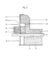
- a melt flow electrolysis cell for the production of aluminum has an outer steel trough 10.
- the lower insulation 12 and the lateral insulation 14 are embedded therein.
- the lower part 16 of the carbon lining with cast-in or embedded, iron cathode bars 18 is arranged on the lower insulation 12 forming the substructure .
- the approximately 8 cm thick layer 20 with low shear strength is arranged on the horizontally delimited edge region of the lower part 16 of the carbon lining. Between this layer 20 and the lower part 16 of the carbon lining there is - not visible - a base made of carbon felt, which is glued to the lower part 16 of the carbon lining.
- the upper part 22 of the carbon lining is glued to the layer 20 with low shear strength, it projects beyond the lower part laterally.
- the uppermost area is formed by stone blocks 24, which ensures an insulating tub shelf that protects against the effects of oxygen.
- Prestressed "crunch elements" 26 which are supported by a bulge of the steel trough 10, are arranged inside the steel trough 10, at the level of the upper region of the bottom of the carbon lining.
- the "crunch elements" 26 oppose the expanding lower part 16 of the carbon lining with a constant, path-independent resistance.
- a very good heat-conducting layer is designed as a collecting zone 30. It extends in the vertical direction, downward, beyond the layer 20 with low shear strength and extends partially along the lower part 16 of the carbon lining.
- a flexible wall 32 part of the side region of the steel tub 10 is replaced by a flexible wall 32.
- fabrics made of carbon fibers, which are combined in a layered construction with metal foils, can be used.
- the prestressed "crunch elements" 26 arranged outside the flexible wall 32 consist, as in FIG. 1, of packages of plastically deformable, vertically arranged tubes. Towards the outside, the "crunch elements" 26 are supported by a fixed abutment 28.
- a sliding layer can be arranged between the flexible wall 32 and the lateral insulation.
- Fig. 3 shows a block of carbon foam 20 lying on a carbon felt 34 with low shear strength. Because of the different expansion of the lower part 16 and the upper part 22 of the carbon lining, the layer 20 with low shear strength has cracked for the first time, liquid electrolyte has penetrated and partially solidified.
- the layer 20 with low shear strength has been torn once, according to FIG. 4 several times.
- the carbon felt 34 has partially dissolved after the repeated tearing and the solidified electrolyte 36 has advanced further to the outside.
Landscapes
- Chemical & Material Sciences (AREA)
- Engineering & Computer Science (AREA)
- Chemical Kinetics & Catalysis (AREA)
- Electrochemistry (AREA)
- Materials Engineering (AREA)
- Metallurgy (AREA)
- Organic Chemistry (AREA)
- Electrolytic Production Of Metals (AREA)
- Secondary Cells (AREA)
- Micro-Organisms Or Cultivation Processes Thereof (AREA)
- Immobilizing And Processing Of Enzymes And Microorganisms (AREA)
Applications Claiming Priority (2)
| Application Number | Priority Date | Filing Date | Title |
|---|---|---|---|
| CH4249/82A CH660030A5 (de) | 1982-07-12 | 1982-07-12 | Kathodenwanne einer aluminiumelektrolysezelle. |
| CH4249/82 | 1982-07-12 |
Publications (2)
| Publication Number | Publication Date |
|---|---|
| EP0099331A1 true EP0099331A1 (fr) | 1984-01-25 |
| EP0099331B1 EP0099331B1 (fr) | 1986-12-10 |
Family
ID=4272579
Family Applications (1)
| Application Number | Title | Priority Date | Filing Date |
|---|---|---|---|
| EP83810282A Expired EP0099331B1 (fr) | 1982-07-12 | 1983-06-24 | Cuve cathodique pour cellule d'électrolyse d'aluminium |
Country Status (11)
| Country | Link |
|---|---|
| US (1) | US4537671A (fr) |
| EP (1) | EP0099331B1 (fr) |
| JP (1) | JPS5923891A (fr) |
| AU (1) | AU1660983A (fr) |
| CA (1) | CA1215941A (fr) |
| CH (1) | CH660030A5 (fr) |
| DE (1) | DE3368292D1 (fr) |
| NO (1) | NO832497L (fr) |
| NZ (1) | NZ204762A (fr) |
| SU (1) | SU1308201A3 (fr) |
| ZA (1) | ZA834667B (fr) |
Cited By (2)
| Publication number | Priority date | Publication date | Assignee | Title |
|---|---|---|---|---|
| WO2012038427A1 (fr) * | 2010-09-20 | 2012-03-29 | Sgl Carbon Se | Cathode pour cellules d'électrolyse |
| ITVE20110026A1 (it) * | 2011-05-05 | 2012-11-06 | Tito Monticelli | Canalizzazione latente per forno elettrolitico per la produzione di al. da al2o3 + na3alf3. l'invenzione riguarda la realizzazione nella parte catodica di una vasca/forno standard a difesa dal danneggiamento provocato da corrosione prima, e da infilt |
Families Citing this family (5)
| Publication number | Priority date | Publication date | Assignee | Title |
|---|---|---|---|---|
| US4687566A (en) * | 1985-03-06 | 1987-08-18 | Swiss Aluminium Ltd. | Protective collar for anode spade pin |
| NO157462C (no) * | 1985-10-24 | 1988-03-23 | Hydro Aluminium As | Laminert karbonkatode for celler til smelte-elektrolytisk fremstilling av aluminium. |
| US4900249A (en) * | 1987-01-12 | 1990-02-13 | Dresser Industries, Inc. | Aluminum reverberatory furnace lining |
| EP2225492B1 (fr) * | 2007-12-22 | 2016-01-13 | Jünger + Gräter GmbH Feuerfestbau | Garnissage de paroi de fours industriels |
| DE102010041082A1 (de) * | 2010-09-20 | 2012-03-22 | Sgl Carbon Se | Kathode für Eletrolysezellen |
Citations (2)
| Publication number | Priority date | Publication date | Assignee | Title |
|---|---|---|---|---|
| GB1209541A (en) * | 1967-02-01 | 1970-10-21 | Montedison Spa | Electrolytic furnaces for the production of aluminium |
| DE2633055B1 (de) * | 1976-06-16 | 1977-12-08 | Alusuisse | Elektrolysezelle zur herstellung von aluminium |
Family Cites Families (3)
| Publication number | Priority date | Publication date | Assignee | Title |
|---|---|---|---|---|
| US3514520A (en) * | 1967-02-01 | 1970-05-26 | Montedison Spa | Linings of electrolysis,remelting,and similar furnaces,containing molten metals,alone or together with molten salts |
| CH643602A5 (de) * | 1979-10-17 | 1984-06-15 | Alusuisse | Elektrolysewanne. |
| US4339316A (en) * | 1980-09-22 | 1982-07-13 | Aluminum Company Of America | Intermediate layer for seating RHM tubes in cathode blocks |
-
1982
- 1982-07-12 CH CH4249/82A patent/CH660030A5/de not_active IP Right Cessation
-
1983
- 1983-06-24 DE DE8383810282T patent/DE3368292D1/de not_active Expired
- 1983-06-24 EP EP83810282A patent/EP0099331B1/fr not_active Expired
- 1983-06-27 ZA ZA834667A patent/ZA834667B/xx unknown
- 1983-06-30 NZ NZ204762A patent/NZ204762A/en unknown
- 1983-07-04 SU SU833612253A patent/SU1308201A3/ru active
- 1983-07-06 US US06/511,266 patent/US4537671A/en not_active Expired - Fee Related
- 1983-07-06 AU AU16609/83A patent/AU1660983A/en not_active Abandoned
- 1983-07-08 NO NO832497A patent/NO832497L/no unknown
- 1983-07-11 CA CA000432159A patent/CA1215941A/fr not_active Expired
- 1983-07-12 JP JP58126841A patent/JPS5923891A/ja active Pending
Patent Citations (2)
| Publication number | Priority date | Publication date | Assignee | Title |
|---|---|---|---|---|
| GB1209541A (en) * | 1967-02-01 | 1970-10-21 | Montedison Spa | Electrolytic furnaces for the production of aluminium |
| DE2633055B1 (de) * | 1976-06-16 | 1977-12-08 | Alusuisse | Elektrolysezelle zur herstellung von aluminium |
Cited By (3)
| Publication number | Priority date | Publication date | Assignee | Title |
|---|---|---|---|---|
| WO2012038427A1 (fr) * | 2010-09-20 | 2012-03-29 | Sgl Carbon Se | Cathode pour cellules d'électrolyse |
| RU2529432C1 (ru) * | 2010-09-20 | 2014-09-27 | Сгл Карбон Се | Катод для ячеек электролизера |
| ITVE20110026A1 (it) * | 2011-05-05 | 2012-11-06 | Tito Monticelli | Canalizzazione latente per forno elettrolitico per la produzione di al. da al2o3 + na3alf3. l'invenzione riguarda la realizzazione nella parte catodica di una vasca/forno standard a difesa dal danneggiamento provocato da corrosione prima, e da infilt |
Also Published As
| Publication number | Publication date |
|---|---|
| JPS5923891A (ja) | 1984-02-07 |
| US4537671A (en) | 1985-08-27 |
| NZ204762A (en) | 1986-05-09 |
| CH660030A5 (de) | 1987-03-13 |
| CA1215941A (fr) | 1986-12-30 |
| AU1660983A (en) | 1984-01-19 |
| EP0099331B1 (fr) | 1986-12-10 |
| ZA834667B (en) | 1984-03-28 |
| NO832497L (no) | 1984-01-13 |
| DE3368292D1 (en) | 1987-01-22 |
| SU1308201A3 (ru) | 1987-04-30 |
Similar Documents
| Publication | Publication Date | Title |
|---|---|---|
| DE2312439C2 (de) | Kathodenwanne einer Aluminiumschmelzflußelektrolysezelle | |
| DE1251962B (de) | Kathode fur eine Elektrolysezelle zur Herstellung von Aluminium und Verfahren zur Herstellung derselben | |
| DE2817202A1 (de) | Aus expandiertem graphit bestehende barriere am boden einer elektrolytischen zelle | |
| EP0099331B1 (fr) | Cuve cathodique pour cellule d'électrolyse d'aluminium | |
| EP2440688B1 (fr) | Plancher formant cathode, procédé de production d'un plancher formant cathode, et utilisation dudit plancher dans une cellule d'électrolyse pour la production d'aluminium | |
| DE2631673C3 (de) | Kathodenelement für Elektrolysezellen, insbesondere zur Aluminiumelektrolyse | |
| DE1533439A1 (de) | Elektrolytische Zelle zur Gewinnung von Aluminium und Verfahren zum Betrieb derselben | |
| DE3634076C2 (fr) | ||
| EP3472373B1 (fr) | Bloc cathodique présentant une géométrie à rainure | |
| CH647820A5 (de) | Unterteil einer schmelzflusselektrolysezelle. | |
| DE2633055C2 (de) | Elektrolysezelle zur Herstellung von Aluminium | |
| EP0052577B1 (fr) | Ancrage pour une barre cathodique | |
| EP2989235B1 (fr) | Bloc cathodique muni d'une rainure de profondeur variable et d'un dispositif de fixation | |
| EP0193491A1 (fr) | Cuve d'électrolyse | |
| DE1558726C3 (fr) | ||
| DE3135083C1 (de) | Elektrolysewanne zur Herstellung von Aluminium mittels Schmelzflusselektrolyse und Verfahren zum Einsetzen der Eisenbarren | |
| DE2162893A1 (de) | Boden für einen Schachtofen und Verfahren zum Kühlen desselben | |
| EP0109358A1 (fr) | Cathode pour cellule d'électrolyse à bain fondu | |
| EP0197003A1 (fr) | Cuve d'électrolyse pour la production d'aluminium | |
| EP3350358B1 (fr) | Fond servant de cathode destiné à la fabrication d'aluminium | |
| DE2833381A1 (de) | Elektrolysezelle zum gewinnen von aluminium | |
| DE2128220C3 (de) | Geschlossene elektrolytische Zelle | |
| CH663624A5 (en) | Cathode element of a cathode vessel for producing aluminium | |
| DE2312958A1 (de) | Verfahren zum vergiessen einer metallstange in einem kohleblock | |
| DE3044676A1 (de) | Verankerung fuer einen kathodenbarren |
Legal Events
| Date | Code | Title | Description |
|---|---|---|---|
| PUAI | Public reference made under article 153(3) epc to a published international application that has entered the european phase |
Free format text: ORIGINAL CODE: 0009012 |
|
| AK | Designated contracting states |
Designated state(s): AT CH DE FR GB IT LI NL SE |
|
| 17P | Request for examination filed |
Effective date: 19840629 |
|
| RBV | Designated contracting states (corrected) |
Designated state(s): CH DE GB LI |
|
| GRAA | (expected) grant |
Free format text: ORIGINAL CODE: 0009210 |
|
| AK | Designated contracting states |
Kind code of ref document: B1 Designated state(s): CH DE GB LI |
|
| REF | Corresponds to: |
Ref document number: 3368292 Country of ref document: DE Date of ref document: 19870122 |
|
| PG25 | Lapsed in a contracting state [announced via postgrant information from national office to epo] |
Ref country code: LI Effective date: 19870630 Ref country code: CH Effective date: 19870630 |
|
| PLBE | No opposition filed within time limit |
Free format text: ORIGINAL CODE: 0009261 |
|
| STAA | Information on the status of an ep patent application or granted ep patent |
Free format text: STATUS: NO OPPOSITION FILED WITHIN TIME LIMIT |
|
| 26N | No opposition filed | ||
| REG | Reference to a national code |
Ref country code: CH Ref legal event code: PL |
|
| PG25 | Lapsed in a contracting state [announced via postgrant information from national office to epo] |
Ref country code: DE Effective date: 19880301 |
|
| GBPC | Gb: european patent ceased through non-payment of renewal fee | ||
| PG25 | Lapsed in a contracting state [announced via postgrant information from national office to epo] |
Ref country code: GB Effective date: 19881122 |