EP0099346A2 - Gerät zum Hindurchtreiben oder Ziehen von langgestreckten draht- oder stabförmigen Elementen durch Leitungen - Google Patents
Gerät zum Hindurchtreiben oder Ziehen von langgestreckten draht- oder stabförmigen Elementen durch Leitungen Download PDFInfo
- Publication number
- EP0099346A2 EP0099346A2 EP83850177A EP83850177A EP0099346A2 EP 0099346 A2 EP0099346 A2 EP 0099346A2 EP 83850177 A EP83850177 A EP 83850177A EP 83850177 A EP83850177 A EP 83850177A EP 0099346 A2 EP0099346 A2 EP 0099346A2
- Authority
- EP
- European Patent Office
- Prior art keywords
- wire
- rod
- track
- opening
- conduit
- Prior art date
- Legal status (The legal status is an assumption and is not a legal conclusion. Google has not performed a legal analysis and makes no representation as to the accuracy of the status listed.)
- Granted
Links
Images


Classifications
-
- H—ELECTRICITY
- H02—GENERATION; CONVERSION OR DISTRIBUTION OF ELECTRIC POWER
- H02G—INSTALLATION OF ELECTRIC CABLES OR LINES, OR OF COMBINED OPTICAL AND ELECTRIC CABLES OR LINES
- H02G1/00—Methods or apparatus specially adapted for installing, maintaining, repairing or dismantling electric cables or lines
- H02G1/06—Methods or apparatus specially adapted for installing, maintaining, repairing or dismantling electric cables or lines for laying cables, e.g. laying apparatus on vehicle
- H02G1/08—Methods or apparatus specially adapted for installing, maintaining, repairing or dismantling electric cables or lines for laying cables, e.g. laying apparatus on vehicle through tubing or conduit, e.g. rod or draw wire for pushing or pulling
- H02G1/083—Methods or apparatus specially adapted for installing, maintaining, repairing or dismantling electric cables or lines for laying cables, e.g. laying apparatus on vehicle through tubing or conduit, e.g. rod or draw wire for pushing or pulling using lines, e.g. needles, rods or tapes
Definitions
- the invention refers to a device for pushing or pulling elongate, wire- or rod-shaped elements through conduits, a typical, but not limiting, example of application being the introduction of electrical conductors into conduits provided in the walls of a building.
- a single helical compression spring may be inserted between the loop and the adjacent first bead element to compensate possible undesired stretching of the wire, but otherwise the whole length of the wire is covered by closely adjacent bead elements.
- the bead elements may be elongate and have a spherical convex front face at one end and a funnel-shaped recess on the other end into which said front face of an adjacent element can be accomodated in order to achieve increased rigidity of the whole device.
- a conduit draw wire 100 defined by a plurality of distinct groups of beads, each group such as A, B, C, D consisting of at least two closely adjacent rigid beads or bead elements 101 inclusive a first end bead 101' a second end bead 101", slipped-on on a selected length L of a bendable cord or wire 11.
- Each group of beads is separated from the neighbouring group by an interspace Z in which a helical compression spring 12is mounted. It is not critical whether all groups comprise the same number of beads or not. Typically, approximately six groups may be provided on a wire 11 which is 2.5 m long.
- the beads are preferably somewhat longitudinal with a diameter of e.g. 10 mm and a length of e.g. 12 mm and have an axial bore 101a through which wire 11 with a diameter of e.g. 1.5 mm can pass freely.
- the helical springs may have approximately the same length as one bead and shall not have greater length than two beads.
- At least the end beads 101', 101", and at least at their side turned towards the neighbouring group may be according to Fig. 2 provided with a shallow recess 101b surrounding the orifice of the axial bore 101a and intended to accomodate an end part 12' of spring 12.
- spring 12 has turns with smaller diameter in its both end parts 12' than in the middle part 12", and recess 101b may be then made funnel-shaped to fit the shape of the spring. This arrangement facilitates assembly and has even favourable effects on the performance, but in principle the springs and/or the recesses may also have cylindrical cl other shape.
- wire 11 is at both its ends firmly anchored in end pieces, and length L is selected so that springs 12 constantly are somewhat compressed, as the outer end beads in the two outer groups bear against the end pieces.
- wire 11 is at one end anchored in a rigid eye member 15, defining one of said end pieces and to which the end of an electrical conductor which is to be drawn through a conduit can be hooked on.
- the end piece at the other end of wire 11 is, according to a preferred alternative, embodied by a short pin or rod 13 having an axis n and defining one part or member of a disengaging coupling 110.
- Rod 13 has a diameter h and a length a which at the utmost is equal to the diameter f of the bead elements 101.
- a second part or member of this coupling is defined by a coupling part 14' of a separate eye member 120 which further has a part 15' which in shape and function corresponds to eye member 15.
- Adraw wire element according to the present invention and having a length of 2.5 m may e.g. comprise seven groups with the following numbers of beads:25-40-40-40-40-40-25.
- the main effect of the plurality of the interspaces bridged by interposed helical springs is to make the device better apt to penetrate into conduits with several and/or sharp bends. It is of course easier to work with a device having just the required length than being forced to use always a "full-length" device which is 6 to 10 m long.
- the bead elements may either all be freely movable on wire 11, or individual bead elements at selected spacements may be affixed to wire 11 e.g. by being bonded thereto.
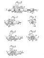
- the intermediate member 14 has a substantially cylindrical body 140 with rounded edges 140a', 140b' and in which two parallel, transversal, cylindrical bores 141 having axes v (Fig. 8) are provided, each adapted to receive one rod 13. Between each bore 141 and the adjacent end or front face 140a, 140b of body 140 extend grooves or passages 142 whose bottom 142a is located substantially at the longitudinal axis G of body 140, or, more precisely, half the diameter e of wire 11 beyond this axis.
- the grooves 142 have planar side walls 142b and a breadth b which at least corresponds to said diameter e and in any case is smaller than the diameter h of the rods 13.
- each groove 142 is at right angles connected a similar groove or passage 143 having planar side walls 143b (Fig. 6 , 7 ) and the same breadth (i.e. essentially equal to e) and depth as the grooves 142.
- the grooves 143 extend between the pertinent groove 142 and the mouth 141' (Fig. 8) of bore 141 at the side wall 140' of body 140.
- grooves 143 do not have any bottom, as they open below in the somewhat broader cylindrical bores 141 and do not continue beyond them.
- the central planes of symmetry of grooves 143 and bores 141 coincide.
- Grooves 143 may, however, either extend on both sides from the grooves 142 and thus also occupy the shadowed region N in Fig. 7, i.e. extend towards both orifices of each bore 141 as shown in Fig. 6 or, as shcvm in Fig. 5, both can extend towards the same side of body 140.
- the intermediate member 14 gets connected to a rod-shaped coupling member 13 by the latter being pushed into one of the bores 141 from that side where a groove 142 is provided, the wire 11 being lead in said groove 142.
- Member 14 is first held in a position where axis G as well as bore 141 subtend a right angle with wire 11 (according to e.g. Fig. 3, wire 11 would penetrate into groove 14 from below).
- a relative rotation of body 140 and wire 11 in the sense of arrow P is performed in order to bring wire 11 into the axial position shown in the Figs. 3 and 4 to 6.
- bore 141 must have an orifice at the surface of body 14 only on one side, and can also be defined by blind hole.
- the coupling part 14' of eye member 120 in Fig. 1 simply is one half of such an intermediate member 14, the other half having been replaced by the eye part 15'. It will be equally readily understood that instead of eye part 15' also any other desired element may be merged with one half of an intermediate member 14 and thus made attachable to the end of a selected number of interconnected lengths L.
- FIG. 9 an apparatus 200 for pushing or pulling an elongate bendable element such as conduit draw wire 100 of Fig. 1 through a conduit (not shown).
- the apparatus has an elongate body 20, e.g. substantially in the shape of a hollow cylindrical body having an outer wall 20a.
- a track or path 21 for a selected part (conveniently in the order of several decimeters) of respective element such as draw wire 100 provided.
- Track 21 is in the drawing shown to be rectilinear, but it may be also curved, e.g. in the drawing plane with at least one of its ends lying either higher or lower than the middle region thereof.
- Parallel with track 21 is another track 22, substantially equally long as track 21, provided which definesa running track for a runner or slider 23.
- Track 22 is in the example shown also rectilinear.
- An engagement hook 24 is pivoted to runner 23 with the aid of a pivot pin 24a and is affected by a spring 24b so as to engage element 100 when this is located in track 21.
- the inclination of hook 24 relative the tracks 21 and 22, and the shape of its free end are selected so as to enable for the free end to penetrate between two adjacent bead elements 101, and a stop 24c is provided to secure this inclination.
- apparatus 200 When apparatus 200 is intended for pushing element 100, the inclination of hook 24 will be in the direction of push E, as illustrated. When the apparatus 200 is to be used for pulling, either the inclination will be reversed, or simply the whole apparatus may be used in reversed position. Apparatus 200 as illustrated in Fig. 9 may thus be used either for pushing an element 100 into a conduit situated to the left, or pulling it out of a conduit situated to the right.
- spring 24b may be omitted, or that instead of a pivotally attached hook a resilient, projecting engagement hook may be fixedly attached to runner 23.
- the runner 23 is driven in track 22 by a handle 25, 25' - which either may be attached thereto with the aid of long rod 25'a, passing through track 22, as shown in phantom in the drawing, or by a shorter rod25a extending at right angles to track 22 and passing through an elongate slot 26 (Fig. 10 ) in body 20 and wall 20a,parallel with and adjacent to track 22, as shown in fulldrawn lines.
- hook 24 engages element 100 at each feeding stroke (in the sense of arrow E) and releases it at each return stroke (against the sense of arrow E).
- At at least one end 200a of body 20 may a curved feed--out spout 27 with U-shaped profile be rotarily mounted with the aid of an inner flange 27a affixed to the spout 27 and an annular outer flange 27b affixed to the body 20 and having an inner portion overlapping said outer edge and engaging it.
- the bottom of spout 27 is at the place of attachment to body 20 flush with the bottom of track 21.
- Conduit draw wire 100 may be introduced into track 22 from the rear end 200b of body 20 (where no spout is provided) until it becomes engaged by hook 24, whereupon runner 23 is with the aid of handle 25 or 25' reciprocated in track 26 so many times till a desired section of draw wire 100 has been fed out through spout 27 and fed in into a conduit to the orifice of which spout 27 has been brought.
- body 20 is according to Fig. 10 made in two parts 20a, 20b hinged together by a hinge means 28 so that it may be opened longitudinally and give free access to track 21 along the whole extent thereof.
- a locking means may be provided to secure parts 20a and 20b in the closed position.
- runner 23' defined by a cylindrical body provided with groove 23'a in which hook 24, pivot 24a and possibly also spring24b are arranged.
- Track 22' is then of course also cylindrical and a slot 22a for hook 24 interconnects the two tracks 21, 22'.
- Rod 25'a and handle 25' are preferably used, and runner 23', rod 25'a and handle 25' may be merged into one single component,and/or hook 24 may be embodied by a leaf spring affixed to runner 23' and passing through slot 22a into engagement with element 100.
- the main advantage of an apparatus 200 having a divided body 20 is that draw wire 100 can be taken out at any arbitrary location. If e.g. several conduits issue from one junction box, the draw wire may be first pushed through one of the conduits, then the apparatus can be opened and used for pushing the rear end of the same draw wire, or another draw wire, into another conduit leading from the same junction box.
- the engagement part proper of hook 24 may be readily shaped in known manner for engagement with a smooth surface such as that of a plastics draw wire described in the aforementioned Swedish patent 140 707,or of the conductor proper, as described in the aforementioned U.S.A. patent 1,959,490,or of any other wire or rod shape element with appreciable greater length than diameter.
- Such engagement hook 24' may have e.g. a grooved or knurled engagement edge 24" as shown in Fig. 12.
Landscapes
- Electric Cable Installation (AREA)
- Catalysts (AREA)
- Organic Low-Molecular-Weight Compounds And Preparation Thereof (AREA)
- Feeding Of Articles To Conveyors (AREA)
- Rigid Pipes And Flexible Pipes (AREA)
- Supports For Pipes And Cables (AREA)
Priority Applications (1)
| Application Number | Priority Date | Filing Date | Title |
|---|---|---|---|
| AT83850177T ATE30816T1 (de) | 1982-07-13 | 1983-06-22 | Geraet zum hindurchtreiben oder ziehen von langgestreckten draht- oder stabfoermigen elementen durch leitungen. |
Applications Claiming Priority (2)
| Application Number | Priority Date | Filing Date | Title |
|---|---|---|---|
| SE8204296A SE8204296L (sv) | 1982-07-13 | 1982-07-13 | Anordning for indragning av el-ledningar i installationsror |
| SE8204296 | 1982-07-13 |
Publications (3)
| Publication Number | Publication Date |
|---|---|
| EP0099346A2 true EP0099346A2 (de) | 1984-01-25 |
| EP0099346A3 EP0099346A3 (en) | 1984-08-01 |
| EP0099346B1 EP0099346B1 (de) | 1987-11-11 |
Family
ID=20347370
Family Applications (1)
| Application Number | Title | Priority Date | Filing Date |
|---|---|---|---|
| EP83850177A Expired EP0099346B1 (de) | 1982-07-13 | 1983-06-22 | Gerät zum Hindurchtreiben oder Ziehen von langgestreckten draht- oder stabförmigen Elementen durch Leitungen |
Country Status (9)
| Country | Link |
|---|---|
| US (1) | US4552338A (de) |
| EP (1) | EP0099346B1 (de) |
| JP (1) | JPS5925508A (de) |
| AT (1) | ATE30816T1 (de) |
| AU (1) | AU560611B2 (de) |
| DE (1) | DE3374499D1 (de) |
| FI (1) | FI832537L (de) |
| NO (1) | NO832535L (de) |
| SE (1) | SE8204296L (de) |
Families Citing this family (11)
| Publication number | Priority date | Publication date | Assignee | Title |
|---|---|---|---|---|
| US5011332A (en) * | 1988-11-14 | 1991-04-30 | Siemens Aktiengesellschaft | Apparatus and method for introducing a cable-like element into a pipe and elements suitable therefor |
| US5196929A (en) * | 1989-07-05 | 1993-03-23 | Olympus Optical Co., Ltd. | Display system of camera having tracking apparatus |
| US5884901A (en) * | 1997-03-17 | 1999-03-23 | Schilling; Daniel R. | Apparatus for threading electrical wires into flexible conduit |
| US5987684A (en) * | 1997-04-03 | 1999-11-23 | Phillip S. Evans | Urinal auger |
| NO311199B1 (no) * | 1998-01-21 | 2001-10-22 | Nexans | Anordning for å trekke en langstrakt artikkel gjennom et buet rör |
| DE10030985B4 (de) * | 2000-06-30 | 2004-02-19 | Igus Spritzgussteile für die Industrie GmbH | Leitungsführungseinrichtung |
| US6749179B2 (en) | 2002-03-13 | 2004-06-15 | Board Of Regents, The University Of Texas System | Devices and methods for placing wiring into split loom tubing |
| US6786473B1 (en) * | 2003-03-21 | 2004-09-07 | Home Comfort Zones, Inc. | String to tube or cable connector for pulling tubes or cables through ducts |
| US9537293B2 (en) | 2012-02-29 | 2017-01-03 | Encore Wire Corporation | Wire pulling head apparatus with crimp zone indicators and method of using same |
| US10569311B2 (en) | 2015-05-08 | 2020-02-25 | Moja Industries | Plumbing device and associated systems and methods |
| CN112082039B (zh) * | 2020-08-26 | 2022-05-17 | 安徽乾方检测技术有限公司 | 一种城市排水管道检测装置 |
Family Cites Families (9)
| Publication number | Priority date | Publication date | Assignee | Title |
|---|---|---|---|---|
| US1368665A (en) * | 1920-10-27 | 1921-02-15 | Charles H Strauss | Clasp |
| US1959490A (en) * | 1931-08-31 | 1934-05-22 | Mistelski Theodor | Wire pushing and pulling tool |
| US1963561A (en) * | 1931-11-19 | 1934-06-19 | George J Sanger | Drain pipe cleaner |
| US2160395A (en) * | 1937-07-06 | 1939-05-30 | William L Wettlaufer | Device for removing the heads of golf clubs |
| GB623519A (en) * | 1947-05-09 | 1949-05-18 | Modern Arms Company Ltd | Improved means for rigidly connecting rods, tubes and the like |
| CH279073A (de) * | 1949-08-26 | 1951-11-15 | Brunschweiler & Co A | Vorrichtung zum Einziehen eines flexiblen Stabes zum Nachziehen von Drähten usw. in ein Rohrgebilde, insbesondere in elektrische Unterputzleitungsrohre. |
| CH304515A (de) * | 1952-09-13 | 1955-01-15 | Kunsthorn Ind Ag Kiag Ges | Kabel zum Einziehen von Leitungsdrähten in Leitungsröhren. |
| US3185318A (en) * | 1963-07-10 | 1965-05-25 | Sr Rufus James Lewis | Orientation jack |
| US3645502A (en) * | 1969-08-08 | 1972-02-29 | Charles Stromp Jr | Rod and pipe pusher and puller |
-
1982
- 1982-07-13 SE SE8204296A patent/SE8204296L/ not_active Application Discontinuation
-
1983
- 1983-06-22 EP EP83850177A patent/EP0099346B1/de not_active Expired
- 1983-06-22 AT AT83850177T patent/ATE30816T1/de not_active IP Right Cessation
- 1983-06-22 DE DE8383850177T patent/DE3374499D1/de not_active Expired
- 1983-06-30 US US06/509,968 patent/US4552338A/en not_active Expired - Fee Related
- 1983-07-04 AU AU16533/83A patent/AU560611B2/en not_active Expired - Fee Related
- 1983-07-11 JP JP58124863A patent/JPS5925508A/ja active Pending
- 1983-07-12 FI FI832537A patent/FI832537L/fi not_active Application Discontinuation
- 1983-07-12 NO NO832535A patent/NO832535L/no unknown
Also Published As
| Publication number | Publication date |
|---|---|
| SE8204296L (sv) | 1984-01-14 |
| EP0099346A3 (en) | 1984-08-01 |
| AU1653383A (en) | 1984-01-19 |
| DE3374499D1 (en) | 1987-12-17 |
| AU560611B2 (en) | 1987-04-09 |
| JPS5925508A (ja) | 1984-02-09 |
| US4552338A (en) | 1985-11-12 |
| EP0099346B1 (de) | 1987-11-11 |
| NO832535L (no) | 1984-01-16 |
| FI832537A7 (fi) | 1984-01-14 |
| FI832537L (fi) | 1984-01-14 |
| ATE30816T1 (de) | 1987-11-15 |
| SE8204296D0 (sv) | 1982-07-13 |
| FI832537A0 (fi) | 1983-07-12 |
Similar Documents
| Publication | Publication Date | Title |
|---|---|---|
| EP0099346B1 (de) | Gerät zum Hindurchtreiben oder Ziehen von langgestreckten draht- oder stabförmigen Elementen durch Leitungen | |
| US5791022A (en) | Cord locking mechanism | |
| WO2013068988A4 (de) | Leitungstransportvorrichtung | |
| US2998743A (en) | Toggle bolt | |
| DE3710922C1 (de) | Zange zum Verschieben von flexiblem Strangmaterial | |
| US2693029A (en) | Scraper blade holder | |
| US4819855A (en) | Tag-pin attaching apparatus | |
| DE19714964C1 (de) | Zuführeinrichtung für gegurtete elektrische Kontakte | |
| US4561349A (en) | Variable length guide device for a pushed wire | |
| US4027369A (en) | Element rows coupling tool for a concealed slide fastener | |
| US3280435A (en) | Systems for linking the ends of material | |
| GB2180293A (en) | Connectors for use with strapping | |
| CA1233433A (en) | Wire sorting | |
| ES265387U (es) | Mecanismo para cortinas. | |
| US2176863A (en) | Key case | |
| US5907901A (en) | Wire lead-in funnel for a terminal applicator | |
| US2909302A (en) | Riveting gun | |
| CN113386683A (zh) | 布线装置及座椅系统 | |
| US2836165A (en) | Archery bow | |
| CN117096795B (zh) | 一种电缆固定器 | |
| DE1893615U (de) | Steckkupplung fuer lichtleiter od. dgl. von endoskopen. | |
| CN216162737U (zh) | 电子卡托盘 | |
| CN209604366U (zh) | 一种隔热罩连接结构 | |
| SE434618B (sv) | Forfarande och anordning for formning av en hektorganfri lengdsektion i ett dragkedjeemne | |
| DE2802766A1 (de) | Schraubendreher mit festhaltevorrichtung fuer schrauben |
Legal Events
| Date | Code | Title | Description |
|---|---|---|---|
| PUAI | Public reference made under article 153(3) epc to a published international application that has entered the european phase |
Free format text: ORIGINAL CODE: 0009012 |
|
| AK | Designated contracting states |
Designated state(s): AT BE CH DE FR GB IT LI NL SE |
|
| PUAL | Search report despatched |
Free format text: ORIGINAL CODE: 0009013 |
|
| AK | Designated contracting states |
Designated state(s): AT BE CH DE FR GB IT LI NL SE |
|
| 17P | Request for examination filed |
Effective date: 19840822 |
|
| GRAA | (expected) grant |
Free format text: ORIGINAL CODE: 0009210 |
|
| AK | Designated contracting states |
Kind code of ref document: B1 Designated state(s): AT BE CH DE FR GB IT LI NL SE |
|
| PG25 | Lapsed in a contracting state [announced via postgrant information from national office to epo] |
Ref country code: NL Effective date: 19871111 Ref country code: LI Effective date: 19871111 Ref country code: IT Free format text: LAPSE BECAUSE OF FAILURE TO SUBMIT A TRANSLATION OF THE DESCRIPTION OR TO PAY THE FEE WITHIN THE PRESCRIBED TIME-LIMIT;WARNING: LAPSES OF ITALIAN PATENTS WITH EFFECTIVE DATE BEFORE 2007 MAY HAVE OCCURRED AT ANY TIME BEFORE 2007. THE CORRECT EFFECTIVE DATE MAY BE DIFFERENT FROM THE ONE RECORDED. Effective date: 19871111 Ref country code: CH Effective date: 19871111 Ref country code: BE Effective date: 19871111 Ref country code: AT Effective date: 19871111 |
|
| REF | Corresponds to: |
Ref document number: 30816 Country of ref document: AT Date of ref document: 19871115 Kind code of ref document: T |
|
| REF | Corresponds to: |
Ref document number: 3374499 Country of ref document: DE Date of ref document: 19871217 |
|
| ET | Fr: translation filed | ||
| REG | Reference to a national code |
Ref country code: CH Ref legal event code: PL |
|
| NLV1 | Nl: lapsed or annulled due to failure to fulfill the requirements of art. 29p and 29m of the patents act | ||
| PLBE | No opposition filed within time limit |
Free format text: ORIGINAL CODE: 0009261 |
|
| STAA | Information on the status of an ep patent application or granted ep patent |
Free format text: STATUS: NO OPPOSITION FILED WITHIN TIME LIMIT |
|
| 26N | No opposition filed | ||
| PG25 | Lapsed in a contracting state [announced via postgrant information from national office to epo] |
Ref country code: GB Effective date: 19890622 |
|
| PG25 | Lapsed in a contracting state [announced via postgrant information from national office to epo] |
Ref country code: SE Effective date: 19890623 |
|
| GBPC | Gb: european patent ceased through non-payment of renewal fee | ||
| PG25 | Lapsed in a contracting state [announced via postgrant information from national office to epo] |
Ref country code: FR Free format text: LAPSE BECAUSE OF NON-PAYMENT OF DUE FEES Effective date: 19900228 |
|
| PG25 | Lapsed in a contracting state [announced via postgrant information from national office to epo] |
Ref country code: DE Effective date: 19900301 |
|
| REG | Reference to a national code |
Ref country code: FR Ref legal event code: ST |
|
| EUG | Se: european patent has lapsed |
Ref document number: 83850177.3 Effective date: 19900418 |