EP0099461A1 - Selektive Erdschlussschutzschaltung für eine Hochspannungskabelstrecke - Google Patents
Selektive Erdschlussschutzschaltung für eine Hochspannungskabelstrecke Download PDFInfo
- Publication number
- EP0099461A1 EP0099461A1 EP83105460A EP83105460A EP0099461A1 EP 0099461 A1 EP0099461 A1 EP 0099461A1 EP 83105460 A EP83105460 A EP 83105460A EP 83105460 A EP83105460 A EP 83105460A EP 0099461 A1 EP0099461 A1 EP 0099461A1
- Authority
- EP
- European Patent Office
- Prior art keywords
- esv
- earth fault
- oer
- signal processing
- relay
- Prior art date
- Legal status (The legal status is an assumption and is not a legal conclusion. Google has not performed a legal analysis and makes no representation as to the accuracy of the status listed.)
- Granted
Links
- 238000012545 processing Methods 0.000 claims abstract description 28
- 238000012544 monitoring process Methods 0.000 claims description 6
- 230000007935 neutral effect Effects 0.000 abstract 3
- 238000013461 design Methods 0.000 description 2
- 238000000034 method Methods 0.000 description 2
- 238000006243 chemical reaction Methods 0.000 description 1
- 238000011161 development Methods 0.000 description 1
- 238000006073 displacement reaction Methods 0.000 description 1
- 230000001939 inductive effect Effects 0.000 description 1
- 230000001681 protective effect Effects 0.000 description 1
- 238000010791 quenching Methods 0.000 description 1
- 230000000171 quenching effect Effects 0.000 description 1
- 230000008054 signal transmission Effects 0.000 description 1
- 230000001960 triggered effect Effects 0.000 description 1
- 238000004804 winding Methods 0.000 description 1
Images
Classifications
-
- H—ELECTRICITY
- H02—GENERATION; CONVERSION OR DISTRIBUTION OF ELECTRIC POWER
- H02H—EMERGENCY PROTECTIVE CIRCUIT ARRANGEMENTS
- H02H3/00—Emergency protective circuit arrangements for automatic disconnection directly responsive to an undesired change from normal electric working condition with or without subsequent reconnection ; integrated protection
- H02H3/38—Emergency protective circuit arrangements for automatic disconnection directly responsive to an undesired change from normal electric working condition with or without subsequent reconnection ; integrated protection responsive to both voltage and current; responsive to phase angle between voltage and current
-
- H—ELECTRICITY
- H02—GENERATION; CONVERSION OR DISTRIBUTION OF ELECTRIC POWER
- H02H—EMERGENCY PROTECTIVE CIRCUIT ARRANGEMENTS
- H02H3/00—Emergency protective circuit arrangements for automatic disconnection directly responsive to an undesired change from normal electric working condition with or without subsequent reconnection ; integrated protection
- H02H3/26—Emergency protective circuit arrangements for automatic disconnection directly responsive to an undesired change from normal electric working condition with or without subsequent reconnection ; integrated protection responsive to difference between voltages or between currents; responsive to phase angle between voltages or between currents
- H02H3/28—Emergency protective circuit arrangements for automatic disconnection directly responsive to an undesired change from normal electric working condition with or without subsequent reconnection ; integrated protection responsive to difference between voltages or between currents; responsive to phase angle between voltages or between currents involving comparison of the voltage or current values at two spaced portions of a single system, e.g. at opposite ends of one line, at input and output of apparatus
- H02H3/30—Emergency protective circuit arrangements for automatic disconnection directly responsive to an undesired change from normal electric working condition with or without subsequent reconnection ; integrated protection responsive to difference between voltages or between currents; responsive to phase angle between voltages or between currents involving comparison of the voltage or current values at two spaced portions of a single system, e.g. at opposite ends of one line, at input and output of apparatus using pilot wires or other signalling channel
Definitions
- the invention relates to a selective earth fault protection circuit for a high-voltage cable section, at the ends of which a circuit breaker with a tripping device and the zero current and zero voltage transducers are provided.
- an earth fault is not detected by the built-in line protection devices, for example overcurrent protection, distance protection, etc., and is therefore not switched off.
- the line or cable section subject to earth faults must first be located. After the earth fault location has been located, the disconnection can be carried out.
- Locating the line or cable section with a ground fault can be quite time-consuming, especially in large-scale high-voltage networks. In general, the location of the earth fault takes a few hours. The thermal impact of an earth leakage arc can, for example, cause great damage to cables laid in bridges. An earth fault must be switched off after 30 s at the latest.
- the invention has for its object to provide a selective earth fault protection circuit with which an earth fault on the high-voltage cable route is quickly detected and switched off.
- each circuit breaker is a signal processing Direction is assigned in the form of a logic logic circuit, of which two inputs are connected to the outputs of an earth fault directional relay fed from the transducers, and a third input via a device measuring the measured variable of the voltage converter to which the zero voltage detecting transducer is connected, and two connections for an information channel assigned to both signal processing devices is provided.
- the advantage of this arrangement is that the faulty line is automatically and selectively reported immediately after the error has occurred, in contrast to known arrangements in which it had to be determined from a number of messages from the staff in the load distributor.
- the device that detects the measured variable of the voltage transformer is a threshold switch, in particular a Sc-hmitt trigger. It is thus advantageously achieved that the direction of the harmonic currents is only measured when the threshold value of the displacement voltage is exceeded. This prevents the protective device from responding incorrectly due to beats during normal operation of the network.
- the earth fault directional relay is a relay which responds to the harmonics occurring in the lines in the event of an earth fault.
- the harmonic currents are influenced neither in their size nor in their direction by the 50 Hz zero currents or by the quenching coils.
- the invention has the feature that the signal processing device designed as a logic logic circuit contains two AND elements, each of which a relay is assigned, one of which is used to monitor the output signals and one for monitoring the information channel is provided.
- the information channel is an auxiliary wire circuit connecting the two signal processing devices, which is routed in each signal processing device via a contact of the relay monitoring the information channel.
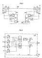
- FIG. 1 shows a basic design of the earth fault protection circuit
- FIG. 2 shows a more precise design of a signal processing device used in the protection circuit.
- Fig. 1 two network stations A, B are indicated, between which there is the three-phase high-voltage cable section HKS to be protected against ground faults;
- a circuit breaker LS, LS 'with tripping coils S, S' is arranged at each end of the cable section, with which the cable section can be switched off.
- the network variables - current and voltage - are sogn. Zero system needed. According to the theory of symmetrical components, the zero system is decisive for the earth fault determination.
- the measured value proportional to zero current is taken from current transformers l w , 1 w '(for example cable conversion current transformers) in a so-called total current circuit and the measured variable proportional to zero voltage is taken from the auxiliary winding of voltage transformers U wl UW connected in the open area.
- Each end of the cable route HKS is a threshold switch UST, UST ', for example in the form of a Schmitt trigger, an earth fault direction relay OER, OER' which determines the earth fault direction from the harmonics of the network, and a downstream Si Signal processing device ESV, ESV 'assigned; Both devices ESV, ESV 'are designed in the form of a logic combination circuit and connected via an auxiliary wire circuit HAV, which is influenced by them.
- the threshold value switches UST, UST 'monitor the value of the zero-proportional measured variable which occurs in the case of an earth fault in the high-voltage network.
- the threshold value for example 25 V
- a signal U, 9 Uö is generated, which is fed to the signal processing device ESV, ESV 'for further processing.
- the harmonic components which are either the harmonic components of the harmonics or the harmonics supplied externally by means of the ripple control system are first filtered out from the zero-current and zero-voltage-proportional measured variable. Then the reactive power is determined, which is taken as a criterion for the direction of the earth fault.
- the earth fault point is in the direction of the line or in the direction of the busbar if the reactive power is inductive or capacitive.
- the use of the mains harmonic is advantageous because the earth fault compensation is only matched to the compensation of the zero-current proportional measured variable with the mains fundamental.
- the harmonic earth fault directional relays emit an output signal E-Ltg, E-Ltg 'or E-SS, E-SS' when the earth fault in the direction of the line or in the direction of the busbar is detected.
- the output signal is fed to the signal processing device ESV, ESV '.
- the signal processing devices ESV, ESV 'in the form of logical logic circuits with the auxiliary wire circuit HAV have the task of detecting only earth faults on the cable section to be protected and switching them off with the command AUSK, AUSK' and / or a selective message to initiate switching processes to deliver.
- the auxiliary wire circuit HAV is only on one end, for example in station A, connected to an auxiliary DC voltage L + and L-. At the other end, in station B, the two auxiliary wires are connected to one another so that a closed current loop is formed.
- the signal U, U 'of the threshold switch UST, UST' is fed to the level converter PU1; the level converter PU2 the signal E-Ltg, E-Ltg 'of the earth fault direction relay OER, OER'; the level converter PU5, the signal E-SS, E-SS 'of the earth fault directional relay OER, OER' and the one connection a of the level converter PU4 of the one signal processing device, for example ESV, the positive pole L + of a voltage source, not shown, while the other connection b is led to a line c in which the normally closed contact of the relay K2 is located.
- the connection e of the signal processing device ESV is connected via one of the auxiliary wires g (FIG. 1) to the connection a 'of the level converter PU4' of the other signal processing device ESV ', the connection e' of which is connected to the negative pole L- Voltage source is connected.
- the AND gate UG1 is controlled by the level converters PU1 to PU4; the input of the AND gate UG1 connected to the level converter PU5 is negated.
- a signal corresponding to L occurs at the output of the AND gate UG1 if a signal U o corresponding to L from the threshold switch UST and a signal E-Ltg corresponding to L from the earth fault directional relay OER and a signal corresponding to L (L +) from the auxiliary wire circuit HAV (contacts d closed) and the earth fault control relay OER a signal corresponding to 0 is output.
- the delay element is started with an adjustable switch-on delay VG1 and, after the delay time has elapsed, the relay K1 is triggered, with the normally open contact f of which the OFF command AUSK is formed for the respective circuit breaker (FIG. 1).
- the signal corresponding to L of the auxiliary wire circuit HAV closed
- the AND gate UG2 is controlled by the level converters PU1 to PU3; the input of the AND gate UG2 connected to the level converter PU2 is negated.
- a signal corresponding to L occurs at the output of the AND gate UG2 if a signal U corresponding to L is output by the threshold switch UST and a signal E-SS corresponding to L and a signal E-Ltg corresponding to 0 is output by the earth fault directional relay OER.
- the relay K2 is activated and the associated normally closed contact d is opened and the auxiliary wire circuit HAV is interrupted.
- This interruption acts as a signal corresponding to 0 on the level converter PU4 of the respective other signal processing device ESV, which is thus de-energized on the input side, so that at its output the previous signal corresponding to L (since the harmonic earth fault direction relay UER has detected an earth fault in the direction of the line) changes to corresponding 0, so that the AND gate UG1 is blocked, the downstream relay K1 can not respond and thus not the on-off status of the circuit breaker LS (Fig.1) is changed.
- the delay element VG1 is provided in order to cause the respective circuit breaker to open only when the earth fault is stationary.
- the delay time can be set and is, for example, between approximately 1 and 10 s.
- the auxiliary wire circuit HAV connecting the two signal processing devices is not absolutely necessary.
- a transmit / receive channel can be used for this, for example using the radio path.
- the signal processing device ESV assigned to station A sends, for example, the information U o , E-Ltg, E-SS at the inputs h, i, j of the AND gate UG1 to the signal processing device ESV 'assigned to station B; if this device has determined that the earth fault is in the direction of the busbar, then this signal processing device ESV 'does not send any information to the signal processing device ESV assigned to station A, so that the circuit breaker LS assigned to it maintains its switching state unchanged.
Landscapes
- Engineering & Computer Science (AREA)
- Power Engineering (AREA)
- Emergency Protection Circuit Devices (AREA)
Abstract
Description
- Die Erfindung bezieht sich auf eine selektive Erdschlußschutzschaltung für eine Hochspannungskabelstrecke, an deren Enden je ein Leistungsschalter mit Auslöseeinrichtung sowie den Nullstrom und die Nullspannung erfassende Wandler vorgesehen sind.
- In Hochspannungsnetzen mit Erdschlußkompensation wird ein Erdschluß von den eingebauten Netzschutzeinrichtungen, beispielsweise Überstromzeitschutz, Distanzschutz usw., nicht erfaßt und daher nicht abgeschaltet. Die erdschlußbehaftete Leitungs- bzw. Kabelstrecke muß zuerst geortet werden. Nachdem die Erdschlußstelle lokalisiert ist, kann die Abschaltung vorgenommen werden.
- Die Ortung der erdschlußbehafteten Leitungs- bzw. Kabelstrecke kann, insbesondere in weit ausgedehnten Hochspannungsnetzen, recht zeitaufwendig sein. Im allgemeinen dauert die Lokalisierung der Erdschlußstelle einige Stunden. Die thermische Auswirkung eines Erdschluß-Lichtbogens kann beispielsweise bei in Brücken verlegten Kabelstrecken große Schäden verursachen. Hier muß ein Erdschluß spätestens nach 30 s abgeschaltet werden.
- Der Erfindung liegt die Aufgabe zugrunde, eine selektive Erdschlußschutzschaltung zu schaffen, mit der ein Erdschluß auf der Hochspannungskabelstrecke schnell erfaßt und abgeschaltet wird.
- Diese Aufgabe wird erfindungsgemäß dadurch gelöst, daß jedem Leistungsschalter eine Signalverarbeitungseinrichtung in Form einer logischen Verknüpfungsschaltung zugeordnet ist, von der zwei Eingänge an die Ausgänge eines aus den Wandlern gespeisten Erdschlußrichtungsrelais angeschlossen sind, und ein dritter Eingang über eine die Meßgröße des Spannungswandlers erfassende Einrichtung mit dem die Nullspannung erfassenden Wandler verbunden ist, und zwei Anschlüsse für einen beide Signalverarbeitungseinrichtungen gemeinsam zugeordneten Informationskanal vorgesehen sind.
- Der Vorteil dieser Anordnung ist der, daß die erschlußbehaftete Leitung sofort nach Eintritt des Fehlers automatisch selektiv gemeldet wird, im Gegensatz zu bekannten Anordnungen, bei denen sie aus einer Anzahl von Meldungen vom Personal im Lastverteiler eruiert werden mußten.
- Gemäß einem weiteren Merkmal der Erfindung ist vorgesehen, daß die die Meßgröße des Spannungswanders erfassende Einrichtung ein Schwellenwertschalter, insbesondere ein Sc-hmitt-Trigger ist. Damit wird vorteilhafter Weise erreicht, daß die Messung der Richtung der Oberwellenströme erst bei Überschreitung des Schwellenwertes der Verlagerungsspannung erfolgt. Dadurch wird ein fehlerhaftes Ansprechen der Schutzeinrichtung durch Schwebungen im Normalbetrieb des Netzes vermieden.
- Eine weitere vorteilhafte Weiterbildung ist dadurch gekennzeichnet, daß das Erdschlußrichtungsrelais ein auf die bei Erdschluß in den Leitungen auftretenden Oberwellen ansprechendes Relais ist. Die Folge davon ist, daß die Oberwellenströme weder in ihrer Größe noch in ihrer Richtung durch die 50 Hz-Nullströme bzw. durch die Löschspulen beeinflußt werden.
- Zur Abgabe einer logisch selektiven Meldung und zur Richtungskontrolle der Oberwellenströme weist die Erfindung das Merkmal auf, daß die als logische Verknüpfungsschaltung ausgebildete Signalverarbeitungseinrichtung zwei UND-Glieder enthält, denen je ein Relais zugeordnet ist, von denen eines zur Überwachungs des Ausgangssignals und eines zur Überwachung des Informationskanals vorgesehen ist.
- Ein weiteres vorteilhaftes Merkmal der Erfindung besteht schließlich darin, daß der Informationskanal ein die beiden Signalverarbeitungseinrichtungen verbindender Hilfsaderschaltkreis ist, der in jeder Signalverarbeitungseinrichtung über einen Kontakt des den Informationskanal überwachenden Relais geführt ist. Daraus ergibt sich der Vorteil, daß sowohl für die Signalübertragung als auch für die Signalkanalüberwachung nur ein einziges Kabel erforderlich ist.
- Die Erfindung wird nachstehend an Hand eines in der Zeichnung schematisch dargestellten Ausführungsbeispieles näher erläutert. Es zeigen Fig. 1 eine prinzipielle Ausbildung der Erdschlußschutzschaltung und Fig. 2 eine genauere Ausbildung einer bei der Schutzschaltung verwendeten Signalverarbeitungs-Einrichtung. In Fig. 1 sind zwei Netzstationen A, B angedeutet, zwischen denen sich die gegen Erdschluß zu schützende Dreiphasen-Hochspannungskabelstrecke HKS befindet; an jedem Ende der Kabelstrecke ist ein Leistungsschalter LS, LS' mit Auslösespulen S, S' angeordnet, mit dem die Kabelstrecke abgeschaltet werden kann.
- Zur Erfassung der Erdschlußrichtung werden die Netzgrößen - Strom und Spannung - im sogn. Nullsystem benötigt. Entsprechend der Theorie der symmetrischen Komponenten ist das Nullsystem für die Erdschlußermittlung maßgebend. Die nullstromproportionale Meßgröße wird aus Stromwandlern lw, 1w' (beispielsweise Kabelumbau-Stromwandler) in sogenannter Summenstromschaltung und die nullspannungsproportionale Meßgröße aus der in offenem Bereich geschalteten Hilfswicklung von Spannungswandlern Uwl UW entnommen.
- Jedem Ende der Kabelstrecke HKS ist ein Schwellenwertschalter UST, UST' beispielsweise in Form eines Schmitt-Triggers, ein die Erdschlußrichtung aus den Oberschwingungen des Netzes ermittelndes Erdschlußrichtungsrelais OER, OER' und eine diesen nachgeordnete Signalverarbeitungseinrichtung ESV, ESV' zugeordnet; beide Einrichtungen ESV, ESV' sind in Form einer logischen Verknüpfungsschaltung ausgeführt und über einen Hilfsadern- Schaltkreis HAV verbunden, der von ihnen beeinflußt wird.
- Mit den Schwellwertschaltern UST, UST' wird der Wert der nullproportionalen Meßgröße überwacht, die bei einem Erdschluß-im Hochspannungsnetz auftritt. Wenn der Schwellwert (beispielsweise 25 V) erreicht ist, wird ein Signal U,9 Uö erzeugt, das der Signalverarbeitungs-Einrichtung ESV, ESV' zur Weiterverarbeitung zugeführt wird.
- Die Oberschwingungs-Erdschlußrichtungsrelais OER, OER' dienen zur Richtungserfassung der Erdschlußstelle. Hiezu werden zunächst aus der nullstrom- und nullspannungsproportionalen Meßgröße die Oberschwingungsanteile herausgefiltert, die entweder die netzharmonischen oder die mittels Rundsteueranlage fremdeingespeisten Oberschwingungen sind. Anschließend wird die Blindleistung ermittelt, die als Kriterium für die Richtung der Erdschlußstelle genommen wird. Die Erdschlußstelle befindet sich in Richtung Leitung bzw. in Richtung Sammelschiene, wenn die Blindleistung induktiv bzw. kapazitiv ist. Die Verwendung der Netzoberschwingung ist vorteilhaft, weil die Erdschlußkompensation nur auf die Kompensation der nullstromproportionalen Meßgröße mit der Netzgrundschwingung abgestimmt ist. Die Oberschwingungs-Erdschlußrichtungsrelais geben ein Ausgangssignal E-Ltg, E-Ltg' oder E-SS, E-SS' ab, wenn der Erdschluß in Richtung Leitung oder in Richtung Sammelschiene festgestellt wird. Das Ausgangssignal wird der Signalverarbeitungs-Einrichtung ESV, ESV' zugeführt.
- Die Signalverarbeitungs-Einrichtungen ESV, ESV' in Form logischer Verknüpfungsschaltungen mit dem Hilfsadern-Schaltkreis HAV haben die Aufgabe, nur Erdschlüsse auf der zu schützenden Kabelstrecke zu erfassen und mit dem Auskommando AUSK, AUSK' abzuschalten und/oder eine selektive Meldung zur Einleitung von Umschaltvorgängen abzugeben. Der Hilfsadern-Schaltkreis HAV ist nur an einem Ende, beispielsweise in der Station A, an eine Hilfsgleichspannung L+ und L- angeschlossen. Am anderen Ende, in der Station B, sind die beiden Hilfsadern miteinander verbunden, so daß eine geschlossene Stromschleife gebildet ist.
- Wie aus Fig. 2 ersichtlich, umfaßt jede Signalverarbeitungs-Einrichtung ESV, ESV' vier Pegelumsetzer PU1 bis PU4, beispielsweise in Form von Optokopplern, ein UND-Glied UG1 mit nachgeordnetem Verzögerungsglied VG1 und Relais K1 mit Arbeitskontakt f, ein weiteres UND-Glied UG2, das ein weiteres Relais K2 mit Ruhekontakt d ansteuert.
- Dem Pegelumsetzer PU1 wird das Signal U , U ' des Schwellwertschalters UST, UST' zugeführt; dem Pegelumsetzer PU2 das Signal E-Ltg, E-Ltg' des Erdschlußrichtungsrelais OER, OER'; dem Pegelumsetzer PU5 das Signal E-SS, E-SS' des Erdschlußrichtungsrelais OER, OER' und dem einen Anschluß a des Pegelumsetzers PU4 der einen Signalverarbeitungs-Einrichtung, beispielsweise ESV, der Pluspol L+ einer nicht weiter dargestellten Spannungsquelle, während der andere Anschluß b an eine Leitung c geführt ist, in der der Ruhekontakt des Relais K2 liegt. Der Anschluß e der Signalverarbeitungs-Einrichtung ESV ist über eine der Hilfsadern g (Fig.1) mit dem Anschluß a' des nicht weiter dargestellten Pegelumsetzers PU4' der anderen Signalverarbeitungs-Einrichtung ESV' verbunden, deren Anschluß e' mit dem Minuspol L- der Spannungsquelle verbunden ist.
- Wie aus Fig. 2 ersichtlich, wird das UND-Glied UG1 von den Pegelumsetzern PU1 bis PU4 angesteuert; der mit dem Pegelumsetzer PU5 verbundene Eingang des UND-Gliedes UG1 ist negiert. Am Ausgang des UND-Gliedes UG1 tritt ein Signal entsprechend L auf, wenn vom Schwellwertschalter UST ein Signal Uo entsprechend L und vom Erdschlußrichtungsrelais OER ein Signal E-Ltg entsprechend L und vom Hilfsadern-Schaltkreis HAV ein Signal entsprechend L(L+) (Kontakte d geschlossen) sowie vom Erdschlußrichtungsrelais OER ein Signal entsprechend 0 ausgegeben wird. In diesem Fall wird das Verzögerungsglied mit einstellbarer Einschaltverzögerung VG1 gestartet und nach Ablauf der Verzögerungszeit das Relais K1 angesteuert, mit dessen Arbeitskontakt f das Aus-Kommando AUSK für den jeweiligen Leistungsschalter (Fig. 1) gebildet wird. Durch die Berücksichtigung des Signals entsprechend L des Hilfsadern-Schaltkreises HAV (geschlossen, ist sichergestellt, daß eine Ausschaltung erst vorgenommen wird, wenn keines der beiden Oberschwingungs-Erd- schlul3richtungsrelais OER, OER' eine Erdschlußstelle in Richtung Sammelschiene feststellt.
- Wie weiter aus Fig. 2 ersichtlich, wird das UND-Glied UG2 von den Pegelumsetzern PU1 bis PU3 angesteuert; der mit dem Pegelumsetzer PU2 verbundene Eingang des UND-Gliedes UG2 ist negiert. Am Ausgang des UND-Gliedes UG2 tritt ein Signal entsprechend L auf, wenn vom Schwellwertschalter UST ein Signal U entsprechend L und vom Erdschlulßrichtungsrelais OER ein Signal E-SS entsprechend L und ein Signal E-Ltg entsprechend 0 ausgegeben wird. In diesem Fall wird das Relais K2 angesteuert und der zugeordnete Ruhekontakt d geöffnet und der Hilfsadern-Schaltkreis HAV unterbrochen. Damit wird eine absichtliche Unterbrechung des Hilfsadern-Schaltkreises HAV vorgenommen, wenn bei einem Erdschluß vom jeweiligen Oberschwingungs-Erdschlußrichtungsrelais, beispielsweise OER die Erdschlußstelle in Richtung Sammelschiene festgestellt wird. Diese Unterbrechung wirkt als Signal entsprechend 0 auf den Pegelumsetzer PU4 der jeweilig anderen Slgnalverarbeitungs-Einrichtung ESV, der damit eingangsseitig spannungslos wird, so daß an dessen Ausgang das bisherige Signal entsprechend L (da das Oberschwingungs-Erdschlußrichtungsrelais UER einen Erdschluß in Richtung Leitung festgestellt hat) in entsprechend 0 wechselt, so daß das UND-Glied UG1 blockiert wird, das nachgeordnete Relais K1 nicht ansprechen kann und damit auch nicht der Ein-Zustand des Leistungsschalters LS (Fig.1) geändert wird.
- beim Erdschluß treten Ausgleichsvorgänge mit Oberschwingungen auf; das Verzögerungsglied VG1 ist vorgesehen, um eine Ausschaltung des jeweiligen Leistungsschalters erst bei stationärem Erdschluß zu bewirken. Die Verzögerungszeit ist einstellbar und liegt beispielsweise zwischen etwa 1 und 10 s.
- Der die beiden Signalverarbeitungs-Einrichtungen verbindende Hilfsadern-Schaltkreis HAV ist nicht zwingend notwendig. Es kann hiefür ein Sende-Empfangs-Kanal, beispielsweise unter Anwendung des Funkweges, verwendet werden. Die der Station A zugeordnete Signalverarbeitungs- Einrichtung ESV sendet beispielsweise die an den Eingängen h, i, j des UND-Gliedes UG1 stehende Information Uo, E-Ltg, E-SS an die der Station B zugeordnete Signalverarbeitungs-Einrichtung ESV'; hat diese Einrichtung festgestellt, daß der Erdschluß in Richtung Sammelschiene liegt, so sendet diese Signalverarbeitungs-Einrichtung ESV' keine lnformation an die der Station A zugeordnete Signalverarbeitungs-Einrichtung ESV, so daß der dieser zugeordnete Leistungsschalter LS seinen Schaltzustand unverändert beibehält.
Claims (5)
Applications Claiming Priority (2)
| Application Number | Priority Date | Filing Date | Title |
|---|---|---|---|
| AT2144/82 | 1982-06-03 | ||
| AT0214482A AT374983B (de) | 1982-06-03 | 1982-06-03 | Selektive erdschlusschutzschaltung fuer eine hochspannungskabelstrecke |
Publications (2)
| Publication Number | Publication Date |
|---|---|
| EP0099461A1 true EP0099461A1 (de) | 1984-02-01 |
| EP0099461B1 EP0099461B1 (de) | 1986-10-08 |
Family
ID=3528710
Family Applications (1)
| Application Number | Title | Priority Date | Filing Date |
|---|---|---|---|
| EP83105460A Expired EP0099461B1 (de) | 1982-06-03 | 1983-06-01 | Selektive Erdschlussschutzschaltung für eine Hochspannungskabelstrecke |
Country Status (3)
| Country | Link |
|---|---|
| EP (1) | EP0099461B1 (de) |
| AT (1) | AT374983B (de) |
| DE (1) | DE3366785D1 (de) |
Cited By (1)
| Publication number | Priority date | Publication date | Assignee | Title |
|---|---|---|---|---|
| EP0165803A3 (de) * | 1984-06-18 | 1987-04-15 | Sumitomo Electric Industries Limited | Ein System und eine Apparatur zur Lokalisierung eines Erdschlusses in einer elektrischen Energieversorgung |
Citations (5)
| Publication number | Priority date | Publication date | Assignee | Title |
|---|---|---|---|---|
| US2214858A (en) * | 1939-02-23 | 1940-09-17 | Gen Electric | Protective arrangement for electric power circuits |
| DE1588915A1 (de) * | 1967-09-20 | 1971-04-01 | Elektro App Werke Berlin Trept | Elektronisches Schutzrelais,insbesondere Erdschlussrelais |
| GB2000399A (en) * | 1977-06-13 | 1979-01-04 | Tokyo Shibaura Electric Co | Protective relaying system |
| DE2906110A1 (de) * | 1978-02-21 | 1979-09-06 | Gen Electric | Erddistanzrelais unter verwendung der phasenvergleichsmessung |
| DE2648357B2 (de) * | 1976-10-26 | 1980-01-17 | Hartmann & Braun Ag, 6000 Frankfurt | Schaltungsanordnung zur Erfassung von Erdschlüssen in kompensierten Hochspannungsnetzen |
Family Cites Families (2)
| Publication number | Priority date | Publication date | Assignee | Title |
|---|---|---|---|---|
| FR2380631A1 (fr) * | 1977-02-09 | 1978-09-08 | Schlumberger Compteurs | Relais directionnel |
| US4091433A (en) * | 1977-02-10 | 1978-05-23 | General Electric Company | Protective relay circuit for interphase faults |
-
1982
- 1982-06-03 AT AT0214482A patent/AT374983B/de active
-
1983
- 1983-06-01 EP EP83105460A patent/EP0099461B1/de not_active Expired
- 1983-06-01 DE DE8383105460T patent/DE3366785D1/de not_active Expired
Patent Citations (5)
| Publication number | Priority date | Publication date | Assignee | Title |
|---|---|---|---|---|
| US2214858A (en) * | 1939-02-23 | 1940-09-17 | Gen Electric | Protective arrangement for electric power circuits |
| DE1588915A1 (de) * | 1967-09-20 | 1971-04-01 | Elektro App Werke Berlin Trept | Elektronisches Schutzrelais,insbesondere Erdschlussrelais |
| DE2648357B2 (de) * | 1976-10-26 | 1980-01-17 | Hartmann & Braun Ag, 6000 Frankfurt | Schaltungsanordnung zur Erfassung von Erdschlüssen in kompensierten Hochspannungsnetzen |
| GB2000399A (en) * | 1977-06-13 | 1979-01-04 | Tokyo Shibaura Electric Co | Protective relaying system |
| DE2906110A1 (de) * | 1978-02-21 | 1979-09-06 | Gen Electric | Erddistanzrelais unter verwendung der phasenvergleichsmessung |
Non-Patent Citations (2)
| Title |
|---|
| BROWN BOVERI MITTEILUNGEN, Heft 2/3, 1972 * |
| BROWN BOVERI MITTEILUNGEN, Heft 2/3, 1972 H. UNGRAD et al. "Distanzrelais Typ LI41a und seine Anwendungsmöglichkeiten" Seiten 88-92 * |
Cited By (1)
| Publication number | Priority date | Publication date | Assignee | Title |
|---|---|---|---|---|
| EP0165803A3 (de) * | 1984-06-18 | 1987-04-15 | Sumitomo Electric Industries Limited | Ein System und eine Apparatur zur Lokalisierung eines Erdschlusses in einer elektrischen Energieversorgung |
Also Published As
| Publication number | Publication date |
|---|---|
| EP0099461B1 (de) | 1986-10-08 |
| AT374983B (de) | 1984-06-25 |
| ATA214482A (de) | 1983-10-15 |
| DE3366785D1 (en) | 1986-11-13 |
Similar Documents
| Publication | Publication Date | Title |
|---|---|---|
| DE69503627T2 (de) | Detektor zur überwachung der unversehrtheit einer erdverbindung eines elektrischen gerätes | |
| DE69610350T2 (de) | Schutzausrüstung in einer bipolaren HGÜ-Station | |
| DE102012109012B4 (de) | Schaltungsanordnung für ein Solarkraftwerk mit einer Gleichspannungsquelle für eine Offsetspannung | |
| DE102011075353B4 (de) | Fehlerüberwachungssystem für eine Verteilnetzstation eines Energieversorgungsnetzes | |
| EP0295415B1 (de) | Schaltungsanordnung zum Schutz gegen Fehlerströme | |
| WO1998048497A1 (de) | Stromversorgungsnetz, insbesondere schiffsbordnetz | |
| DE1933943C3 (de) | Verfahren zur Regelung einer Hochspannungs-Gleichstrom-Übertragungsanlage für den Mehrpunktnetzbetrieb | |
| DE4033444C2 (de) | Überstrom-Schutzeinrichtung für mittels Notstromversorgungen gespeiste Netze | |
| DE69122078T2 (de) | Leistungseinführungssystem | |
| DE2555302C3 (de) | Fehlerstromschutzschaltung | |
| EP0175120B1 (de) | Schutzeinrichtung für ein elektrisches Netz | |
| DE3688347T2 (de) | Leistungsversorgungseinrichtung fuer elektrische gleichstromeisenbahn. | |
| EP0099461B1 (de) | Selektive Erdschlussschutzschaltung für eine Hochspannungskabelstrecke | |
| DE4040359C2 (de) | Einrichtung zum Kurzschlußschutz | |
| DE1810707C3 (de) | Einrichtung zur Schalterstellungsanzeige in elektrischen Schaltanlagen | |
| EP0007626A1 (de) | Schaltungsanordnung zur Fernspeisung von Zwischenstellen einer Einrichtung der Nachrichtenübertragungstechnik | |
| DE2903319C2 (de) | Schaltungsanordnung zur Überwachung und/oder Anzeige von Störungen in einer elektrischen Leistungskondensatoranlage | |
| WO1986006563A1 (fr) | Disjoncteur de protection contre des courants de defaut pour courants de defaut alternatifs et continus sans accumulation d'energie | |
| EP1090870B1 (de) | Sicherheitskreis für eine Aufzugsanlage | |
| DE19844185C2 (de) | Busleitungssystem | |
| EP0451110B1 (de) | Vorrichtung zum Abschalten von im Notstrombetrieb befindlichen elektrischen Verbrauchern bei Auftreten eines Kurzschlusses | |
| DE2062854C3 (de) | Überwachungseinrichtung für Leitungen zwischen einem Mehrphasen-Spannungswandler und einer Netzschutz-Meßeinrichtung | |
| DE1763203C (de) | Stabilisierte Differentialschutzein richtung fur einen Umnchtersatz | |
| CH680319A5 (de) | ||
| DE920557C (de) | Mit hochgespanntem Gleichstrom arbeitende Kraftuebertragungsanlage |
Legal Events
| Date | Code | Title | Description |
|---|---|---|---|
| PUAI | Public reference made under article 153(3) epc to a published international application that has entered the european phase |
Free format text: ORIGINAL CODE: 0009012 |
|
| AK | Designated contracting states |
Designated state(s): BE CH DE GB LI SE |
|
| 17P | Request for examination filed |
Effective date: 19840628 |
|
| GRAA | (expected) grant |
Free format text: ORIGINAL CODE: 0009210 |
|
| AK | Designated contracting states |
Kind code of ref document: B1 Designated state(s): BE CH DE GB LI SE |
|
| REF | Corresponds to: |
Ref document number: 3366785 Country of ref document: DE Date of ref document: 19861113 |
|
| PLBE | No opposition filed within time limit |
Free format text: ORIGINAL CODE: 0009261 |
|
| STAA | Information on the status of an ep patent application or granted ep patent |
Free format text: STATUS: NO OPPOSITION FILED WITHIN TIME LIMIT |
|
| 26N | No opposition filed | ||
| PGFP | Annual fee paid to national office [announced via postgrant information from national office to epo] |
Ref country code: SE Payment date: 19910618 Year of fee payment: 9 |
|
| PGFP | Annual fee paid to national office [announced via postgrant information from national office to epo] |
Ref country code: CH Payment date: 19910620 Year of fee payment: 9 |
|
| PGFP | Annual fee paid to national office [announced via postgrant information from national office to epo] |
Ref country code: GB Payment date: 19910621 Year of fee payment: 9 |
|
| PGFP | Annual fee paid to national office [announced via postgrant information from national office to epo] |
Ref country code: BE Payment date: 19910628 Year of fee payment: 9 |
|
| PGFP | Annual fee paid to national office [announced via postgrant information from national office to epo] |
Ref country code: DE Payment date: 19910830 Year of fee payment: 9 |
|
| PG25 | Lapsed in a contracting state [announced via postgrant information from national office to epo] |
Ref country code: GB Effective date: 19920601 |
|
| PG25 | Lapsed in a contracting state [announced via postgrant information from national office to epo] |
Ref country code: SE Effective date: 19920602 |
|
| PG25 | Lapsed in a contracting state [announced via postgrant information from national office to epo] |
Ref country code: LI Effective date: 19920630 Ref country code: CH Effective date: 19920630 Ref country code: BE Effective date: 19920630 |
|
| BERE | Be: lapsed |
Owner name: AEG AUSTRIA G.M.B.H. Effective date: 19920630 |
|
| GBPC | Gb: european patent ceased through non-payment of renewal fee |
Effective date: 19920601 |
|
| REG | Reference to a national code |
Ref country code: CH Ref legal event code: PL |
|
| PG25 | Lapsed in a contracting state [announced via postgrant information from national office to epo] |
Ref country code: DE Effective date: 19930302 |
|
| EUG | Se: european patent has lapsed |
Ref document number: 83105460.6 Effective date: 19930109 |