EP0099556B1 - Quertransporteinrichtung mit Vorrichtungsträger für verkettete Transferanlagen - Google Patents
Quertransporteinrichtung mit Vorrichtungsträger für verkettete Transferanlagen Download PDFInfo
- Publication number
- EP0099556B1 EP0099556B1 EP83106951A EP83106951A EP0099556B1 EP 0099556 B1 EP0099556 B1 EP 0099556B1 EP 83106951 A EP83106951 A EP 83106951A EP 83106951 A EP83106951 A EP 83106951A EP 0099556 B1 EP0099556 B1 EP 0099556B1
- Authority
- EP
- European Patent Office
- Prior art keywords
- raised
- lowered
- fixture carrier
- transverse conveyor
- transverse
- Prior art date
- Legal status (The legal status is an assumption and is not a legal conclusion. Google has not performed a legal analysis and makes no representation as to the accuracy of the status listed.)
- Expired
Links
- 238000012423 maintenance Methods 0.000 claims abstract description 6
- 238000003754 machining Methods 0.000 claims abstract 4
- 238000012432 intermediate storage Methods 0.000 description 2
- 238000005553 drilling Methods 0.000 description 1
Images

Classifications
-
- B—PERFORMING OPERATIONS; TRANSPORTING
- B23—MACHINE TOOLS; METAL-WORKING NOT OTHERWISE PROVIDED FOR
- B23Q—DETAILS, COMPONENTS, OR ACCESSORIES FOR MACHINE TOOLS, e.g. ARRANGEMENTS FOR COPYING OR CONTROLLING; MACHINE TOOLS IN GENERAL CHARACTERISED BY THE CONSTRUCTION OF PARTICULAR DETAILS OR COMPONENTS; COMBINATIONS OR ASSOCIATIONS OF METAL-WORKING MACHINES, NOT DIRECTED TO A PARTICULAR RESULT
- B23Q7/00—Arrangements for handling work specially combined with or arranged in, or specially adapted for use in connection with, machine tools, e.g. for conveying, loading, positioning, discharging, sorting
- B23Q7/003—Cyclically moving conveyors
-
- B—PERFORMING OPERATIONS; TRANSPORTING
- B23—MACHINE TOOLS; METAL-WORKING NOT OTHERWISE PROVIDED FOR
- B23Q—DETAILS, COMPONENTS, OR ACCESSORIES FOR MACHINE TOOLS, e.g. ARRANGEMENTS FOR COPYING OR CONTROLLING; MACHINE TOOLS IN GENERAL CHARACTERISED BY THE CONSTRUCTION OF PARTICULAR DETAILS OR COMPONENTS; COMBINATIONS OR ASSOCIATIONS OF METAL-WORKING MACHINES, NOT DIRECTED TO A PARTICULAR RESULT
- B23Q7/00—Arrangements for handling work specially combined with or arranged in, or specially adapted for use in connection with, machine tools, e.g. for conveying, loading, positioning, discharging, sorting
- B23Q7/14—Arrangements for handling work specially combined with or arranged in, or specially adapted for use in connection with, machine tools, e.g. for conveying, loading, positioning, discharging, sorting co-ordinated in production lines
Definitions
- the invention relates to a transverse transport device with a device carrier for linked transfer systems with individual processing stations, such as turning and hammering machines, each with associated feed units.
- transverse transport devices link different processing stations, which consist of lathes, hammers and the like. Non-cutting and cutting processing machines, possibly with opposing feed units, and which further convey the workpieces between these processing and feed devices.
- the device carrier e.g. support beam
- the device carrier for the transverse transport devices can also accommodate tensioning and turning stations as well as intermediate storage spaces and the like. Such an arrangement is annoying in the way of maintenance work and tool change, in particular when large processing machines are also heavy tools and change parts.
- the transverse transport device with device carrier for interlinked transmitter systems with individual processing stations such as turning and hammering machines, each with associated feed units after the invention is characterized in that the device carrier designed as a supporting beam for the transverse transport is arranged to be raised and lowered hydraulically, pneumatically or by an electric motor, to facilitate maintenance work or tool changes at the processing stations.
- the device carrier (support beam) for the quar transport can be raised and lowered in a pulling or pushing arrangement by means of one or more pneumatically or hydraulically actuated lifting elements, preferably a central lifting device.
- the mounting can also be carried out on one or more column guides, preferably on both sides, it being possible for the device carrier (supporting beam) to be raised and lowered by means of threaded spindles which can be driven by an electric motor.
- the device carrier (supporting beam) can also be raised and lowered by means of a chain or cable pulling device.
- Devices such as tensioning and turning stations as well as clipboards and the like, can be raised and / or lowered with the device carrier (supporting beam), preferably with a position fixing in the working position of the device carrier (supporting beam) on bearing blocks with indexing.
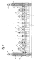
- a device carrier which can be raised and lowered here as a supporting beam 1 on both sides of column guides 2 with 3 electric spindles 4 with threaded spindles.
- the device carrier (support beam 1) serves to accommodate the transverse transport for the workpieces between the individual processing stations 5, such as turning and hammering machines or other non-cutting forming stations with feed units 6; the transport tongs 7 are used for this purpose, which cycle back and forth in a known manner and thus connect the stations 5.
- the intermediate station 8 for thread cutting and the turning station 9 are arranged on the support beam 1 so that it can be raised and lowered, while the drilling station 10 is arranged here, for example, in a stationary manner. In this way, maintenance work and tool changes at the processing stations when the support beam 1 is raised are considerably simplified and the risk of accidents and damage is reduced.
- Fig. 1 the inlet is still indicated at 11 and in Fig. 2 12 represents an intermediate storage for the workpieces.
- the column guide 2 with an electric motor 3 for the threaded spindle 4 for the lifting movement of the supporting beam 1 on one side is shown with a bearing block 13 and index pin 14 for fixing the position of the supporting beam 1 in its working position for carrying out the transverse transport.
- the column-guided support bracket 15 serves to raise and lower the support beam 1 in and out of the working position.
Landscapes
- Engineering & Computer Science (AREA)
- Mechanical Engineering (AREA)
- Multi-Process Working Machines And Systems (AREA)
- Turning (AREA)
- Heat Treatments In General, Especially Conveying And Cooling (AREA)
- Harvester Elements (AREA)
- Specific Conveyance Elements (AREA)
- Chain Conveyers (AREA)
- Replacement Of Web Rolls (AREA)
- Intermediate Stations On Conveyors (AREA)
Priority Applications (1)
| Application Number | Priority Date | Filing Date | Title |
|---|---|---|---|
| AT83106951T ATE20205T1 (de) | 1982-07-22 | 1983-07-15 | Quertransporteinrichtung mit vorrichtungstraeger fuer verkettete transferanlagen. |
Applications Claiming Priority (2)
| Application Number | Priority Date | Filing Date | Title |
|---|---|---|---|
| DE3227352 | 1982-07-22 | ||
| DE3227352A DE3227352C2 (de) | 1982-07-22 | 1982-07-22 | Transferanlage mit einer Transporteinrichtung zum Verbinden der einzelnen Bearbeitungsstationen |
Publications (3)
| Publication Number | Publication Date |
|---|---|
| EP0099556A2 EP0099556A2 (de) | 1984-02-01 |
| EP0099556A3 EP0099556A3 (en) | 1984-11-14 |
| EP0099556B1 true EP0099556B1 (de) | 1986-06-04 |
Family
ID=6169018
Family Applications (1)
| Application Number | Title | Priority Date | Filing Date |
|---|---|---|---|
| EP83106951A Expired EP0099556B1 (de) | 1982-07-22 | 1983-07-15 | Quertransporteinrichtung mit Vorrichtungsträger für verkettete Transferanlagen |
Country Status (4)
| Country | Link |
|---|---|
| EP (1) | EP0099556B1 (cs) |
| JP (1) | JPS5930649A (cs) |
| AT (1) | ATE20205T1 (cs) |
| DE (1) | DE3227352C2 (cs) |
Families Citing this family (2)
| Publication number | Priority date | Publication date | Assignee | Title |
|---|---|---|---|---|
| DE3918235C2 (de) * | 1989-06-05 | 1996-07-11 | Felss Geb | Anordnung für Transferlinien mit spanlosen und/oder spanabhebenden Bearbeitungsstationen |
| AT404687B (de) * | 1993-05-04 | 1999-01-25 | Sticht Fertigungstech Stiwa | Anlage zur bearbeitung und/oder montage von bauteilen |
Family Cites Families (5)
| Publication number | Priority date | Publication date | Assignee | Title |
|---|---|---|---|---|
| US2120966A (en) * | 1932-02-04 | 1938-06-21 | Max J Clark | Material handling apparatus for machine operations |
| US3061064A (en) * | 1960-02-25 | 1962-10-30 | Remington Arms Co Inc | Machine tool |
| US3075651A (en) * | 1961-03-07 | 1963-01-29 | Valen Mfg Co | Transfer device |
| US4139089A (en) * | 1977-08-15 | 1979-02-13 | Gulf & Western Manufacturing Company | Article feed mechanism |
| DE2849576A1 (de) * | 1978-11-15 | 1980-05-22 | Hans Lindemann | Werkzeugmaschinen-anordnung zum bearbeiten von aus stangenmaterial gewonnenen werkstuecke |
-
1982
- 1982-07-22 DE DE3227352A patent/DE3227352C2/de not_active Expired
-
1983
- 1983-07-15 EP EP83106951A patent/EP0099556B1/de not_active Expired
- 1983-07-15 AT AT83106951T patent/ATE20205T1/de not_active IP Right Cessation
- 1983-07-22 JP JP58134235A patent/JPS5930649A/ja active Granted
Also Published As
| Publication number | Publication date |
|---|---|
| DE3227352A1 (de) | 1984-01-26 |
| EP0099556A2 (de) | 1984-02-01 |
| JPS5930649A (ja) | 1984-02-18 |
| EP0099556A3 (en) | 1984-11-14 |
| JPS6327141B2 (cs) | 1988-06-01 |
| DE3227352C2 (de) | 1987-05-14 |
| ATE20205T1 (de) | 1986-06-15 |
Similar Documents
| Publication | Publication Date | Title |
|---|---|---|
| EP0296369B1 (de) | Vorrichtung zum automatischen Fördern von Spannrahmen oder dergleichen in Transferstrassen | |
| EP0995539B1 (de) | Bearbeitungsvorrichtung für Werkstücke | |
| DE3034107A1 (de) | Bohrmaschine fuer plattenfoermige oder scheibenfoermige werkstuecke | |
| DE2251012A1 (de) | Werkzeugaufnahmekopf fuer werkzeugmaschinen | |
| EP1321225A2 (de) | Bearbeitungsanlage mit mindestens einer Transportbahn und mehreren Bearbeitungsstationen | |
| EP0885686A1 (de) | Bearbeitungszelle | |
| DE1627042B2 (de) | Vorrichtung mit einem indexierbaren werkstuecktraeger und mit einem diesen foerdernden foerderring an einer ringtransfermaschine | |
| DE19800034C2 (de) | Werkzeugmaschine für Bearbeitungswerkzeuge aus der Gruppe Schleifkörper und Fräser | |
| EP0130309A1 (de) | Holzbearbeitungsmaschinen | |
| EP0480191B1 (de) | Vorrichtung zum Bearbeiten von Stangen | |
| EP1346788A2 (de) | Bearbeitungszentrum | |
| DE102005061586A1 (de) | Drehbank, und Bearbeitungssystem mit einer Drehbank | |
| DE1010800B (de) | Werkzeugmaschine mit aus seinen Fuehrungen ueberhaengend herausfahrbarem bzw. an einem Ausleger verfahrbarem Spindelstock | |
| DE3227352C2 (de) | Transferanlage mit einer Transporteinrichtung zum Verbinden der einzelnen Bearbeitungsstationen | |
| DE19911156C2 (de) | Drehmaschine zur Bearbeitung von wellenförmigen Werkstücken | |
| DE102005061587A1 (de) | Drehbank, und Bearbeitungssystem mit einer Drehbank | |
| DE60012279T2 (de) | Werkzeugwechselvorrichtung für Werkzeugmaschinen | |
| DE3240858A1 (de) | Vorrichtung fuer die bearbeitung eines metallischen werkstueckes durch stanzen oder praegen | |
| EP0338217B1 (de) | Hilfseinrichtung für die Bremsscheibenbearbeitung eines Eisenbahn-Radsatzes auf einer Radsatzdrehmaschine | |
| CH668020A5 (de) | Einrichtung zum automatischen werkstueckwechsel in numerisch gesteuerten mehroperationen-werkzeugmaschinen. | |
| DE102008005956B4 (de) | Bearbeitungszentrum mit Werkstückwechsler und Rüstplatz | |
| EP1218124B1 (de) | Vorrichtung zum umformen von länglichen elementen | |
| DE3414886C1 (de) | Werkzeugmaschine | |
| DE1166588B (de) | Radsatzdrehbank mit zweiseitigem Spindelstockantrieb | |
| EP0401718B1 (de) | Wechseleinrichtung für Werkzeugspindelträger an einer Bearbeitungsmaschine |
Legal Events
| Date | Code | Title | Description |
|---|---|---|---|
| PUAI | Public reference made under article 153(3) epc to a published international application that has entered the european phase |
Free format text: ORIGINAL CODE: 0009012 |
|
| AK | Designated contracting states |
Designated state(s): AT CH FR GB IT LI LU SE |
|
| PUAL | Search report despatched |
Free format text: ORIGINAL CODE: 0009013 |
|
| AK | Designated contracting states |
Designated state(s): AT CH FR GB IT LI LU SE |
|
| 17P | Request for examination filed |
Effective date: 19841201 |
|
| RAP1 | Party data changed (applicant data changed or rights of an application transferred) |
Owner name: GEBR. FELSS GMBH & CO. KG. |
|
| ITF | It: translation for a ep patent filed | ||
| GRAA | (expected) grant |
Free format text: ORIGINAL CODE: 0009210 |
|
| AK | Designated contracting states |
Kind code of ref document: B1 Designated state(s): AT CH FR GB IT LI LU SE |
|
| REF | Corresponds to: |
Ref document number: 20205 Country of ref document: AT Date of ref document: 19860615 Kind code of ref document: T |
|
| ET | Fr: translation filed | ||
| PLBE | No opposition filed within time limit |
Free format text: ORIGINAL CODE: 0009261 |
|
| STAA | Information on the status of an ep patent application or granted ep patent |
Free format text: STATUS: NO OPPOSITION FILED WITHIN TIME LIMIT |
|
| 26N | No opposition filed | ||
| ITTA | It: last paid annual fee | ||
| EPTA | Lu: last paid annual fee | ||
| EAL | Se: european patent in force in sweden |
Ref document number: 83106951.3 |
|
| REG | Reference to a national code |
Ref country code: GB Ref legal event code: IF02 |
|
| PGFP | Annual fee paid to national office [announced via postgrant information from national office to epo] |
Ref country code: GB Payment date: 20020621 Year of fee payment: 20 |
|
| PGFP | Annual fee paid to national office [announced via postgrant information from national office to epo] |
Ref country code: FR Payment date: 20020717 Year of fee payment: 20 |
|
| PGFP | Annual fee paid to national office [announced via postgrant information from national office to epo] |
Ref country code: AT Payment date: 20020722 Year of fee payment: 20 |
|
| PGFP | Annual fee paid to national office [announced via postgrant information from national office to epo] |
Ref country code: SE Payment date: 20020723 Year of fee payment: 20 Ref country code: LU Payment date: 20020723 Year of fee payment: 20 |
|
| PGFP | Annual fee paid to national office [announced via postgrant information from national office to epo] |
Ref country code: CH Payment date: 20020726 Year of fee payment: 20 |
|
| PG25 | Lapsed in a contracting state [announced via postgrant information from national office to epo] |
Ref country code: LI Free format text: LAPSE BECAUSE OF EXPIRATION OF PROTECTION Effective date: 20030714 Ref country code: GB Free format text: LAPSE BECAUSE OF EXPIRATION OF PROTECTION Effective date: 20030714 Ref country code: CH Free format text: LAPSE BECAUSE OF EXPIRATION OF PROTECTION Effective date: 20030714 |
|
| PG25 | Lapsed in a contracting state [announced via postgrant information from national office to epo] |
Ref country code: LU Free format text: LAPSE BECAUSE OF EXPIRATION OF PROTECTION Effective date: 20030715 Ref country code: AT Free format text: LAPSE BECAUSE OF EXPIRATION OF PROTECTION Effective date: 20030715 |
|
| REG | Reference to a national code |
Ref country code: GB Ref legal event code: PE20 |
|
| REG | Reference to a national code |
Ref country code: CH Ref legal event code: PL |
|
| EUG | Se: european patent has lapsed |