EP0099634A2 - Réacteur assurant le contact des phases multiples - Google Patents
Réacteur assurant le contact des phases multiples Download PDFInfo
- Publication number
- EP0099634A2 EP0099634A2 EP83303242A EP83303242A EP0099634A2 EP 0099634 A2 EP0099634 A2 EP 0099634A2 EP 83303242 A EP83303242 A EP 83303242A EP 83303242 A EP83303242 A EP 83303242A EP 0099634 A2 EP0099634 A2 EP 0099634A2
- Authority
- EP
- European Patent Office
- Prior art keywords
- vessel
- gas
- draft tube
- conical surface
- diameter
- Prior art date
- Legal status (The legal status is an assumption and is not a legal conclusion. Google has not performed a legal analysis and makes no representation as to the accuracy of the status listed.)
- Granted
Links
Images
Classifications
-
- C—CHEMISTRY; METALLURGY
- C12—BIOCHEMISTRY; BEER; SPIRITS; WINE; VINEGAR; MICROBIOLOGY; ENZYMOLOGY; MUTATION OR GENETIC ENGINEERING
- C12M—APPARATUS FOR ENZYMOLOGY OR MICROBIOLOGY; APPARATUS FOR CULTURING MICROORGANISMS FOR PRODUCING BIOMASS, FOR GROWING CELLS OR FOR OBTAINING FERMENTATION OR METABOLIC PRODUCTS, i.e. BIOREACTORS OR FERMENTERS
- C12M23/00—Constructional details, e.g. recesses, hinges
- C12M23/02—Form or structure of the vessel
-
- C—CHEMISTRY; METALLURGY
- C12—BIOCHEMISTRY; BEER; SPIRITS; WINE; VINEGAR; MICROBIOLOGY; ENZYMOLOGY; MUTATION OR GENETIC ENGINEERING
- C12M—APPARATUS FOR ENZYMOLOGY OR MICROBIOLOGY; APPARATUS FOR CULTURING MICROORGANISMS FOR PRODUCING BIOMASS, FOR GROWING CELLS OR FOR OBTAINING FERMENTATION OR METABOLIC PRODUCTS, i.e. BIOREACTORS OR FERMENTERS
- C12M27/00—Means for mixing, agitating or circulating fluids in the vessel
- C12M27/02—Stirrer or mobile mixing elements
-
- C—CHEMISTRY; METALLURGY
- C12—BIOCHEMISTRY; BEER; SPIRITS; WINE; VINEGAR; MICROBIOLOGY; ENZYMOLOGY; MUTATION OR GENETIC ENGINEERING
- C12M—APPARATUS FOR ENZYMOLOGY OR MICROBIOLOGY; APPARATUS FOR CULTURING MICROORGANISMS FOR PRODUCING BIOMASS, FOR GROWING CELLS OR FOR OBTAINING FERMENTATION OR METABOLIC PRODUCTS, i.e. BIOREACTORS OR FERMENTERS
- C12M27/00—Means for mixing, agitating or circulating fluids in the vessel
- C12M27/18—Flow directing inserts
- C12M27/24—Draft tube
-
- C—CHEMISTRY; METALLURGY
- C12—BIOCHEMISTRY; BEER; SPIRITS; WINE; VINEGAR; MICROBIOLOGY; ENZYMOLOGY; MUTATION OR GENETIC ENGINEERING
- C12M—APPARATUS FOR ENZYMOLOGY OR MICROBIOLOGY; APPARATUS FOR CULTURING MICROORGANISMS FOR PRODUCING BIOMASS, FOR GROWING CELLS OR FOR OBTAINING FERMENTATION OR METABOLIC PRODUCTS, i.e. BIOREACTORS OR FERMENTERS
- C12M29/00—Means for introduction, extraction or recirculation of materials, e.g. pumps
- C12M29/06—Nozzles; Sprayers; Spargers; Diffusers
Definitions
- the present invention relates to apparatus and method for carrying out multiphase contacting in liquids for the promotion of physical, chemical or biological changes, more particularly bioconversion and biotransformation processes, as in fermentation and enzymatic processes, utilizing such apparatus.
- Particulate solids such as, microbial, animal or plant cells or their components attached to artificial carriers, or nutrient substrates, are involved in many useful and potentially useful bioconversion or biotransformation processes.
- it is often essential to contact the solid particles with a liquid phase to permit biochemical reactions involving components contained in the solids and in the liquid phase to occur.
- a gas solute for example, oxygen
- the processes may need to be carried out under mild conditions of mixing and agitation in order to avoid deleterious effects, such as, cellular damage or excessive use of energy for mixing and/or aeration.
- an apparatus for effecting multiphase contacting between gas, solid and liquid phases comprising an upright vessel containing liquid medium and particulate material, a gas sparger to admit at least one gas to the liquid medium in the vessel, and circulation inducing means within the vessel to effect mild and uniform mixing and to ensure the absence of stagnant zones within the vessel and the avoidance of zones of high shear.
- the present invention also includes a method of effecting multiphase contacting using the apparatus.
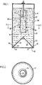
- an upright generally right-cylindrical reactor vessel 10 houses a liquid phase medium 12 which contains solid particulates 14.
- the solid particulates 14 may be any substance which contains one or more components capable of undergoing physical, chemical or biochemical reactions with components of the liquid medium 12. Such substances include solid cellulosic substrates, metal-bearing ores, cells of microbes, plants or animals, or artificially-immobilized enzymes.
- the liquid medium 12 may contain one or more components capable of undergoing chemical or biochemical reactions with components of the solid particulates 14.
- the liquid phase reaction medium for example, may comprise an aqueous nutrient medium for fermentation containing dissolved salts, sugars and other components commonly used in fermentation media.
- the reactor vessel 10 may be of any convenient dimension and usually has a height-to-diameter ratio in the range of about 1:1 to about 4:1, preferably about 3:1.
- a gas sparger 16 for the introduction of at least one gas takes the form of an array of orifices 17 located around the outer perimeter of the base 18 of the reactor vessel 10.
- the orifices 17 may have any convenient diameter, generally from about 0.05 to about 1 cm, typically about 0.3 cm, and may be spaced apart any convenient distance, usually about 1 to about 10 cm, typically about 1.25 cm.
- Any other convenient form of gas sparger 16, such as, a perforated hollow ring, may be provided. Additional aeration and/or agitation may be effected, if desired, by the use of two or more such gas spargers 16.
- An inverted cone 20 forms the bottom wall 18 of the reactor vessel 10 and its perimeter is spaced from the upright wall 22 of the reactor 10, so that the orifices 17 of the gas sparger 16 communicate with the crevice 23 which is formed by the bottom and side walls 18, 22 of the reactor 10 and the inverted cone 20.
- the inverted cone 20 may have any convenient conical angle usually about 30° to about 90°. In the case of non-sticking and/or non-settling particulates, the inverted cone 20 may be omitted and a planar bottom wall 18 utilized.
- the gas sparger 16 injects gas bubbles 24 through the multiple orifices 17 into the crevice 23 and thereby into the liquid medium 12.
- a right cylindrical draft tube 26 is arranged coaxially with the reactor vessel 10 and is located within the liquid medium spaced upwardly from the inverted cone 20, inwardly from the reactor side wall 22 and downwardly from the surface of the liquid medium 12 in the reactor 10.
- the draft tube 26 has a diameter such that the ratio of the diameter of the vessel 10 to the diameter of draft tube 26 is usually about 2:1 to about 5:1, preferably about 4:1.
- the draft tube 26 may be spaced upwardly from the inverted cone 20 and downwardly from the upper level of liquid medium 12 any convenient distance, typically about the same distance. Generally, the distance is about 5 to about 10 cm.
- the draft tube 26 separates the interior of the reactor vessel 10 into concentric flow channels 28 and 30 through which the reaction medium 12 flows in opposite directions.
- the flow channels 26 and 28 are formed even if the draft tube is omitted.
- the draft tube 26, however, is usually used to provide a clear demarkation between the flow channels and prevents cross-mixing.
- An axial downflow-type impeller 32 for example, a propeller, may be located within the flow channel 30 to assist in the suppression of foam formation and a supplementary ring sparger 34 may be located between the outer wall of the draft tube 26 and the inside wall of the reactor vessel 10 to increase the gas flow to the liquid medium 12.
- a heat exchanger (not shown) also may be associated with the draft tube 26 to enable the liquid medium 12 to be heated or cooled, as required.
- a gas usually air where an aerobic reaction is required, or an inert gas where an anaerobic reaction is required, is fed into the reactor vessel 10 through the gas sparger 16, thereby forming the gas bubbles 34 in the crevices 23.
- the gas bubbles 24 rise in the crevices 23, thereby clearing and cleaning the crevices 23 of any particulate solids which may settle therein.
- the gas bubbles pass into the outer annular flow channel 28 and create a hydrostatic pressure difference between the contents of the annular flow channel 28 and the inner flow channel 30.
- a suction effect is created within the inner flow channel 30, thereby causing the reaction medium 12 in the outer annular channel 28 to flow upwardly until it clears the upper edge of the draft tube 26, to flow downwardly through the inner channel 30 until it clears the bottom edge of the draft tube 26, and then to flow once again into the annular channel 28.
- This circulatory flow motion of the liquid reaction medium 12, which may carry within it the suspended solids 14 and gas bubbles 24 is illustrated by arrows in Figure 1.
- the suction effect created within the inner flow channel 30 may be enhanced by the action of the impeller 32.
- the impeller 32 also assists in liquid recirculation within the reactor 10. More than one such impeller 32 may be utilized, depending on the vertical height of the vessel and the intensity of the recirculation required.
- the suction effect in the inner flow channel 30 carries any undesirable foam which may form on the surface of the reaction medium 12 in the reactor 10 into the bulk liquid below the surface where the foam is destroyed by re-dissolution and/or bubble coalescence.
- Additional aeration and/or agitation may also be effected, if desired; by the utilization of one or more supplementary ring spargers 34.
- the orifices of this sparger 34 are arranged to eject gas radially outwardly thereof so that small preformed bubbles are readily detached by the upward fluid flow in the channel 28.
- the reactor vessel 10 may have a square or rectangular cross section, while the draft tube 26 may be replaced by a conduit of square or rectangular cross section.
- the draft tube 26 may be formed by two flat baffle plates which extend between the sides of the vessel.
- the inverted insert 20 is illustrated as having a conical shape, but may have a pyramid shape or a wedge shape.
- the insert 20 may be integrally formed with the reactor vessel 10 to constitute the bottom wall 18, rather than as the separate member illustrated.
- the gas sparger 34 generally follows the geometrical shape of the draft tube 26.
- the reactor vessel 10 may be used for carrying out a wide variety of bioconversion and biotransformation processes in a manner which overcomes the prior art problems of mechanically stirred vessels.
- the entry of the gas to the reactor vessel 10 and the thorough and uniform mixing of the solid phase and liquid phase within the reactor vessel 10 prevents the accumulation of particulate solids in unmixed stagnant zones and the growth of cellular biomass in crevices and other stagnant zones or poorly mixed regions of the reactor vessel 10.
- the induced suction in the channel 30 eliminates foam accumulation on the surface of the liquid medium 12 and produces only low shear forces on biological cells, so that damage or destruction of the cells by shear forces is eliminated. In this way, considerably enhanced microbial growth can be achieved using this invention.
- the bioconversion or biotransformation process which is effected using the apparatus of the invention may be a fermentation process using any desired organism, for example, aerobic fermentation using Chaetomium cellulolyticum (American Type Culture Collection, Rockville, Maryland, Accession No. 32319).
- the particulate solid phase material 14 usually is a cellulosic-containing material to provide carbon nutrient for the organism growth.
- the cellulosic-containing material may be any convenient cellulosic material, such as, wheat straw, corn stover or Kraft paper pulp mill clarifier waste sludge.
- the cellulosic material usually is in the form of particulate solids of up to about 2 cm particle mesh size.
- the cellulosic material may be provided in any convenient concentration for carrying out the fermentation, usually up to about 5% w/v (weight per unit volume).
- the flow rate of gas through the sparger 16 into the reactor 10 may be any convenient value, depending on the process which is being effected in the reactor vessel 10. Usually, the gas flow rate is in the range of up to about 2 volumes of gas per volume of liquid medium per minute.
- Gas-liquid mass transfer is achieved in the vessel 10 at rates comparable to conventional high shear mechanically-stirred devices. Further, the efficiency of liquid mixing within the vessel 10 is superior to conventional low-shear pneumatically-stirred devices.
- microbial biomass in the form of the fungal organism Chaetomium cellulolyticum
- microbial biomass in the form of the fungal organism Chaetomium cellulolyticum
- an aerated aqueous nutrient medium containing 1% particulate solids in the form of chemically pretreated pieces of wheat straw (average mesh size of 2 mm) as the sole carbon source for the fermentation process.
- the process proceeded with virtually no interference from microbial growth attachments to the vessel walls or bottom or settling out of particulate solids within the device.
- the rate of oxygen transfer from sparged air bubbles into the liquid phase of a typical fermentation medium was measured as an overall mass transfer coefficient of about 120 reciprocal hours. It was found that the oxygen transfer efficiency in terms of power requirements per unit volume of vessel contents was comparable to that obtained in a conventional high-shear mechanically stirred tank fermentor device of the same size and for the same aeration conditions.
- the volume of air bubbles retained in the liquid phase of a typical fermentation medium was measured as 12% volume of gas per volume of liquid. It was found that a similar gas-bubble retention was obtained in a conventional low shear bubble column of the same size and for the same aeration conditions.
- the present invention provides novel apparatus having improved operating parameters in physical, chemical or biochemical reactions, including bioconversion and biotransformation processes. Modifications are possible within the scope of this invention.
Landscapes
- Health & Medical Sciences (AREA)
- Organic Chemistry (AREA)
- Life Sciences & Earth Sciences (AREA)
- Engineering & Computer Science (AREA)
- Bioinformatics & Cheminformatics (AREA)
- Chemical & Material Sciences (AREA)
- Zoology (AREA)
- Wood Science & Technology (AREA)
- Sustainable Development (AREA)
- Microbiology (AREA)
- Biotechnology (AREA)
- Biomedical Technology (AREA)
- Biochemistry (AREA)
- General Engineering & Computer Science (AREA)
- General Health & Medical Sciences (AREA)
- Genetics & Genomics (AREA)
- Clinical Laboratory Science (AREA)
- Apparatus Associated With Microorganisms And Enzymes (AREA)
Applications Claiming Priority (4)
| Application Number | Priority Date | Filing Date | Title |
|---|---|---|---|
| US38605282A | 1982-06-07 | 1982-06-07 | |
| US386052 | 1982-06-07 | ||
| GB8216858 | 1982-06-10 | ||
| GB8216858 | 1982-06-10 |
Publications (3)
| Publication Number | Publication Date |
|---|---|
| EP0099634A2 true EP0099634A2 (fr) | 1984-02-01 |
| EP0099634A3 EP0099634A3 (en) | 1984-06-27 |
| EP0099634B1 EP0099634B1 (fr) | 1987-01-07 |
Family
ID=26283072
Family Applications (1)
| Application Number | Title | Priority Date | Filing Date |
|---|---|---|---|
| EP19830303242 Expired EP0099634B1 (fr) | 1982-06-07 | 1983-06-06 | Réacteur assurant le contact des phases multiples |
Country Status (2)
| Country | Link |
|---|---|
| EP (1) | EP0099634B1 (fr) |
| DE (1) | DE3368953D1 (fr) |
Cited By (9)
| Publication number | Priority date | Publication date | Assignee | Title |
|---|---|---|---|---|
| EP0111885A1 (fr) * | 1982-12-18 | 1984-06-27 | Hoechst Aktiengesellschaft | Réactions à l'aide de biocatalyseurs immobilisés |
| GB2202549A (en) * | 1987-03-20 | 1988-09-28 | Philip John Whitney | Foldable fermenter |
| US4904601A (en) * | 1988-02-16 | 1990-02-27 | Snow Brand Milk Products Co., Ltd. | Cell culture tank |
| CN108048319A (zh) * | 2017-12-22 | 2018-05-18 | 广州汉腾生物科技有限公司 | 细胞培养反应器 |
| WO2021069353A1 (fr) | 2019-10-09 | 2021-04-15 | Boehringer Ingelheim International Gmbh | Bioréacteur ou fermenteur pour la culture de cellules ou de micro-organismes en suspension à l'échelle industrielle |
| WO2022073783A1 (fr) * | 2020-10-08 | 2022-04-14 | Global Life Sciences Solutions Usa Llc | Système de biotraitement et appareil pour réduire le cisaillement cellulaire dans un système de biotraitement |
| CN115386479A (zh) * | 2022-10-11 | 2022-11-25 | 浙江工业大学 | 一种v型槽振荡式生物反应器 |
| EP4400575A1 (fr) * | 2023-01-13 | 2024-07-17 | MTM Anlagenbau GmbH | Installation de prétraitement de matières premières solides pour la production de biogaz, installation de biogaz et procédé de production de biogaz |
| EP4467232A1 (fr) * | 2023-05-26 | 2024-11-27 | Sartorius Stedim Biotech GmbH | Dispositif d'aération pour une installation de biotraitement |
Family Cites Families (5)
| Publication number | Priority date | Publication date | Assignee | Title |
|---|---|---|---|---|
| FR958486A (fr) * | 1950-03-10 | |||
| FR1373751A (fr) * | 1963-08-12 | 1964-10-02 | Procédé et dispositif d'agitation avec circulation méthodique de masses liquides par insufflation de gaz | |
| CH472496A (de) * | 1966-03-16 | 1969-05-15 | Process Engineering Co | Einrichtung zur Durchführung mikrobiologischer Fermentationsverfahren |
| CH578887A5 (fr) * | 1973-08-30 | 1976-08-31 | Mueller Hans Maennedorf | |
| US4036699A (en) * | 1976-02-02 | 1977-07-19 | Phillips Petroleum Company | Fermentation apparatus and method |
-
1983
- 1983-06-06 DE DE8383303242T patent/DE3368953D1/de not_active Expired
- 1983-06-06 EP EP19830303242 patent/EP0099634B1/fr not_active Expired
Cited By (12)
| Publication number | Priority date | Publication date | Assignee | Title |
|---|---|---|---|---|
| EP0111885A1 (fr) * | 1982-12-18 | 1984-06-27 | Hoechst Aktiengesellschaft | Réactions à l'aide de biocatalyseurs immobilisés |
| GB2202549A (en) * | 1987-03-20 | 1988-09-28 | Philip John Whitney | Foldable fermenter |
| US4904601A (en) * | 1988-02-16 | 1990-02-27 | Snow Brand Milk Products Co., Ltd. | Cell culture tank |
| CN108048319A (zh) * | 2017-12-22 | 2018-05-18 | 广州汉腾生物科技有限公司 | 细胞培养反应器 |
| WO2021069353A1 (fr) | 2019-10-09 | 2021-04-15 | Boehringer Ingelheim International Gmbh | Bioréacteur ou fermenteur pour la culture de cellules ou de micro-organismes en suspension à l'échelle industrielle |
| AU2020362911B2 (en) * | 2019-10-09 | 2025-07-24 | Boehringer Ingelheim International Gmbh | Bioreactor or fermenter for the culturing of cells or microorganisms in suspension in industrial scale |
| US12371651B2 (en) | 2019-10-09 | 2025-07-29 | Boehringer Ingelheim International Gmbh | Bioreactor or fermenter for the culturing of cells or microorganisms in suspension in industrial scale |
| WO2022073783A1 (fr) * | 2020-10-08 | 2022-04-14 | Global Life Sciences Solutions Usa Llc | Système de biotraitement et appareil pour réduire le cisaillement cellulaire dans un système de biotraitement |
| CN115386479A (zh) * | 2022-10-11 | 2022-11-25 | 浙江工业大学 | 一种v型槽振荡式生物反应器 |
| EP4400575A1 (fr) * | 2023-01-13 | 2024-07-17 | MTM Anlagenbau GmbH | Installation de prétraitement de matières premières solides pour la production de biogaz, installation de biogaz et procédé de production de biogaz |
| EP4467232A1 (fr) * | 2023-05-26 | 2024-11-27 | Sartorius Stedim Biotech GmbH | Dispositif d'aération pour une installation de biotraitement |
| WO2024245760A1 (fr) * | 2023-05-26 | 2024-12-05 | Sartorius Stedim Biotech Gmbh | Dispositif d'aération pour une installation de biotraitement |
Also Published As
| Publication number | Publication date |
|---|---|
| DE3368953D1 (en) | 1987-02-12 |
| EP0099634A3 (en) | 1984-06-27 |
| EP0099634B1 (fr) | 1987-01-07 |
Similar Documents
| Publication | Publication Date | Title |
|---|---|---|
| US4643972A (en) | Method and apparatus for multiphase contacting between gas, solid and liquid phases | |
| US4263143A (en) | Process and apparatus for dispersing gas in a liquid | |
| EP0422149B1 (fr) | Oxygenateur statique pour la culture de cellules animales en suspension | |
| EP0418187B1 (fr) | Procédé et appareil pour effectuer une fermentation | |
| AU2020317552B2 (en) | Bioreactors for growing micro-organisms | |
| EP0099634B1 (fr) | Réacteur assurant le contact des phases multiples | |
| Träger et al. | Comparison of airlift and stirred reactors for fermentation with Aspergillus niger | |
| KR102822652B1 (ko) | 동적 스파저를 갖는 반응기 | |
| GB1575417A (en) | Processes for promoting interactions in liquid media | |
| US20100291621A1 (en) | Anaerobic process | |
| US5248485A (en) | Method for mixing liquid, solids and gas and for simultaneously separating gas or gas and solids from the liquid | |
| RU2236451C1 (ru) | Аппарат для аэробной жидкофазной ферментации | |
| KR20210099619A (ko) | 미생물 성장을 위한 바이오리액터 | |
| CN212247023U (zh) | 一种发酵罐进出料及搅拌器的布置系统 | |
| WO2019162971A1 (fr) | Système d'aération amélioré pour bioréacteur, fermenteur et récipient de traitement | |
| US5045470A (en) | Device for submerged culture of tissue cells | |
| US4378436A (en) | Process and device for improving the quality of mixing of liquid especially viscous media | |
| Vicente et al. | Hydrodynamic performance of a three-phase airlift bioreactor with an enlarged degassing zone | |
| EP0031258B1 (fr) | Colonne à bulles avec dispositif d'aspiration | |
| CN112481101A (zh) | 一种有氧发酵系统及工艺 | |
| US4717669A (en) | Centrifugal film fermenter | |
| JPH0343070A (ja) | 固相生体触媒を伴なう生体触媒過程の実施のための装置 | |
| RU2739528C1 (ru) | Ферментер для культивирования биомассы метанокисляющих микроорганизмов Methylococcus capsulatus | |
| WO2023023857A1 (fr) | Procédé et système de culture d'organismes filamenteux | |
| KR850003238Y1 (ko) | 기포탑용 통풍장치 |
Legal Events
| Date | Code | Title | Description |
|---|---|---|---|
| PUAI | Public reference made under article 153(3) epc to a published international application that has entered the european phase |
Free format text: ORIGINAL CODE: 0009012 |
|
| AK | Designated contracting states |
Designated state(s): DE FR GB IT |
|
| PUAL | Search report despatched |
Free format text: ORIGINAL CODE: 0009013 |
|
| AK | Designated contracting states |
Designated state(s): DE FR GB IT |
|
| 17P | Request for examination filed |
Effective date: 19840830 |
|
| GRAA | (expected) grant |
Free format text: ORIGINAL CODE: 0009210 |
|
| AK | Designated contracting states |
Kind code of ref document: B1 Designated state(s): DE FR GB IT |
|
| ITF | It: translation for a ep patent filed | ||
| REF | Corresponds to: |
Ref document number: 3368953 Country of ref document: DE Date of ref document: 19870212 |
|
| ET | Fr: translation filed | ||
| PLBE | No opposition filed within time limit |
Free format text: ORIGINAL CODE: 0009261 |
|
| STAA | Information on the status of an ep patent application or granted ep patent |
Free format text: STATUS: NO OPPOSITION FILED WITHIN TIME LIMIT |
|
| 26N | No opposition filed | ||
| PGFP | Annual fee paid to national office [announced via postgrant information from national office to epo] |
Ref country code: FR Payment date: 19890630 Year of fee payment: 7 |
|
| PG25 | Lapsed in a contracting state [announced via postgrant information from national office to epo] |
Ref country code: DE Effective date: 19900301 |
|
| PGFP | Annual fee paid to national office [announced via postgrant information from national office to epo] |
Ref country code: GB Payment date: 19900424 Year of fee payment: 8 |
|
| PG25 | Lapsed in a contracting state [announced via postgrant information from national office to epo] |
Ref country code: FR Effective date: 19910228 |
|
| REG | Reference to a national code |
Ref country code: FR Ref legal event code: ST |
|
| PG25 | Lapsed in a contracting state [announced via postgrant information from national office to epo] |
Ref country code: GB Effective date: 19910606 |
|
| GBPC | Gb: european patent ceased through non-payment of renewal fee |