EP0099678B1 - Slat feeding apparatus for assembling machine - Google Patents
Slat feeding apparatus for assembling machine Download PDFInfo
- Publication number
- EP0099678B1 EP0099678B1 EP83303819A EP83303819A EP0099678B1 EP 0099678 B1 EP0099678 B1 EP 0099678B1 EP 83303819 A EP83303819 A EP 83303819A EP 83303819 A EP83303819 A EP 83303819A EP 0099678 B1 EP0099678 B1 EP 0099678B1
- Authority
- EP
- European Patent Office
- Prior art keywords
- slats
- slat
- cradle
- headstock
- base
- Prior art date
- Legal status (The legal status is an assumption and is not a legal conclusion. Google has not performed a legal analysis and makes no representation as to the accuracy of the status listed.)
- Expired
Links
- 230000010006 flight Effects 0.000 claims description 3
- 230000000694 effects Effects 0.000 description 4
- 238000004519 manufacturing process Methods 0.000 description 4
- 230000000630 rising effect Effects 0.000 description 2
- 238000013459 approach Methods 0.000 description 1
- 230000006835 compression Effects 0.000 description 1
- 238000007906 compression Methods 0.000 description 1
- 238000010276 construction Methods 0.000 description 1
- 230000007812 deficiency Effects 0.000 description 1
- 230000033001 locomotion Effects 0.000 description 1
Images


Classifications
-
- E—FIXED CONSTRUCTIONS
- E06—DOORS, WINDOWS, SHUTTERS, OR ROLLER BLINDS IN GENERAL; LADDERS
- E06B—FIXED OR MOVABLE CLOSURES FOR OPENINGS IN BUILDINGS, VEHICLES, FENCES OR LIKE ENCLOSURES IN GENERAL, e.g. DOORS, WINDOWS, BLINDS, GATES
- E06B9/00—Screening or protective devices for wall or similar openings, with or without operating or securing mechanisms; Closures of similar construction
- E06B9/24—Screens or other constructions affording protection against light, especially against sunshine; Similar screens for privacy or appearance; Slat blinds
- E06B9/26—Lamellar or like blinds, e.g. venetian blinds
- E06B9/266—Devices or accessories for making or mounting lamellar blinds or parts thereof
-
- Y—GENERAL TAGGING OF NEW TECHNOLOGICAL DEVELOPMENTS; GENERAL TAGGING OF CROSS-SECTIONAL TECHNOLOGIES SPANNING OVER SEVERAL SECTIONS OF THE IPC; TECHNICAL SUBJECTS COVERED BY FORMER USPC CROSS-REFERENCE ART COLLECTIONS [XRACs] AND DIGESTS
- Y10—TECHNICAL SUBJECTS COVERED BY FORMER USPC
- Y10T—TECHNICAL SUBJECTS COVERED BY FORMER US CLASSIFICATION
- Y10T29/00—Metal working
- Y10T29/39—Venetian blind assembling
Definitions
- the present invention relates to a slat feeding apparatus for an assembly machine for assembling slats and ladder cords to form a venetian blind.
- British Patent Specification 1562289 discloses a machine for the production of venetian blind slats and for assembling them in relation to the ladder cords therefor.
- This machine includes a production unit by which slats are formed from reeled stock, and a slat/ladder cord assembly station into which the formed slats are fed, one at a time, for endwise advancement through the ladder cords. This is followed by the stacking of the slats together with the ladder cords in an assembled venetian blind array.
- apparatus for assembling slats in the ladder cords of venetian blinds comprising
- Such an apparatus can be very compact and simple, but effective in feeding in the fully formed slats, one at a time from a stack thereof into the infeed end of the assembly station.
- the means on the cradle for picking up the slats comprises:-
- means are provided to break the vacuum in the suction cup.
- These means may comprise a valve within the suction cup and a passage closed by the valve, the passage communicating with the exterior and means to lower the valve stem so that air can enter the suction cup via the valve guide.
- the means within the headstock comprise a pair of endless belts having working flights able to receive a slat therebetween and to direct it into the assembly station. If the cradle is mounted below the assembly station then slats may pass around a roller so that the slats can be the right way up. By having the slats mounted upside down in the cradle, this has the advantage that when the suction cup picks up a slat it will be acting on the concave side of the slat and will tend to flatten the slat at the point of contact of the suction cup.
- the stop block has a camming face which confronts the leading end edges of the slats in the cradle and this is stepped to relieve contact between the leading end edges as they travel from the cradle to the headstock.
- the cradle is swing-mounted on the base and the drive means comprise a linear motor.
- a machine base 9 has a headstock 10 upstanding at one end.
- This head-stock has a slat-ladder cord assembly station 11 extending from it in cantilever fashion to overlie the base 9.
- Station 11 is substantially of known kind (as indicated) in that it is adapted to receive longitudinally disposed slats by way of its infeed end 12.
- the arriving slats take up a stacking position as indicated at 13 and in so doing they extend through a selected number of work stations 14 where they are threaded through and engage with the ladder cords 15 drawn up from a ladder cord magazine 16.
- Station 11 may include the usual control means such as an adjustable photoelectric stop 17 which, by engagement with the arriving slat cord, initiates the next slat infeed cycle.
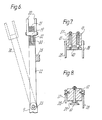
- a slat magazine cradle 18 mounted below the assembly station 11 includes a spinal bar 19 carrying pairs of upstanding fingers 20 to form a channel-like receiver for a stack of fully formed slats 21.
- the bar 19 could be stationary but is preferably mounted on a plurality of radius rods 22, hinged on the base 9 at 23, so that the cradle may be swung away from the position which is shown in full lines in Figure 6 to a second position shown in dotted lines in Figure 6 for assisting in the charging of the cradle with a fresh supply of slats.
- the cradle may be located and held in its work position by a magnetic catch 25 or otherwise.
- a bottom of the stack slat 28 is shown abutted against the face 27.
- Another slat 29 which is shown in the course of being lifted from the cradle is similarly abutted against the face 27.
- a line 30 indicating the maximum stack height which is possible, and at 31 a further slat is shown, raised from the stack and in the course of being presented to the headstock.
- the spinal bar 19 also carries a linear motor 32 having its armature 33 ( Figure 6) coupled at 34 with one end of a draglink 35 of which the other end is pivoted at 36 to a slat elevator block 37.
- the block 37 is swing-mounted on the block 26, so as to ensure that, during translation of the block 37 between its top position and its bottom position indicated at 37A, the block remains similarly oriented relative to the horizontal.
- the block 37 carries a suction cup 39 and a stripper block 40 which is springloaded as shown at 41 ( Figure 7).
- Figure 2 shows the suction cup 39 which is provided with a passage 60 which can be closed by a valve 61 carried at the lower end of a valve stem 62 which is surrounded, at the top, by a compression spring 63 engaged on a disc 64, so that the valve 61 is urged upwardly to close the passage 60.
- the upper end of the valve stem 62 can be engaged by a pusher 65 mounted on an arm 66 by means of a screw and wingnut 67.
- the pusher 65 can thus disengage the upper surface of the valve 61 on the interior of the suction cup so that the vacuum is released via the passage 60.
- linear motor 32 When a slat is to be picked up from the top of the stack in the cradle 18, linear motor 32 is operated to lower block 37 into a position such as that shown in 37A or that indicated by dotted lines 42 as the height of the stack permits. In doing this, block 40 cushions the impact with which the cup 39 takes a hold on the top slat. Reverse operation of the motor 32 in the direction of the arrow in Figure 2 lifts the slat towards the top position, as shown by slat 31 where the leading end 43 of the elevated slat is positioned for seizure and propulsion to the assembly station 11.
- the block 37 travels along an arc 44, and therefore the leading end of the slat which is rising, for example, from the position of slat 28, will follow a locus 45 of the same radius so that it is desirable for the caming face 27 to be inside the locus 45 (as shown), so that the raised slats are less likely to fall short of the top position they are to occupy in order to be seized as will be described later.
- the slats are relatively flexible and, therefore, when one is lifted in the manner shown by the slat 31, it bends, and so its trailing end continues to bear on the top of the stack.
Landscapes
- Engineering & Computer Science (AREA)
- Structural Engineering (AREA)
- Architecture (AREA)
- Civil Engineering (AREA)
- Blinds (AREA)
Applications Claiming Priority (2)
| Application Number | Priority Date | Filing Date | Title |
|---|---|---|---|
| GB08220688A GB2124283B (en) | 1982-07-16 | 1982-07-16 | Slat feeding apparatus for venetian blind assembling machine |
| GB8220688 | 1982-07-16 |
Publications (3)
| Publication Number | Publication Date |
|---|---|
| EP0099678A2 EP0099678A2 (en) | 1984-02-01 |
| EP0099678A3 EP0099678A3 (en) | 1984-05-23 |
| EP0099678B1 true EP0099678B1 (en) | 1985-10-09 |
Family
ID=10531727
Family Applications (1)
| Application Number | Title | Priority Date | Filing Date |
|---|---|---|---|
| EP83303819A Expired EP0099678B1 (en) | 1982-07-16 | 1983-06-30 | Slat feeding apparatus for assembling machine |
Country Status (9)
| Country | Link |
|---|---|
| US (1) | US4538330A (da) |
| EP (1) | EP0099678B1 (da) |
| JP (1) | JPS5931389A (da) |
| AU (1) | AU9102382A (da) |
| CA (1) | CA1209794A (da) |
| DE (1) | DE3360980D1 (da) |
| DK (1) | DK325283A (da) |
| GB (1) | GB2124283B (da) |
| NZ (1) | NZ202700A (da) |
Families Citing this family (5)
| Publication number | Priority date | Publication date | Assignee | Title |
|---|---|---|---|---|
| GB2201710B (en) * | 1987-02-27 | 1990-10-17 | Hunter Douglas Ind Bv | Apparatus for feeding rigid spacers into travellers for a vertical blind |
| EP0295346B1 (en) * | 1987-06-18 | 1991-05-15 | Hunter Douglas Industries B.V. | A method and apparatus for mechanically assembling a venetian blind |
| JPH0641675Y2 (ja) * | 1988-12-29 | 1994-11-02 | 隆 成富 | スカム掻寄機 |
| AUPP301698A0 (en) * | 1998-04-15 | 1998-05-07 | Modra, Christopher Max | Wood venetian cut punch and ladder machine |
| CN118438158B (zh) * | 2024-05-31 | 2024-10-22 | 山东槿仕佳新材料科技有限公司 | 一种百叶窗叶片的绳带自动排列装配装置 |
Family Cites Families (10)
| Publication number | Priority date | Publication date | Assignee | Title |
|---|---|---|---|---|
| US2769223A (en) * | 1951-07-18 | 1956-11-06 | Harry S Rosenbaum | Venetian blind assembly machine |
| US3140867A (en) * | 1962-11-19 | 1964-07-14 | Herman L Cole | Adjustable feeder shoe for vertical printing presses |
| DE1195772B (de) * | 1963-07-19 | 1965-07-01 | Winkler Richard | Vorrichtung zum Vereinzeln und Fortfuehren von biegsamen, duennen Gegenstaenden von der Unter-seite eines Stapels |
| US3715118A (en) * | 1970-12-03 | 1973-02-06 | Jeddeloh Bros Sweed Mills Inc | Sheet separator and feeder assembly |
| CH565697A5 (da) * | 1973-02-28 | 1975-08-29 | Bobst Fils Sa J | |
| US4002332A (en) * | 1975-04-09 | 1977-01-11 | Acme Steel Door Corporation | Automatic feed mechanism for power brake or the like |
| DE2535453C2 (de) * | 1975-08-08 | 1986-12-11 | Hunter Douglas Industries B.V., Rotterdam | Vorrichtung zum Fertigstellen von Lamellenjalousien |
| DE2637218C2 (de) * | 1976-08-18 | 1980-10-02 | Georg Spiess Gmbh, 8906 Gersthofen | Bogenanleger |
| US4189136A (en) * | 1977-08-01 | 1980-02-19 | Strong-Robinette Bag Company, Inc. | Automatic bag tube feeder |
| JPS5825481Y2 (ja) * | 1978-07-27 | 1983-06-01 | ロ−レルバンクマシン株式会社 | 紙葉類計数機における吸引頭の先端部構造 |
-
1982
- 1982-07-16 GB GB08220688A patent/GB2124283B/en not_active Expired
- 1982-12-01 AU AU91023/82A patent/AU9102382A/en not_active Abandoned
- 1982-12-13 NZ NZ202700A patent/NZ202700A/en unknown
-
1983
- 1983-06-16 US US06/504,975 patent/US4538330A/en not_active Expired - Fee Related
- 1983-06-30 EP EP83303819A patent/EP0099678B1/en not_active Expired
- 1983-06-30 DE DE8383303819T patent/DE3360980D1/de not_active Expired
- 1983-07-14 DK DK325283A patent/DK325283A/da not_active Application Discontinuation
- 1983-07-15 CA CA000432564A patent/CA1209794A/en not_active Expired
- 1983-07-15 JP JP58129287A patent/JPS5931389A/ja active Pending
Also Published As
| Publication number | Publication date |
|---|---|
| DK325283A (da) | 1984-01-17 |
| JPS5931389A (ja) | 1984-02-20 |
| EP0099678A3 (en) | 1984-05-23 |
| GB2124283B (en) | 1987-04-23 |
| GB2124283A (en) | 1984-02-15 |
| EP0099678A2 (en) | 1984-02-01 |
| NZ202700A (en) | 1985-11-08 |
| CA1209794A (en) | 1986-08-19 |
| DE3360980D1 (en) | 1985-11-14 |
| DK325283D0 (da) | 1983-07-14 |
| AU9102382A (en) | 1984-01-19 |
| US4538330A (en) | 1985-09-03 |
Similar Documents
| Publication | Publication Date | Title |
|---|---|---|
| US6021887A (en) | Battery plate feeding and handling apparatus | |
| JP2879286B2 (ja) | 枚葉紙、本等のパックのパレット載置方法とその機器 | |
| US4143871A (en) | Facing ply separator | |
| JPS6411538B2 (da) | ||
| JPS6351223A (ja) | 包装機械に用紙を送る搬送装置 | |
| US5454687A (en) | High speed sorter/stacker | |
| EP1637237B1 (en) | Battery plate feeding and handling apparatus | |
| CN112009028A (zh) | 手提扣自动扣压设备 | |
| US4283047A (en) | Facing ply separator | |
| US4538330A (en) | Venetian blind assembly apparatus | |
| US6024533A (en) | Battery plate feeding and handling apparatus | |
| EP0166253B1 (en) | Device for accommodating cash enclosing envelopes | |
| JPH06127672A (ja) | トレイの移送方法とその装置 | |
| US4943207A (en) | Apparatus for denesting and feeding cartons to a conveyor | |
| CN212922135U (zh) | 一种纸管传送与捆扎装置 | |
| EP0259542B1 (en) | Sorting apparatus | |
| HU189618B (en) | Apparatus for continuous producing corrugated paper band | |
| US4047622A (en) | Pallet feeding apparatus | |
| US4331415A (en) | Automatic bundle forming apparatus | |
| US4867632A (en) | Apparatus for denesting and feeding cartons to a conveyor | |
| JP3494316B2 (ja) | 長尺物仕分け装置 | |
| JPH0767928B2 (ja) | 包装袋体の耳部折り曲げ装置 | |
| CN110833687B (zh) | 麻将机及其拾牌搬运系统、上牌组件、上牌方法和麻将牌整理方法 | |
| US4784559A (en) | Apparatus for subdividing piles of superimposed stacks of paper sheets and the like | |
| JP3614911B2 (ja) | 紙葉類処理装置および紙葉類処理方法 |
Legal Events
| Date | Code | Title | Description |
|---|---|---|---|
| PUAI | Public reference made under article 153(3) epc to a published international application that has entered the european phase |
Free format text: ORIGINAL CODE: 0009012 |
|
| AK | Designated contracting states |
Designated state(s): DE SE |
|
| PUAL | Search report despatched |
Free format text: ORIGINAL CODE: 0009013 |
|
| AK | Designated contracting states |
Designated state(s): DE SE |
|
| 17P | Request for examination filed |
Effective date: 19840601 |
|
| GRAA | (expected) grant |
Free format text: ORIGINAL CODE: 0009210 |
|
| AK | Designated contracting states |
Designated state(s): DE SE |
|
| REF | Corresponds to: |
Ref document number: 3360980 Country of ref document: DE Date of ref document: 19851114 |
|
| PLBE | No opposition filed within time limit |
Free format text: ORIGINAL CODE: 0009261 |
|
| STAA | Information on the status of an ep patent application or granted ep patent |
Free format text: STATUS: NO OPPOSITION FILED WITHIN TIME LIMIT |
|
| 26N | No opposition filed | ||
| PG25 | Lapsed in a contracting state [announced via postgrant information from national office to epo] |
Ref country code: SE Effective date: 19890701 |
|
| PG25 | Lapsed in a contracting state [announced via postgrant information from national office to epo] |
Ref country code: DE Effective date: 19900301 |
|
| EUG | Se: european patent has lapsed |
Ref document number: 83303819.3 Effective date: 19900418 |