EP0099764A1 - Procédé et disposition pour analyser des discontinuités dans un milieu assez homogène - Google Patents
Procédé et disposition pour analyser des discontinuités dans un milieu assez homogène Download PDFInfo
- Publication number
- EP0099764A1 EP0099764A1 EP83401012A EP83401012A EP0099764A1 EP 0099764 A1 EP0099764 A1 EP 0099764A1 EP 83401012 A EP83401012 A EP 83401012A EP 83401012 A EP83401012 A EP 83401012A EP 0099764 A1 EP0099764 A1 EP 0099764A1
- Authority
- EP
- European Patent Office
- Prior art keywords
- discontinuity
- point
- points
- transmission
- signals
- Prior art date
- Legal status (The legal status is an assumption and is not a legal conclusion. Google has not performed a legal analysis and makes no representation as to the accuracy of the status listed.)
- Granted
Links
- 238000000034 method Methods 0.000 title claims abstract description 36
- 230000005540 biological transmission Effects 0.000 claims abstract description 23
- 241001465754 Metazoa Species 0.000 claims abstract description 5
- 238000004458 analytical method Methods 0.000 claims description 17
- 238000005259 measurement Methods 0.000 claims description 7
- 238000003384 imaging method Methods 0.000 claims description 4
- 239000007788 liquid Substances 0.000 claims description 4
- 230000001960 triggered effect Effects 0.000 claims description 2
- 230000008054 signal transmission Effects 0.000 claims 4
- 238000002592 echocardiography Methods 0.000 abstract description 2
- 230000008569 process Effects 0.000 description 10
- 230000006870 function Effects 0.000 description 8
- 210000002414 leg Anatomy 0.000 description 5
- 238000010586 diagram Methods 0.000 description 4
- 239000003814 drug Substances 0.000 description 4
- 230000004075 alteration Effects 0.000 description 2
- 238000013459 approach Methods 0.000 description 2
- 230000000694 effects Effects 0.000 description 2
- 230000004048 modification Effects 0.000 description 2
- 238000012986 modification Methods 0.000 description 2
- 238000012544 monitoring process Methods 0.000 description 2
- 238000002601 radiography Methods 0.000 description 2
- 238000012935 Averaging Methods 0.000 description 1
- 241000282412 Homo Species 0.000 description 1
- 206010061245 Internal injury Diseases 0.000 description 1
- 208000027418 Wounds and injury Diseases 0.000 description 1
- 230000035508 accumulation Effects 0.000 description 1
- 238000009825 accumulation Methods 0.000 description 1
- 210000000988 bone and bone Anatomy 0.000 description 1
- 230000001427 coherent effect Effects 0.000 description 1
- 230000006378 damage Effects 0.000 description 1
- 238000001514 detection method Methods 0.000 description 1
- 238000013213 extrapolation Methods 0.000 description 1
- 208000014674 injury Diseases 0.000 description 1
- 229910052500 inorganic mineral Inorganic materials 0.000 description 1
- 150000002500 ions Chemical class 0.000 description 1
- 238000012804 iterative process Methods 0.000 description 1
- 239000000463 material Substances 0.000 description 1
- 239000011707 mineral Substances 0.000 description 1
- 210000000056 organ Anatomy 0.000 description 1
- 210000004197 pelvis Anatomy 0.000 description 1
- 238000010408 sweeping Methods 0.000 description 1
- 230000009466 transformation Effects 0.000 description 1
- 210000000689 upper leg Anatomy 0.000 description 1
- XLYOFNOQVPJJNP-UHFFFAOYSA-N water Substances O XLYOFNOQVPJJNP-UHFFFAOYSA-N 0.000 description 1
Images




Classifications
-
- A—HUMAN NECESSITIES
- A61—MEDICAL OR VETERINARY SCIENCE; HYGIENE
- A61B—DIAGNOSIS; SURGERY; IDENTIFICATION
- A61B8/00—Diagnosis using ultrasonic, sonic or infrasonic waves
- A61B8/08—Clinical applications
- A61B8/0875—Clinical applications for diagnosis of bone
-
- G—PHYSICS
- G01—MEASURING; TESTING
- G01V—GEOPHYSICS; GRAVITATIONAL MEASUREMENTS; DETECTING MASSES OR OBJECTS; TAGS
- G01V1/00—Seismology; Seismic or acoustic prospecting or detecting
-
- G—PHYSICS
- G01—MEASURING; TESTING
- G01V—GEOPHYSICS; GRAVITATIONAL MEASUREMENTS; DETECTING MASSES OR OBJECTS; TAGS
- G01V1/00—Seismology; Seismic or acoustic prospecting or detecting
- G01V1/40—Seismology; Seismic or acoustic prospecting or detecting specially adapted for well-logging
- G01V1/42—Seismology; Seismic or acoustic prospecting or detecting specially adapted for well-logging using generators in one well and receivers elsewhere or vice versa
Definitions
- the present invention relates to a method for analyzing discontinuities situated in a reasonably homogeneous medium such as earth or the interior of the human body or that of an animal.
- ultrasonics are used in echography, (sonar-like reflection analysis), and x-rays in radiography and scanners in order to analyse the organs or interal injuries to the human body.
- radiography which uses a point source transmitter involves the analysis of parallel planar sections of the volume; then from successive planar sections, attempts are made to reproduce the entire three dimensional volume.
- U.S. Patent 4,161,887 discloses as an example a method to detect small dimension discontinuities such as a cavity located between two verticle boreholes. This discontinuity is analysed within the plane defined between the two verticle boreholes and utilizing high frequency signals transmitted from one borehole to the other.
- the scanner analyses the human body by a number of parallel sections which give a three dimensional image when combined.
- echography establishes a number of planar sections of the human body which by superposition or combination can give a general image of a possible anomaly inside the human body.
- the definition of the analysis is a function of the number and proximity of parallel sections which are utilized. The drawback of such a system is the high cost due to the complexity.
- the object of the present invention is to avoid the drawbacks of existing methods by using a new process and system to analyse the discontinuities either underground or in an animal or human body, with the methods and system being much simpler and less costly than those which have been proposed heretofore.
- signals suited to the medium and the discontinuity are transmitted toward the discontinuity from a number of successive points located on a line. These signals are received at a series of locations situated on at least one other line on the other side of the discontinuity; and the analysis of these received signals gives the shape and location of the discontinuity.
- the process is characterized by the fact that at least one of the lines containing the transmitting positions does not intersect one of the lines containing the receiving positions.
- the process of the present invention is based on the following principles: If one considers two practically straight lines in space and if one associates all of the points on one line to all of the points on the other line, all the lines joining all these points, two by two, are situated in a plane if the two base lines intersect or are parallel. On the other hand if the two base lines neither intersect nor are parallel, the total of these lines intersecting both base lines covers the entire space. Effectively, any point of space determines a plane with one of the base lines. This plane intersects the second base line in a point where a line passing through the point will intersect both base lines.
- any point of space can be associated with any two of the base lines (except special positions) and thus in each point of space there are three lines intersecting two of the base lines. More generally, for n number of lines, for each point of space there will be n(n-l) lines intersecting two of the base lines and passing through the point.
- the invention involves analyzing a discontinuity from two or more non-intersecting base lines located outside the discontinuity slanted from each other and located in such a way that the discontinuity will be encompassed by lines joining all the points of any one base line to the points of all the other base lines.
- a dicontinuity is analyzed by monitoring the modification of a signal transmitted from various points of a base line and received on the various points of another base line after passing through the discontinuity.
- the signal may consist of x-rays for short distances, electromagnetic signals for low conductive media, sonic or supersonic signals in other cases, or any other from of energy suited to the media.
- Figures 1 and 2 show three straight boreholes F1, F 2 , F 3 drilled in the ground 1 slanted from the surface S, non-intersecting, and located around a discontinuity D. Modern control techniques for locating boreholes will give the exact position of the boreholes F 1 , F 2 and F 3 .
- a transmitter 2 is lowered down (see Figure 3) using a cable 3 and can be moved step by step by a motor 4. It is thus possible to obtain all along the borehole F 1 a number of transmission points by moving the transmitter 2, with the position of the transmitter being characterized by the distance 1 1 between the transmitter and the head or mouth of the borehole F 1 .
- a receiver 5 held by cable 6 can be moved by a motor 7 through a number of reception points, characterized by the distance 1 2 between the receiver 5 and the head of borehole F 2 .
- Transmitter 2 can be an ultrasonic transmitter and receiver 5 can register the variations of the ultrasonic signal coming from the transmitter 2 along the various signal paths or lines 1 1 , 1 2 extending from the transmitter 2 to receiver 5.
- a transmitter-receiver system will monitor the various signals following signal lines or signal paths 1 1 1 3 and 1 2 1 3 which join the various points of transmission and reception of the boreholes F 1 , F 3 and F 2 , F 3 .
- the distances 1 1 , 1 2 1 3 being precisely known, the position of each of the signal lines is precisely known.
- the alteration (such as the variation in attenuation or speed of travel, for example) of the signals received by the receiver 5 is a function of the distance traveled by the signal in the ground 1 and in the discontinuity D.
- the discontinuity D has characteristics that are different from those of the ground 1 these alterations are a function of the distance the signal had to travel through the discontinuity.
- Disconuity D can thus be characterized by three surfaces giving the distances d 1-2 , for each signal line 1 1 1 2 , the distances d 1-3 for the signal lines 1 1 1 3 and the distances d 2-3 for the signal lines 1 2 1 3 .
- These surfaces can be represented in three axis orthogonal coordinates d 1-2 , 1 1 . 1 2 d 1-3' 1 1' 1 3 ' d 2-3' 1 2' 1 3 .
- These surfaces (see Figures 4 and 5) have a base curve C 1-2' C 1-3' and C 2-3 respectively in the planes 1 1 , 1 2 ; 1 1 , 1 3 ; 1 2 , 1 3 ; on these curves the distances d 1-2 . d l-3 and d 2-3 are zero.
- the characteristic surfaces in d and 1 have their tangent plane perpendicular to the 1 plane along the base curve C.
- Figure 6 shows a plane P s containing a borehole F 1 and intersecting the discontinuity D.
- This plane P s intersects the borehole F 2 at a point characterized by a distance 1 2 and the borehole F 3 (not shown on Figure 6 for simplicity) at a point 1 3 . From each of these points 1 2 and 1 3 there are two signal lines such as 1 2 1 1 and 1 2 11' intersecting the borehole F 1 and tangent to the section of the discontinuity by the plane F 1 1 2 1 3 .
- Such a tangent is characterized on the base curves of the characteristic surfaces d 1-2 and d 1-3 as shown by the curve C 1-2 on Figure 7 by the points where the tangent of the base curve C 1-2 is parallel to the axis 1 1 .
- a third signal line intersecting the discontinuity D along a known distance d At each point of tangency of the various planes P t determined by the intersection of two lines passes a third signal line intersecting the discontinuity D along a known distance d. Starting from the points of tangency and marking on the third signal lines the distances d, one can distances d, one can obtain six new points of the limit of the discontinuity D. By each of the six new points, there are two new signal lines on which the respective distances d can be marked thus giving twelve new points defining the extent of the discontinuity.
- a receiver may be located with the transmitter, and distance determined in accordance with radar or sonar principles.
- the characteristic surfaces giving the distances d 1-2 . d 1-3 etc. of the signal lines through the discontinuity D in function of the parameters 1 1 1 2 , 1 1 1 3 , 1 2 1 3 intersecting the boreholes F 1 and F 2 ; F 1 F 3 ; F 2 F 3 are computed.
- the geometry of the discontinuity D is established from these distances d 1-2 , d 1-3 , etc.
- the number of measurements to cover the total volume is infinite; however, in practice, one should use a series of closely spaced discrete measurements.
- the computer can determine the coordinates of the point of tangency of the planes P t .
- the next step is to determine, relative to the third signal line passing through the tangent point, the length through the discontinuity given by the surfaces in d 1-2 . d 1-3 , etc. by extrapolation, between two measured signal lines or paths, if necessary.
- the computer will now calculate the coordinates of the third si-gnal line and mark the distance through the discontinuity from the point of tangency.
- the computer From these new points whose positions are stored in the computer memory the computer computes the two new signal paths or lines passing through these points and marks on these lines the distances through the discontinuity given by the surfaces d l-2 etc. and will store these new points in the computer memory.
- the computer storing in memory the position of the surface points only. Quite frequently two of the computed points may be quite close. In such a case only a medium position is considered and stored in memory.
- FIG 10 is a block diagram of an illustrative system for implementing the present invention.
- This system includes non-intersecting boreholes F1, F2, carrying respectively a transmitter 2 and a receiver 5 connected to positioning means 30, 31, so that the exact positions of the transmitter and the receiver in the boreholes is monitored at all times.
- the transmitter 2 is connected to a signal generator 32.
- the receiver 5 is connected to a filter 33 and an amplifier 34.
- the signal generator and the amplifier 34 are linked to a unit 35 that measures the transit time of the signals.
- a computer 36 stores in its memory the distances measured through units 30 and 31, and the transit times given by unit 35. This computer is linked to a printing unit 37 and to a video monitor screen 38 to give an image of the discontinuity.
- the distance between two base lines along a signal line is equal to:
- the transit time shall be:
- the discontinunity is a sphere in which the speed of the sound is v 2 , this sphere situated in a medium with a speed of the sound of V I .
- the center of the sphere is at the center of the cube. If the signal lines must intercept the whole of the sphere, and if a plane tangent to the sphere and containing a base line must intersect the two other base lines, the diameter d of the sphere must be smaller than the side of the cube.
- the speed of sound inside the cavity is v 2 and outside v I with v 1 >v 2
- the time of transit for sound outside the cavity is:
- the computer will establish the characteristic surface giving the distances d for the various 1 1 1 2 , etc. and the corresponding base curves.
- equation (5) shows that the lines do not intersect properly, the signal paths will have to be adjusted. In our present example, it will be found that the signal paths intersect in the point:
- the coordinates 1 23 and 1 32 are computed for the third signal line.
- the characteristic surfaces in d for 1 2 1 3 will give the distance of this signal line through the cavity and, step by step, the whole geometry is determined.
- the invention can also be applied to the analysis and imaging of discontinuities and anomalies or internal injuries of the bodies of humans or animals.
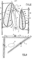
- Figure 12 shows a leg 10 in which an anomaly has to be investigated in the joint 12 of the femur 11 in the pelvis 13.
- two water cushions 14 and 15 filled with liquid 16 are placed on each side of leg 10 so that the shape of the cushions 14 and 15 conform to the profile of the leg 10.
- Within these cushions 14 and 15 are the base lines 17 and 18 that do not intersect and that carry either ultrasonic or other transmitters 19 and corresponding receivers 20 evenly spaced apart.
- the transmitters 19 are triggered in sequence so as to obtain all. the signal paths joining the transmitters 19 to the receivers 20. The shape and dimensions of the anomaly are then determined as shown previously.
- the distance through the discontinuity is first calculated on each line for all the signal lines.
- the computer stores in memory this distance for each line. All the lines of the same plane are selected together and, if necessary, these distances can be mathematically smoothed for reasons of continuity.
- the computer determines the points of tangency and the coordinates of such points (normally six for three boreholes) and indicates that these lines of tangency have been used. At this stage, the surface of the discontinuity is only known by these points of tangency and by the corresponding tangent lines. These points and the tangent lines are then stored, i.e. in rectangular coordinates.
- the distance through the discontinuity from the given point is used. If no analyzed signal line passed exactly through the point, then the distance is obtained from two adjacent signal lines in the same plane. The computer then stores this line in memory.
- a new point on the surface of the discontinuity is obtained and stored in the computer memory. If there is any doubt as to the position of this new point or if the corresponding tangent is not known, continuity is used to obtain a good estimated location.
- the tangent in the starting point is used to determine, in the planar section, the tangent in the final point (coordinating the result with those of the adjacent lines).
- the new point is close to an already determined point, it has to be coherent with the tangents; if this is not the case, the extreme points will be ignored.
- the procedure is then carried on so as to find other points of the discontinuity corresponding to known signal lines, and this is continued until a sufficient number a valid points to fully characterize the discontinuity are obtained. If there are not enough points, a criterion of continuity will be employed for intermediate points.
- the discontinuity in any form required, using available video display systems. It is, for example, practical to image the discontinuity through a number of planar sections through selected planes. It is also practical to display an isometric or perspective view of the discontinuity. In the same manner, the discontinuity can be shown in shadows more or less deep, corresponding to the depth or thickness of the discontinuity.
- the discontinuity to be analyzed may involve objects immersed in a liquid, or temperature discontinuities either underground or inside the human body.
- one of the boreholes can be perpendicular to the surface of the ground, but it is desirable that at least two boreholes or transducer lines do not intersect and that the lines joining those two boreholes or base lines intercept the whole of the volume to be analysed.
- the transducer lines need not be straight and can be replaced by either parts of a circle or by other curves, preferably curves which are readily susceptible of mathematical analysis as to location of the system components and the like.
- the whole of the measurement and analysis can be done automatically by using a predetermined steps and the computed results can either be printed or displayed on a screen or presented in any desired manner.
- Alternatives involve the use of collimated signals, or signals modulated in frequency or in phase, or a series of pulses in order to get a better identification.
- echos and diffracted signals may also be detected.
- additional boreholes either intersecting one of the boreholes, or non-intersecting, may be employed, to provide redundancy or further date for averaging to improve the resolution of the image or configuration data. Accordingly, the present invention is not limited to the system and method as shown in the drawings and described in detail hereinabove.
Landscapes
- Life Sciences & Earth Sciences (AREA)
- Physics & Mathematics (AREA)
- Health & Medical Sciences (AREA)
- Engineering & Computer Science (AREA)
- Acoustics & Sound (AREA)
- Environmental & Geological Engineering (AREA)
- Geology (AREA)
- Remote Sensing (AREA)
- General Life Sciences & Earth Sciences (AREA)
- General Physics & Mathematics (AREA)
- Geophysics (AREA)
- Rheumatology (AREA)
- Heart & Thoracic Surgery (AREA)
- Biophysics (AREA)
- Nuclear Medicine, Radiotherapy & Molecular Imaging (AREA)
- Pathology (AREA)
- Radiology & Medical Imaging (AREA)
- Biomedical Technology (AREA)
- Orthopedic Medicine & Surgery (AREA)
- Medical Informatics (AREA)
- Molecular Biology (AREA)
- Surgery (AREA)
- Animal Behavior & Ethology (AREA)
- General Health & Medical Sciences (AREA)
- Public Health (AREA)
- Veterinary Medicine (AREA)
- Geophysics And Detection Of Objects (AREA)
Applications Claiming Priority (2)
| Application Number | Priority Date | Filing Date | Title |
|---|---|---|---|
| FR8208883A FR2527339A1 (fr) | 1982-05-21 | 1982-05-21 | Procede et installation pour analyser des discontinuites situees dans un milieu sensiblement homogene |
| FR8208883 | 1982-05-21 |
Publications (2)
| Publication Number | Publication Date |
|---|---|
| EP0099764A1 true EP0099764A1 (fr) | 1984-02-01 |
| EP0099764B1 EP0099764B1 (fr) | 1987-10-28 |
Family
ID=9274234
Family Applications (1)
| Application Number | Title | Priority Date | Filing Date |
|---|---|---|---|
| EP83401012A Expired EP0099764B1 (fr) | 1982-05-21 | 1983-05-20 | Procédé et disposition pour analyser des discontinuités dans un milieu assez homogène |
Country Status (5)
| Country | Link |
|---|---|
| US (1) | US4495816A (fr) |
| EP (1) | EP0099764B1 (fr) |
| CA (1) | CA1199111A (fr) |
| DE (1) | DE3374224D1 (fr) |
| FR (1) | FR2527339A1 (fr) |
Cited By (5)
| Publication number | Priority date | Publication date | Assignee | Title |
|---|---|---|---|---|
| WO1990001296A1 (fr) * | 1988-08-10 | 1990-02-22 | Board Of Regents, The University Of Texas System | Procede et appareil pour l'analyse des proprietes d'un materiau par reflexion d'ultrasons |
| EP0383288A1 (fr) * | 1989-02-16 | 1990-08-22 | Fujitsu Limited | Appareil diagnostique à ultrasons pour caractériser un tissu par analyse de rayonnement rétrodiffusé |
| US5143070A (en) * | 1989-11-17 | 1992-09-01 | The University Of Texas Systems Board Of Regents | Transaxial compression technique for sound velocity estimation |
| US5247937A (en) * | 1989-11-17 | 1993-09-28 | Board Of Regents, The University Of Texas System | Transaxial compression technique for sound velocity estimation |
| US5293870A (en) * | 1989-11-17 | 1994-03-15 | Board Of Regents The University Of Texas System | Method and apparatus for elastographic measurement and imaging |
Families Citing this family (14)
| Publication number | Priority date | Publication date | Assignee | Title |
|---|---|---|---|---|
| JPS6060838A (ja) * | 1983-09-13 | 1985-04-08 | 富士通株式会社 | 超音波音場観測装置 |
| US4543648A (en) * | 1983-12-29 | 1985-09-24 | Schlumberger Technology Corporation | Shot to shot processing for measuring a characteristic of earth formations from inside a borehole |
| EP0276205B1 (fr) * | 1986-05-05 | 1990-09-12 | Akademiet For De Tekniske Videnskaber, Svejsecentralen | Systeme d'examen ultrasonore |
| DE3704339A1 (de) * | 1987-02-12 | 1988-08-25 | Eden Medizinische Elektronik G | Vorrichtung zur bestimmung der lage eines objektes |
| US4888720A (en) * | 1987-12-07 | 1989-12-19 | Fryer Glenn E | Tunnel measuring apparatus and method |
| FR2624634B1 (fr) * | 1987-12-09 | 1994-04-29 | Schlumberger Etienne | Procede et dispositif permettant de reconstituer la forme et la position d'objets dans l'espace |
| US4911014A (en) * | 1988-07-22 | 1990-03-27 | Akademiet For De Tekniske Videnskaber, Svejsecentralen | Method of analyzing and evaluating the results of an ultrasonic examination |
| US5111696A (en) * | 1989-01-24 | 1992-05-12 | Akademiet For De Tekniske Videnskaber, Svejsecentralen | Method of visualizing reflection characteristic in ultrasonic examination |
| ES2080378T5 (es) * | 1991-06-27 | 2004-01-16 | Ccs Technology, Inc. | Manguito de cable. |
| US5987346A (en) | 1993-02-26 | 1999-11-16 | Benaron; David A. | Device and method for classification of tissue |
| US5673697A (en) * | 1996-04-24 | 1997-10-07 | Raytheon Company | High-resolution three, dimensional ultrasound imaging device |
| EP1465530B1 (fr) * | 2002-01-07 | 2007-05-23 | GE Medical Systems Israel Ltd. | Systeme et procede de cartographie d'irregularites de tissu dur |
| US20070043290A1 (en) * | 2005-08-03 | 2007-02-22 | Goepp Julius G | Method and apparatus for the detection of a bone fracture |
| US8259997B2 (en) * | 2009-07-13 | 2012-09-04 | Moment Factory | Real-time tracking system |
Citations (7)
| Publication number | Priority date | Publication date | Assignee | Title |
|---|---|---|---|---|
| US2388703A (en) * | 1941-09-20 | 1945-11-13 | United Geophysical Company Inc | Geological prospecting system |
| FR1497496A (fr) * | 1966-05-06 | 1967-10-13 | Massiot Philips Sa | Procédé et appareil d'analyse par ultrasons |
| GB1161080A (en) * | 1966-02-03 | 1969-08-13 | Eberhard Borges | A Process and Equipment for Detecting Dislocations in Rock Strata. |
| US3685051A (en) * | 1969-03-06 | 1972-08-15 | Tetra Tech | Holographic imaging system using crossed linear arrays of energy sources and sensors |
| US4083232A (en) * | 1976-04-23 | 1978-04-11 | California Institute Of Technology | Medical tomograph system using ultrasonic transmission |
| US4130112A (en) * | 1976-11-15 | 1978-12-19 | The United States Of America As Represented By The Administrator Of The National Aeronautics And Space Administration | Coupling apparatus for ultrasonic medical diagnostic system |
| GB2023830A (en) * | 1978-06-22 | 1980-01-03 | Philips Nv | Determining the internal structure of a body by means of acoustic beams |
Family Cites Families (5)
| Publication number | Priority date | Publication date | Assignee | Title |
|---|---|---|---|---|
| US2599688A (en) * | 1951-01-17 | 1952-06-10 | Newmont Mining Corp | Resistivity method for determining ore continuity |
| US4340934A (en) * | 1971-09-07 | 1982-07-20 | Schlumberger Technology Corporation | Method of generating subsurface characteristic models |
| US4172250A (en) * | 1973-01-19 | 1979-10-23 | Schlumberger Technology Corporation | Acoustic well logging with threshold adjustment |
| JPS5599240A (en) * | 1979-01-22 | 1980-07-29 | Tokyo Shibaura Electric Co | Ct scanner |
| US4322974A (en) * | 1980-02-05 | 1982-04-06 | New York University | Ultrasound scanner |
-
1982
- 1982-05-21 FR FR8208883A patent/FR2527339A1/fr active Granted
-
1983
- 1983-05-17 US US06/495,265 patent/US4495816A/en not_active Expired - Fee Related
- 1983-05-20 DE DE8383401012T patent/DE3374224D1/de not_active Expired
- 1983-05-20 CA CA000428597A patent/CA1199111A/fr not_active Expired
- 1983-05-20 EP EP83401012A patent/EP0099764B1/fr not_active Expired
Patent Citations (7)
| Publication number | Priority date | Publication date | Assignee | Title |
|---|---|---|---|---|
| US2388703A (en) * | 1941-09-20 | 1945-11-13 | United Geophysical Company Inc | Geological prospecting system |
| GB1161080A (en) * | 1966-02-03 | 1969-08-13 | Eberhard Borges | A Process and Equipment for Detecting Dislocations in Rock Strata. |
| FR1497496A (fr) * | 1966-05-06 | 1967-10-13 | Massiot Philips Sa | Procédé et appareil d'analyse par ultrasons |
| US3685051A (en) * | 1969-03-06 | 1972-08-15 | Tetra Tech | Holographic imaging system using crossed linear arrays of energy sources and sensors |
| US4083232A (en) * | 1976-04-23 | 1978-04-11 | California Institute Of Technology | Medical tomograph system using ultrasonic transmission |
| US4130112A (en) * | 1976-11-15 | 1978-12-19 | The United States Of America As Represented By The Administrator Of The National Aeronautics And Space Administration | Coupling apparatus for ultrasonic medical diagnostic system |
| GB2023830A (en) * | 1978-06-22 | 1980-01-03 | Philips Nv | Determining the internal structure of a body by means of acoustic beams |
Cited By (6)
| Publication number | Priority date | Publication date | Assignee | Title |
|---|---|---|---|---|
| WO1990001296A1 (fr) * | 1988-08-10 | 1990-02-22 | Board Of Regents, The University Of Texas System | Procede et appareil pour l'analyse des proprietes d'un materiau par reflexion d'ultrasons |
| EP0383288A1 (fr) * | 1989-02-16 | 1990-08-22 | Fujitsu Limited | Appareil diagnostique à ultrasons pour caractériser un tissu par analyse de rayonnement rétrodiffusé |
| US5097836A (en) * | 1989-02-16 | 1992-03-24 | Fujitsu Limited | Untrasound diagnostic equipment for calculating and displaying integrated backscatter or scattering coefficients by using scattering power or scattering power spectrum of blood |
| US5143070A (en) * | 1989-11-17 | 1992-09-01 | The University Of Texas Systems Board Of Regents | Transaxial compression technique for sound velocity estimation |
| US5247937A (en) * | 1989-11-17 | 1993-09-28 | Board Of Regents, The University Of Texas System | Transaxial compression technique for sound velocity estimation |
| US5293870A (en) * | 1989-11-17 | 1994-03-15 | Board Of Regents The University Of Texas System | Method and apparatus for elastographic measurement and imaging |
Also Published As
| Publication number | Publication date |
|---|---|
| FR2527339B1 (fr) | 1985-03-01 |
| EP0099764B1 (fr) | 1987-10-28 |
| CA1199111A (fr) | 1986-01-07 |
| US4495816A (en) | 1985-01-29 |
| DE3374224D1 (en) | 1987-12-03 |
| FR2527339A1 (fr) | 1983-11-25 |
Similar Documents
| Publication | Publication Date | Title |
|---|---|---|
| US4495816A (en) | Process and system for analyzing discontinuities in reasonably homogeneous medium | |
| US6374201B1 (en) | Method for 3D modelling of the impedance of a heterogeneous medium | |
| US6135960A (en) | High-resolution, three-dimensional whole body ultrasound imaging system | |
| US4322974A (en) | Ultrasound scanner | |
| US20130190626A1 (en) | Determining location of, and imaging, a subsurface boundary | |
| JP2005503539A (ja) | 地中探索レーダを用いて埋められている物体を識別するための方法および装置 | |
| AU7169387A (en) | Method for selection of mining and drilling sites using synthesized three dimensional seismic data | |
| CN101803933A (zh) | 肝脏纤维化检测装置 | |
| JP2000512385A (ja) | 伝搬する波動場のサンプリング及び復元 | |
| EP4558313B1 (fr) | Tête de capteur hybride pour inspection de surface | |
| US6700833B2 (en) | Acoustical imaging interferometer for detection of buried underwater objects | |
| US7330792B2 (en) | Method for reconstructing complex wave attributes from limited view measurements | |
| CN112904348B (zh) | 一种三维探测方法、装置、设备和存储介质 | |
| JPH0361915B2 (fr) | ||
| US20070215823A1 (en) | Imaging method based on calculation of topological energy | |
| Sambuelli et al. | Photogrammetry and 3-D ultrasonic tomography to estimate the integrity of two sculptures of the Egyptian Museum of Turin | |
| Delprat‐Jannaud et al. | Reflection tomography: How to handle multiple arrivals? | |
| Boyd | Limited-angle computed tomography for sandwich structures using data fusion | |
| JP2003107164A (ja) | 開口合成探査装置 | |
| Schuster | A fast exact numerical solution for the acoustic response of concentric cylinders with penetrable interfaces | |
| Wang et al. | Ray tracing in isotropic and anisotropic materials: Application to tomographic image reconstruction | |
| JPH0363587A (ja) | 地中埋設物探査装置 | |
| Veiste | Image Reconstruction in Ultrasound Tomography | |
| Sambuelli et al. | Photogrammetry joins Ultrasonic Tests in the 3D modeling of fractures: an application to the preservation of two Egyptian Sculptures. | |
| Send et al. | Aspects of acoustic transponder surveys and acoustic navigation |
Legal Events
| Date | Code | Title | Description |
|---|---|---|---|
| PUAI | Public reference made under article 153(3) epc to a published international application that has entered the european phase |
Free format text: ORIGINAL CODE: 0009012 |
|
| 17P | Request for examination filed |
Effective date: 19830526 |
|
| AK | Designated contracting states |
Designated state(s): CH DE GB LI NL SE |
|
| GRAA | (expected) grant |
Free format text: ORIGINAL CODE: 0009210 |
|
| AK | Designated contracting states |
Kind code of ref document: B1 Designated state(s): CH DE GB LI NL SE |
|
| REF | Corresponds to: |
Ref document number: 3374224 Country of ref document: DE Date of ref document: 19871203 |
|
| PLBE | No opposition filed within time limit |
Free format text: ORIGINAL CODE: 0009261 |
|
| STAA | Information on the status of an ep patent application or granted ep patent |
Free format text: STATUS: NO OPPOSITION FILED WITHIN TIME LIMIT |
|
| 26N | No opposition filed | ||
| PGFP | Annual fee paid to national office [announced via postgrant information from national office to epo] |
Ref country code: SE Payment date: 19920513 Year of fee payment: 10 |
|
| PGFP | Annual fee paid to national office [announced via postgrant information from national office to epo] |
Ref country code: GB Payment date: 19920514 Year of fee payment: 10 |
|
| PGFP | Annual fee paid to national office [announced via postgrant information from national office to epo] |
Ref country code: CH Payment date: 19920518 Year of fee payment: 10 |
|
| PGFP | Annual fee paid to national office [announced via postgrant information from national office to epo] |
Ref country code: NL Payment date: 19920531 Year of fee payment: 10 |
|
| PGFP | Annual fee paid to national office [announced via postgrant information from national office to epo] |
Ref country code: DE Payment date: 19920721 Year of fee payment: 10 |
|
| PG25 | Lapsed in a contracting state [announced via postgrant information from national office to epo] |
Ref country code: GB Effective date: 19930520 |
|
| PG25 | Lapsed in a contracting state [announced via postgrant information from national office to epo] |
Ref country code: SE Effective date: 19930521 |
|
| PG25 | Lapsed in a contracting state [announced via postgrant information from national office to epo] |
Ref country code: LI Effective date: 19930531 Ref country code: CH Effective date: 19930531 |
|
| PG25 | Lapsed in a contracting state [announced via postgrant information from national office to epo] |
Ref country code: NL Effective date: 19931201 |
|
| NLV4 | Nl: lapsed or anulled due to non-payment of the annual fee | ||
| GBPC | Gb: european patent ceased through non-payment of renewal fee |
Effective date: 19930520 |
|
| REG | Reference to a national code |
Ref country code: CH Ref legal event code: PL |
|
| PG25 | Lapsed in a contracting state [announced via postgrant information from national office to epo] |
Ref country code: DE Effective date: 19940201 |
|
| EUG | Se: european patent has lapsed |
Ref document number: 83401012.6 Effective date: 19931210 |