EP0099996A2 - Appareil pour chauffer des assiettes empilées - Google Patents
Appareil pour chauffer des assiettes empilées Download PDFInfo
- Publication number
- EP0099996A2 EP0099996A2 EP83106376A EP83106376A EP0099996A2 EP 0099996 A2 EP0099996 A2 EP 0099996A2 EP 83106376 A EP83106376 A EP 83106376A EP 83106376 A EP83106376 A EP 83106376A EP 0099996 A2 EP0099996 A2 EP 0099996A2
- Authority
- EP
- European Patent Office
- Prior art keywords
- carrier
- switch
- housing
- cover
- lowering
- Prior art date
- Legal status (The legal status is an assumption and is not a legal conclusion. Google has not performed a legal analysis and makes no representation as to the accuracy of the status listed.)
- Granted
Links
- 238000010438 heat treatment Methods 0.000 title claims description 6
- 230000004888 barrier function Effects 0.000 claims description 3
- 230000008878 coupling Effects 0.000 claims description 2
- 238000010168 coupling process Methods 0.000 claims description 2
- 238000005859 coupling reaction Methods 0.000 claims description 2
- 230000001960 triggered effect Effects 0.000 claims 1
- 230000006835 compression Effects 0.000 description 2
- 238000007906 compression Methods 0.000 description 2
- 238000010586 diagram Methods 0.000 description 2
- 230000002093 peripheral effect Effects 0.000 description 2
- 241001464057 Electroma Species 0.000 description 1
- 230000005540 biological transmission Effects 0.000 description 1
- 238000010276 construction Methods 0.000 description 1
- 238000000034 method Methods 0.000 description 1
- 230000001105 regulatory effect Effects 0.000 description 1
Images


Classifications
-
- A—HUMAN NECESSITIES
- A47—FURNITURE; DOMESTIC ARTICLES OR APPLIANCES; COFFEE MILLS; SPICE MILLS; SUCTION CLEANERS IN GENERAL
- A47J—KITCHEN EQUIPMENT; COFFEE MILLS; SPICE MILLS; APPARATUS FOR MAKING BEVERAGES
- A47J39/00—Heat-insulated warming chambers; Cupboards with heating arrangements for warming kitchen utensils
- A47J39/02—Dish-warmers; Devices to keep food hot
- A47J39/025—Dish-warmers; Devices to keep food hot for warming dishes without food before use
-
- B—PERFORMING OPERATIONS; TRANSPORTING
- B65—CONVEYING; PACKING; STORING; HANDLING THIN OR FILAMENTARY MATERIAL
- B65G—TRANSPORT OR STORAGE DEVICES, e.g. CONVEYORS FOR LOADING OR TIPPING, SHOP CONVEYOR SYSTEMS OR PNEUMATIC TUBE CONVEYORS
- B65G1/00—Storing articles, individually or in orderly arrangement, in warehouses or magazines
- B65G1/02—Storage devices
- B65G1/04—Storage devices mechanical
- B65G1/06—Storage devices mechanical with means for presenting articles for removal at predetermined position or level
- B65G1/07—Storage devices mechanical with means for presenting articles for removal at predetermined position or level the upper article of a pile being always presented at the same predetermined level
Definitions
- Plate warmers are known in different versions. Some of them have cabinet-shaped housings with doors on one or two sides. Plate and cup warmers are also known, the housings of which have two side opening openings that can be closed by flaps over the entire height; through these control openings, e.g. with both hands a stack of plates for loading and unloading can be recorded. Plate warmers with round or polygonal, shaft-like housings with round doors in the center are also on the market.
- the object of the invention is to provide an apparatus for heating stackable tableware, in which these disadvantages are avoided and which is easy to use.
- Plate stackers with springs are known, which are pressed together by a plate stack. When plates are removed, the springs are relieved and push the remaining plates upwards until the weight is balanced. As a result, the upper end of the stack of plates should always be approximately at the same height. With this device, however, it is not possible to fully achieve the compensation. Even plates of the same type have different weights. Therefore If you arrange the device in a shaft-like housing with an open top, some plates will always protrude beyond the opening edge. Closing with a lid is therefore not possible. The plate stacker could not be designed as a plate warmer because the heat losses would be far too high.
- the stated object of the invention is achieved with an apparatus which is characterized by a shaft-like heatable housing with an open top which can be closed with a lid, a support for a stack of dishes arranged in the housing, which can be raised and lowered, and a motor-driven device for lifting and lowering the carrier.
- a motor-driven device can also be provided for opening and closing the cover, and the arrangement can be such that the cover can be opened by actuating a push-button switch and then the carrier can be raised or lowered to a desired height.
- a time delay means can be started which, after a predetermined period of time, switches on a drive means for lowering the carrier.
- This drive means can be switched off by means of a sensor device which detects the passage of the upper end of a stack of dishes standing on the carrier through the upper housing opening. The lid can then also be closed automatically.
- the plate warmer shown has a frame with a square lower horizontal frame 1 and an upper horizontal frame plate 2, the outline of which is also square.
- the frame 1 is connected to the plate 2 on both sides via two vertical guide rails 3, 4 and 5, 6, respectively.
- the lower frame 1 stands on supports 7 which can expediently carry rollers (not shown).
- the outer casing of the plate warmer, with four vertical walls, has been omitted from the drawing.
- a circular cylindrical, shaft-like heat-insulated inner housing 8 is arranged, the top of which is open, so that the interior of the housing 8 is accessible through a circular opening 9 in the frame plate 2.
- two opposite electrical heating rods 10 are arranged in the same, vertically mounted on the housing wall in bulges.
- a horizontal support plate 11 which carries a stack of plates (not shown) to be heated.
- the carrier plate 11 is attached to a carriage or carriage 12; it can be removed to clean the inside of the housing, for example with a vacuum hose.
- Lateral arms of the carriage or carriage 12 extend through two narrow slot openings 13 which are formed opposite one another in the peripheral wall of the housing 8 and extend vertically over its entire useful height. The ends of these arms are vertically displaceably guided in the guide rails 3, 4 and 5, 6, for example by means of plastic sliding shoes 14. Furthermore, the ends of the arms are each screwed to one of two endless link chains 15, which outside the housing 8 in circumscribe vertical levels.
- the chains 15 run above freely rotatable ket tenheels 16 and below via drive sprockets 17 which sit on drive shafts 18 (Fig. 1) which can be rotated by a drive electric motor 19 via a gear 20.
- the drive unit with the chain wheels 17, the shafts 18, the motor 19 and the transmission 20 is mounted on a base plate 21.
- This base plate 21 is pressed down by adjustable compression springs 22, whereby the chains 15 are tensioned.
- the clamping screws 23 of the compression springs 22 run in threaded bushes 24 which are welded to the lower frame 1.
- the upper access opening 9 to the housing 8 formed in the upper frame plate 2 and sloping upwards can be closed by an automatically closing and opening, heat-insulated cover 26.
- the cover 26 is pivotable about an axis 27, on which a prestressed torsion spring 28 is arranged, which presses the cover into its open position.
- a tube 29 is articulated on the cover 26 on one side, which extends downward through a slot-shaped recess in the upper frame plate 2 and is guided there telescopically on a pull rod 30 which is articulated on a crank 31 of a geared motor 32.
- a ratchet saddle 33 is attached to the lower end of the tube 29.
- retractable pawl 35 is fastened together with the electromagnet on the pull rod 30 so that when the cover 26 is closed, the pawl 35 engages over the pawl saddle 33 and holds the cover 26 closed when the crank arm 31 is directed downward.
- the pawl 35 can then be withdrawn by energizing the electromagnet 34, so that the cover 26 springs open due to the force of the spring 28.
- a resilient stop 36 is attached to the tube 29, which resiliently intercepts the upward swing of the cover 26 on the underside of the frame plate 2.
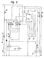
- FIG. 3 shows an electrical circuit diagram of the plate heater.
- the heating rods 10 are switched on by a main switch 40, the temperature in the housing 8 being regulated by a thermostat switch 41 with an associated temperature sensor 42.
- two push button switches 43 and 44 (not shown in FIGS. 1 and 2) are arranged, which serve to raise or lower the carrier plate 11 in the housing 8.
- the push-button switches 43 and 44 are each equipped with two closing contacts a and b and an opening contact c.
- the opening contact c of the switch 43 interrupts a time relay in an electronic circuit 47 and thereby pulls it open. After the switch 43 is released, the time relay expires and closes a contact 47a in the electronic circuit after a predetermined period of time.
- a switch 47b is switched from the position shown and, starting from the timing relay contact 47a, closes a circuit via a lower stroke limit switch 50 to the drive motor 19. This moves the carrier plate 11 with the stack of plates downwards until the infrared barrier 48, 49 is free.
- the changeover switch 47b in the electronic circuit 47 switches to the position shown and closes via a limit switch 51 actuated by the cover 26, which is in the position shown as long as the cover 26 is not closed Circuit to the geared motor 32.
- the geared motor 32 begins to rotate and the crank 31 closes the cover 26 in the manner already described. As soon as the cover 26 is closed, it switches the limit switch 51 from the position shown, whereby the motor 32 is switched off .
- the geared motor 32 is now connected in parallel to the rectifier of the electromagnet 34. The next time the pushbutton switch 43 is actuated, it therefore begins to run briefly until the cover 26 has left its closed position and the limit switch 51 switches back to the position shown. The motor 32 thus acts as a release aid for the magnet 34.
- the push button switch 43 is of course actuated to trigger the processes described when plates are to be removed from the plate warmer.
- the push-button switch 44 is actuated. This has the same function as the switch 43 with the exception that after opening the cover 26 a circuit via the limit switch 45, the contact a of the switch 44 and the lower stroke limit switch 50 to the motor 19 is closed in such a way that it lowers the carrier plate 11 in the housing 8.
- the means for guiding and driving the support plate 11 which can be raised and lowered in the housing 8 can be designed in any suitable manner.
- the device for lifting and lowering the support plate 11 and the device for opening and Closing the cover 26 could be driven by a common drive motor via switchable couplings as the drive means.
Landscapes
- Engineering & Computer Science (AREA)
- Food Science & Technology (AREA)
- Mechanical Engineering (AREA)
- Baking, Grill, Roasting (AREA)
- Cookers (AREA)
- General Preparation And Processing Of Foods (AREA)
- Devices For Warming Or Keeping Food Or Tableware Hot (AREA)
- Washing And Drying Of Tableware (AREA)
Priority Applications (1)
| Application Number | Priority Date | Filing Date | Title |
|---|---|---|---|
| AT83106376T ATE29832T1 (de) | 1982-07-21 | 1983-06-30 | Apparat zum erwaermen von stapelbarem essgeschirr. |
Applications Claiming Priority (2)
| Application Number | Priority Date | Filing Date | Title |
|---|---|---|---|
| CH4439/82A CH657513A5 (de) | 1982-07-21 | 1982-07-21 | Apparat zum erwaermen von stapelbarem essgeschirr. |
| CH4439/82 | 1982-07-21 |
Publications (3)
| Publication Number | Publication Date |
|---|---|
| EP0099996A2 true EP0099996A2 (fr) | 1984-02-08 |
| EP0099996A3 EP0099996A3 (en) | 1984-06-06 |
| EP0099996B1 EP0099996B1 (fr) | 1987-09-23 |
Family
ID=4276147
Family Applications (1)
| Application Number | Title | Priority Date | Filing Date |
|---|---|---|---|
| EP83106376A Expired EP0099996B1 (fr) | 1982-07-21 | 1983-06-30 | Appareil pour chauffer des assiettes empilées |
Country Status (5)
| Country | Link |
|---|---|
| US (1) | US4508959A (fr) |
| EP (1) | EP0099996B1 (fr) |
| AT (1) | ATE29832T1 (fr) |
| CH (1) | CH657513A5 (fr) |
| DE (1) | DE3373779D1 (fr) |
Cited By (2)
| Publication number | Priority date | Publication date | Assignee | Title |
|---|---|---|---|---|
| FR2562780A1 (fr) * | 1984-04-13 | 1985-10-18 | Lebon Daniel | Dispositif support mobile avec combines pour la preparation et la distribution d'aliments |
| FR2615089A1 (fr) * | 1987-05-11 | 1988-11-18 | Proust Robert | Foyer a hauteur modulable pour grilloir |
Families Citing this family (8)
| Publication number | Priority date | Publication date | Assignee | Title |
|---|---|---|---|---|
| ES2054588B1 (es) * | 1993-01-27 | 1995-02-16 | Navarro Eduardo Tarrats | Aparato para el calentamiento de platos para coccion. |
| US5697577A (en) * | 1996-02-27 | 1997-12-16 | Ogden; Terry P. | Premoistened toilet paper dispenser |
| US6305500B1 (en) | 1999-08-25 | 2001-10-23 | Maxtor Corporation | Material delivery system for clean room-like environments |
| WO2011141857A2 (fr) * | 2010-05-10 | 2011-11-17 | Mansonia Joinery (Pty) Ltd | Chariot de service |
| US11390308B2 (en) | 2019-03-07 | 2022-07-19 | Dishcraft Robotics, Inc. | Automated dish drop |
| US10654504B1 (en) | 2019-03-07 | 2020-05-19 | Dishcraft Robotics, Inc. | Dish stacking cart |
| US10974750B2 (en) | 2019-03-07 | 2021-04-13 | Dishcraft Robotics, Inc. | Adjustable dish stacking cart |
| US11198461B2 (en) * | 2019-03-07 | 2021-12-14 | Dishcraft Robotics, Inc. | Dish collection and dispensing system |
Family Cites Families (19)
| Publication number | Priority date | Publication date | Assignee | Title |
|---|---|---|---|---|
| CA626277A (en) * | 1961-08-29 | Luscher Paul | Container for the warming-up of piled objects, in particular dishes and plates | |
| NL76451C (fr) * | ||||
| US2279936A (en) * | 1939-12-28 | 1942-04-14 | Damon D Brodie | Vending machine |
| US2433560A (en) * | 1944-10-30 | 1947-12-30 | Jr Samuel C Hurley | Hopper controller for uniformly feeding unit articles |
| US2477239A (en) * | 1945-09-17 | 1949-07-26 | William W Cease | Dispensing apparatus |
| US2707142A (en) * | 1949-06-01 | 1955-04-26 | American Mach & Foundry | Material receiving, storing, and dispensing apparatus |
| DE1188254B (de) * | 1957-05-14 | 1965-03-04 | Paul Luescher | Behaelter zum Aufwaermen von Essgeschirr |
| US3033633A (en) * | 1960-01-28 | 1962-05-08 | American Mach & Foundry | Self-leveling dispenser |
| US3167369A (en) * | 1963-10-21 | 1965-01-26 | William T Haag | Automatic article dispenser |
| US3315840A (en) * | 1963-12-23 | 1967-04-25 | Ibm | Automatic disk stacking device |
| US3351741A (en) * | 1964-07-08 | 1967-11-07 | Shelley Mfg Company | Dish-dispensing apparatus |
| CH430087A (de) * | 1965-06-08 | 1967-02-15 | Kreis Hepp Ag | Vorrichtung zur Abgabe und Verteilung von Scheiben zum Warmhalten von Speisen |
| GB1088683A (en) * | 1965-06-09 | 1967-10-25 | American Mach & Foundry | Temperature control of a housing containing a dispensing mechanism for stacked articles |
| US3493725A (en) * | 1967-03-15 | 1970-02-03 | Lincoln Mfg Co | Transportable and heated container for dish elevator |
| US3536891A (en) * | 1967-08-21 | 1970-10-27 | Veloise W Lee | Infrared heated dish storage apparatus |
| CH473572A (de) * | 1968-05-06 | 1969-06-15 | Kochanlagenbau Stolpen Veb | Geschirrspender |
| US3752549A (en) * | 1971-11-15 | 1973-08-14 | Restaurant Technology | Food holding cabinet |
| US4108518A (en) * | 1977-03-31 | 1978-08-22 | Angst Edy P | Banquet food serving apparatus |
| US4391387A (en) * | 1979-09-04 | 1983-07-05 | Standard Change-Makers, Inc. | Magnetic ticket dispenser |
-
1982
- 1982-07-21 CH CH4439/82A patent/CH657513A5/de not_active IP Right Cessation
-
1983
- 1983-06-30 DE DE8383106376T patent/DE3373779D1/de not_active Expired
- 1983-06-30 EP EP83106376A patent/EP0099996B1/fr not_active Expired
- 1983-06-30 AT AT83106376T patent/ATE29832T1/de not_active IP Right Cessation
- 1983-07-12 US US06/513,096 patent/US4508959A/en not_active Expired - Fee Related
Cited By (3)
| Publication number | Priority date | Publication date | Assignee | Title |
|---|---|---|---|---|
| FR2562780A1 (fr) * | 1984-04-13 | 1985-10-18 | Lebon Daniel | Dispositif support mobile avec combines pour la preparation et la distribution d'aliments |
| EP0165891A1 (fr) * | 1984-04-13 | 1985-12-27 | Daniel Le Bon | Dispositif support mobile avec différents combinés pour la préparation, le conditionnement, le stockage et la distribution d'aliments |
| FR2615089A1 (fr) * | 1987-05-11 | 1988-11-18 | Proust Robert | Foyer a hauteur modulable pour grilloir |
Also Published As
| Publication number | Publication date |
|---|---|
| ATE29832T1 (de) | 1987-10-15 |
| EP0099996B1 (fr) | 1987-09-23 |
| DE3373779D1 (en) | 1987-10-29 |
| EP0099996A3 (en) | 1984-06-06 |
| CH657513A5 (de) | 1986-09-15 |
| US4508959A (en) | 1985-04-02 |
Similar Documents
| Publication | Publication Date | Title |
|---|---|---|
| EP0099996B1 (fr) | Appareil pour chauffer des assiettes empilées | |
| US4099712A (en) | Automatic sheet handling apparatus | |
| DE2916730C2 (fr) | ||
| DE4236740A1 (de) | Herd mit mindestens einem ausschwenkbaren Gargutträger | |
| EP0128373B1 (fr) | Dispositif pour recevoir et déconsigner des bouteilles vides | |
| EP0541981A1 (fr) | Lit | |
| WO2008067968A1 (fr) | Appareil de vente pour plats préparés | |
| DE3114024A1 (de) | Materialausgabegeraet | |
| EP0087111B1 (fr) | Four de cuisson, en particulier four à vide pour travaux de céramique dentaire | |
| DE19620973A1 (de) | Aufnahmebox für den Unterflureinbau | |
| DE29617960U1 (de) | Aufnahmebox für den Unterflureinbau | |
| DE2257349A1 (de) | Vorrichtung zum herstellen von deckeln | |
| DE1108145B (de) | Vorrichtung zum selbsttaetigen Beladen von Stapelplatten mit schichtweise gestapelten Lagen von Stueckgut | |
| DE2354284B2 (de) | Brotröster | |
| DE69004371T2 (de) | Müllpresse, insbesondere für Hausmüll. | |
| DE1116599B (de) | Vorrichtung zum Abbauen eines Stueckgutstapels | |
| EP0769577A2 (fr) | Procédé et appareillage pour le tirage des monocristaux d'un bain fondu dans un creuset | |
| DE2218225C3 (de) | Mikrowellenherd | |
| DE3875969T2 (de) | Vorrichtung zum oeffnen und schliessen einer filmkassette. | |
| DE2332808A1 (de) | Vorrichtung zum umsetzen von stueckgut aus einer rollenbahn | |
| DE10120863C2 (de) | Filterpresse mit Filterplatten | |
| DE1584244B1 (de) | Antriebsvorrichtung fuer ein in eine deckennahe Offenstellung hochschiebbares Tor | |
| DE2942890A1 (de) | Elektrischer brotroester mit automatischer ausloesung | |
| CA1109088A (fr) | Butee d'extremite et poussoirs lateraux reglables pour systeme d'empilage de feuilles | |
| DE1584244C (de) | Antriebsvorrichtung fur ein in eine deckennahe Offenstellung hochschiebbares Tor |
Legal Events
| Date | Code | Title | Description |
|---|---|---|---|
| PUAI | Public reference made under article 153(3) epc to a published international application that has entered the european phase |
Free format text: ORIGINAL CODE: 0009012 |
|
| AK | Designated contracting states |
Designated state(s): AT BE DE FR GB IT LU NL |
|
| PUAL | Search report despatched |
Free format text: ORIGINAL CODE: 0009013 |
|
| AK | Designated contracting states |
Designated state(s): AT BE DE FR GB IT LU NL |
|
| 17P | Request for examination filed |
Effective date: 19840801 |
|
| ITF | It: translation for a ep patent filed | ||
| GRAA | (expected) grant |
Free format text: ORIGINAL CODE: 0009210 |
|
| AK | Designated contracting states |
Kind code of ref document: B1 Designated state(s): AT BE DE FR GB IT LU NL |
|
| REF | Corresponds to: |
Ref document number: 29832 Country of ref document: AT Date of ref document: 19871015 Kind code of ref document: T |
|
| ET | Fr: translation filed | ||
| REF | Corresponds to: |
Ref document number: 3373779 Country of ref document: DE Date of ref document: 19871029 |
|
| GBT | Gb: translation of ep patent filed (gb section 77(6)(a)/1977) | ||
| PG25 | Lapsed in a contracting state [announced via postgrant information from national office to epo] |
Ref country code: LU Free format text: LAPSE BECAUSE OF NON-PAYMENT OF DUE FEES Effective date: 19880630 |
|
| PLBE | No opposition filed within time limit |
Free format text: ORIGINAL CODE: 0009261 |
|
| STAA | Information on the status of an ep patent application or granted ep patent |
Free format text: STATUS: NO OPPOSITION FILED WITHIN TIME LIMIT |
|
| 26N | No opposition filed | ||
| PGFP | Annual fee paid to national office [announced via postgrant information from national office to epo] |
Ref country code: GB Payment date: 19900611 Year of fee payment: 8 |
|
| PGFP | Annual fee paid to national office [announced via postgrant information from national office to epo] |
Ref country code: LU Payment date: 19900613 Year of fee payment: 8 Ref country code: AT Payment date: 19900613 Year of fee payment: 8 |
|
| PGFP | Annual fee paid to national office [announced via postgrant information from national office to epo] |
Ref country code: FR Payment date: 19900622 Year of fee payment: 8 |
|
| PGFP | Annual fee paid to national office [announced via postgrant information from national office to epo] |
Ref country code: BE Payment date: 19900629 Year of fee payment: 8 |
|
| ITTA | It: last paid annual fee | ||
| PGFP | Annual fee paid to national office [announced via postgrant information from national office to epo] |
Ref country code: NL Payment date: 19900630 Year of fee payment: 8 |
|
| PGFP | Annual fee paid to national office [announced via postgrant information from national office to epo] |
Ref country code: DE Payment date: 19900831 Year of fee payment: 8 |
|
| PG25 | Lapsed in a contracting state [announced via postgrant information from national office to epo] |
Ref country code: GB Effective date: 19910630 Ref country code: BE Effective date: 19910630 Ref country code: AT Effective date: 19910630 |
|
| BERE | Be: lapsed |
Owner name: LUKON FABRIK FUR ELEKTROTHERMISCHE APPARATE UND E Effective date: 19910630 |
|
| PG25 | Lapsed in a contracting state [announced via postgrant information from national office to epo] |
Ref country code: NL Effective date: 19920101 |
|
| NLV4 | Nl: lapsed or anulled due to non-payment of the annual fee | ||
| GBPC | Gb: european patent ceased through non-payment of renewal fee | ||
| PG25 | Lapsed in a contracting state [announced via postgrant information from national office to epo] |
Ref country code: FR Effective date: 19920228 |
|
| PG25 | Lapsed in a contracting state [announced via postgrant information from national office to epo] |
Ref country code: DE Effective date: 19920401 |