EP0100301A1 - Plaque à siège de soupape pour machines à piston, spécialement pour compresseurs d'air - Google Patents
Plaque à siège de soupape pour machines à piston, spécialement pour compresseurs d'air Download PDFInfo
- Publication number
- EP0100301A1 EP0100301A1 EP83830126A EP83830126A EP0100301A1 EP 0100301 A1 EP0100301 A1 EP 0100301A1 EP 83830126 A EP83830126 A EP 83830126A EP 83830126 A EP83830126 A EP 83830126A EP 0100301 A1 EP0100301 A1 EP 0100301A1
- Authority
- EP
- European Patent Office
- Prior art keywords
- plate
- valve
- compression chamber
- cavity
- holes
- Prior art date
- Legal status (The legal status is an assumption and is not a legal conclusion. Google has not performed a legal analysis and makes no representation as to the accuracy of the status listed.)
- Withdrawn
Links
- 230000006835 compression Effects 0.000 claims abstract description 29
- 238000007906 compression Methods 0.000 claims abstract description 29
- 238000005452 bending Methods 0.000 claims description 2
- 230000005489 elastic deformation Effects 0.000 claims 1
- 229910000831 Steel Inorganic materials 0.000 description 2
- 239000012530 fluid Substances 0.000 description 2
- 239000010959 steel Substances 0.000 description 2
- 238000004891 communication Methods 0.000 description 1
- 238000010276 construction Methods 0.000 description 1
- 238000004512 die casting Methods 0.000 description 1
- 230000000694 effects Effects 0.000 description 1
- 238000003754 machining Methods 0.000 description 1
- 238000004519 manufacturing process Methods 0.000 description 1
- 238000005086 pumping Methods 0.000 description 1
- 239000003566 sealing material Substances 0.000 description 1
- 125000006850 spacer group Chemical group 0.000 description 1
- 238000003860 storage Methods 0.000 description 1
Images
Classifications
-
- F—MECHANICAL ENGINEERING; LIGHTING; HEATING; WEAPONS; BLASTING
- F04—POSITIVE - DISPLACEMENT MACHINES FOR LIQUIDS; PUMPS FOR LIQUIDS OR ELASTIC FLUIDS
- F04B—POSITIVE-DISPLACEMENT MACHINES FOR LIQUIDS; PUMPS
- F04B39/00—Component parts, details, or accessories, of pumps or pumping systems specially adapted for elastic fluids, not otherwise provided for in, or of interest apart from, groups F04B25/00 - F04B37/00
- F04B39/10—Adaptations or arrangements of distribution members
- F04B39/1073—Adaptations or arrangements of distribution members the members being reed valves
Definitions
- the invention relates to a valve plate with fluid movement which is coaxial to the valve axis and comprises self-acting suction and delivery valves; said plate is suitable for being mounted on the head of reciprocating engines and in particular, but not solely, on air compressor heads.
- valve supporting plates i.e. plates meant to house the suction and delivery valves for the working of thecompressor.
- the known types of plates are usually made of steel and consist of two parts, the first of which houses the first sections of the first air openings towards the pumping cylinder chamber and the first sections of the second air openings towards the compressed air tank; the second one houses the second sections of the said first and second openings; each first portion ends in a first semi-housing obtained in the said first plate and each second portion comes out from a second semi-housing obtained in the said second plate; the said semi-housing forming in the practice a housing for a check valve, preferably of the steel disc type.
- the invention is designed to overcome these problems; the invention, such as it is characterized in the claims, solves the main problem of having a valve plate of compact size as compared to the known plates, which can be made by die- casting and whereby the suction and delivery valves are located in such a way so as to make the mounting on the compressor head easier and to improve, during the use, the global efficiency of the compressor itself, by eliminating clearance volumes and especially those which are due to the existence of the said second sections of the said second openings.
- the overall efficiency is also improved by the response of said valves to the opening and closing impulses.
- the advantages achieved with this invention are basically represented by the adoption of a single-piece plate, whereby the suction and delivery valves are automatically operated by the force which the suction or compression pressure exerts on them, which are due to the reciprocating movement of the compressor piston.
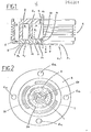
- 1 indicates the compressor head which lies, in the practice, on a cylinder which is not illustrated; the head body 2 encloses a ring-like cavity 3 which communicates with the open air or with a suitable vessel fitted with a filter (not shown), by means of known means, for instance a hole, which is also not shown.
- the head 1 is also provided with a cylindrical cavity 4, from which an adequate piping (not shown), which is screwed into the hole 5, leads the compressed fluid towards the storage tank.
- the head is also provided with four holes 6, suitable for fastening screws (not shown), which are designed to fix it onto the compressor cylinder.
- the head 1 houses a plate 8, which is locked to the body 2 of the said head and to the cylinder, herewith not shown, by means of the said fastening screws; to this purpose the plate 8 is provided with four holes 6a having coincident axes with the said holes 6.
- the plate 8 has three holes 7 which connect the ring-like space 3 with the compression chamber; it also has three holes 9, meant to connect the said compression chamber with the cavity 4.
- the three holes 7 are provided with appropriate slots which form a round circle having its centre in the central point 10 and are symmetrically located with respect to the centre 10;
- the three holes 9 are provided with appropriate slots which form a round circle having its centre on 10 and a smaller radius as compared to the afore-mentioned round circle; also these slot-shaped openings are symmetrical about.the centre 10; the three holes 9 end in a ring-like groove 21, which is to be found on the plate on the side of the said compression chamber.
- the plate 8 is provided with a central hole 10, suitable for a fastening screw 11 for the two disc-type valves 12 and 13, which are placed on the lower and upper surface of the plate 8, respectively; such hole 10 is fitted with traditional means to avoid any transfer of air to or from the cavity 4.
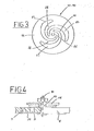
- the disc-type valves 12 and 13 illustrated in Fig. 3 are geometrically similar, but have a different size as the first valve 12 controls the three holes 7 and the second valve 13 controls the three holes 9.
- Said valves consist of an outer round crown 14, three slots 15, three ribs 16 and a central hole 17, for the fastening screw 11.
- the round crown 14 of valve 12 has an appropriate dimension so as to lie on the outlet ports of the three holes 7 on the lower side of the plate 8, in order to prevent the airfrom passing from the compression chamber to the cavity 3, but not vice-versa;
- the round crown 14 of valve 13 has an appropriate dimensions so as to lie on the outlet ports of the three holes 9, on the upper side of the plate 8, in order to prevent the air from passing from the cavity 4 to the compression chamber, but not vice-versa.
- the valve 12 is mounted in such way that the slots 15rest on the ring-like groove 21, so as to permit communication between the compression chamber and the holes 9, therefore the three slots 15 of the valve 12 have been made to the required size.
- the slots of the valve 13 form three ribs in the inner part of the same valve. The purpose of such ribs 16, in both valves, is to make them elastic so that the two crowns 14 of the valves 12 and 13, respectively, are driven away by pressure forces from the outlet ports of the holes 7 and 9 so as to connect the ring-like cavity 3 with the engine compression chamber and the latter with the cavity 4.
- valve 13 has a limited movement under the action of the pressure forces; for this reason a device as shown in Fig. 4 is used, which consists of a disc 18 mounted on a spacer hub 19; the said disc is fixed inside the cavity 4 and is held by the fastening screw 11.
- the compressor piston moves upwards; in the compression chamber a pressure is established,which causes the surface which is concerned by the force tomove in the direction of the arrow P; the result of this action on the members subject to elastic strain is the following: the valve 12 returns in the position A as shown in Fig. 1, thus closing the outlet ports of the holes 7; the valve 13 is bent in the position B 2 shown by a dotted line in Fig. 1, whereby the compression chamber can communicate with the cavity 4 which receives the air compressed by the piston; then the air flows through the hole 5.
- the purpose of the ring-like groove 21 is to call the air flow from the compression chamber towards the holes 9 and to avoid the build-up of possible deposits on the face of the plate 8 which is in contact with the valve 12.
- the two valves 12 and 13 open and close immediately under the action of the suction and compression forces, which cause on the ribs 16 elastic bending and torsional stresses which make the closing of the same valves even more rapid; the instantaneous opening and closing ensure higher mechanical efficiency of the compressor, as compared to the plates which use known valves, as little energy is required to move the valves 12 and 13 in the described directions.
- the fact of having restricted the clearance volumes to the holes 9 only means an increase of the volumetric efficiency as compared to the traditional compressors, since it eliminates the air volume which is pumped into the holes 7 without entering definitely into the compression chamber.
- the fact that the air flow has a coincident axis with the plate axis enables to obtain a reduction of the plate size and to increase the compressor efficiency, especially when the air outflow speeds are near to critical values.
- the valve working is very smooth; this eliminates any disturbing noise caused by the knocking of the valves against the seal surface and reduces remarkably the wear of the contact surfaces.
Landscapes
- Engineering & Computer Science (AREA)
- Mechanical Engineering (AREA)
- General Engineering & Computer Science (AREA)
- Compressor (AREA)
- Check Valves (AREA)
Applications Claiming Priority (2)
| Application Number | Priority Date | Filing Date | Title |
|---|---|---|---|
| IT347282 | 1982-06-30 | ||
| IT03472/82A IT1156620B (it) | 1982-06-30 | 1982-06-30 | Piastra valvolare per macchine alternative ed in particolare per compressori d'aria |
Publications (1)
| Publication Number | Publication Date |
|---|---|
| EP0100301A1 true EP0100301A1 (fr) | 1984-02-08 |
Family
ID=11108016
Family Applications (1)
| Application Number | Title | Priority Date | Filing Date |
|---|---|---|---|
| EP83830126A Withdrawn EP0100301A1 (fr) | 1982-06-30 | 1983-06-23 | Plaque à siège de soupape pour machines à piston, spécialement pour compresseurs d'air |
Country Status (2)
| Country | Link |
|---|---|
| EP (1) | EP0100301A1 (fr) |
| IT (1) | IT1156620B (fr) |
Cited By (2)
| Publication number | Priority date | Publication date | Assignee | Title |
|---|---|---|---|---|
| DE102014208639A1 (de) * | 2014-05-08 | 2015-11-12 | Robert Bosch Gmbh | Ventilanordnung |
| WO2020216531A1 (fr) * | 2019-04-26 | 2020-10-29 | Continental Reifen Deutschland Gmbh | Unité de compresseur servant à comprimer de l'air à l'intérieur de systèmes portatifs/transportables, utilisation d'une soupape à lames dans une telle unité de compresseur et système portatif/transportable servant à étanchéifier et gonfler des pneumatiques de véhicule |
Citations (3)
| Publication number | Priority date | Publication date | Assignee | Title |
|---|---|---|---|---|
| AT47158B (de) * | 1909-04-26 | 1911-03-27 | Conrad Gericke | Schnellaufende Verdichtungs- oder Verdünnungspumpe mit federnden Plattenventilen. |
| CH365171A (de) * | 1957-10-03 | 1962-10-31 | Carrier Corp | Kolbenkompressor mit Ventilaggregat |
| AT294295B (de) * | 1969-04-02 | 1971-11-10 | Bosch Gmbh Robert | Luftverdichter |
-
1982
- 1982-06-30 IT IT03472/82A patent/IT1156620B/it active
-
1983
- 1983-06-23 EP EP83830126A patent/EP0100301A1/fr not_active Withdrawn
Patent Citations (3)
| Publication number | Priority date | Publication date | Assignee | Title |
|---|---|---|---|---|
| AT47158B (de) * | 1909-04-26 | 1911-03-27 | Conrad Gericke | Schnellaufende Verdichtungs- oder Verdünnungspumpe mit federnden Plattenventilen. |
| CH365171A (de) * | 1957-10-03 | 1962-10-31 | Carrier Corp | Kolbenkompressor mit Ventilaggregat |
| AT294295B (de) * | 1969-04-02 | 1971-11-10 | Bosch Gmbh Robert | Luftverdichter |
Cited By (2)
| Publication number | Priority date | Publication date | Assignee | Title |
|---|---|---|---|---|
| DE102014208639A1 (de) * | 2014-05-08 | 2015-11-12 | Robert Bosch Gmbh | Ventilanordnung |
| WO2020216531A1 (fr) * | 2019-04-26 | 2020-10-29 | Continental Reifen Deutschland Gmbh | Unité de compresseur servant à comprimer de l'air à l'intérieur de systèmes portatifs/transportables, utilisation d'une soupape à lames dans une telle unité de compresseur et système portatif/transportable servant à étanchéifier et gonfler des pneumatiques de véhicule |
Also Published As
| Publication number | Publication date |
|---|---|
| IT8203472A0 (it) | 1982-06-30 |
| IT1156620B (it) | 1987-02-04 |
Similar Documents
| Publication | Publication Date | Title |
|---|---|---|
| US3947156A (en) | Diaphragm pump, particularly for the generation of vacuum | |
| US4978285A (en) | Reed valve for hermetic compressor | |
| US4834632A (en) | Compressor valve system | |
| US5147190A (en) | Increased efficiency valve system for a fluid pumping assembly | |
| US5603611A (en) | Piston type compressor with simple but vibration-reducing suction reed valve mechanism | |
| JPH0353477B2 (fr) | ||
| WO1993018304A1 (fr) | Compresseur hermetique | |
| US5577901A (en) | Compressor with valve unit for controlling suction and discharge of fluid | |
| US5266015A (en) | Compressor suction and discharge valve assembly | |
| KR880000987B1 (ko) | 압축기용 배출밸브 | |
| US8297957B2 (en) | Compressor | |
| KR20110013444A (ko) | 밀폐압축기용 방출밸브 장치 | |
| US4518323A (en) | Hermetic refrigeration compressor | |
| US5584676A (en) | Compressor discharge valve having a guided spherical head | |
| US4979879A (en) | Discharge system for rolling piston rotary compressor | |
| GB2333133A (en) | Compressor with recessed reed valve | |
| EP0100301A1 (fr) | Plaque à siège de soupape pour machines à piston, spécialement pour compresseurs d'air | |
| US4981421A (en) | Valve arrangement | |
| CA2099152C (fr) | Soupape de refoulement | |
| CA1304333C (fr) | Compresseur a soupape de refoulement comportant un element de retenue | |
| US5244364A (en) | Pumping unit | |
| US4173985A (en) | Straightway valve | |
| EP1116884B1 (fr) | Soupape d'admission d'un compresseur | |
| EP0144609A2 (fr) | Appareil à pompe à diaphragme | |
| US11913556B2 (en) | Anti-spin outer diameter guided compressor valve |
Legal Events
| Date | Code | Title | Description |
|---|---|---|---|
| PUAI | Public reference made under article 153(3) epc to a published international application that has entered the european phase |
Free format text: ORIGINAL CODE: 0009012 |
|
| AK | Designated contracting states |
Designated state(s): AT BE CH DE GB LI LU NL SE |
|
| STAA | Information on the status of an ep patent application or granted ep patent |
Free format text: STATUS: THE APPLICATION IS DEEMED TO BE WITHDRAWN |
|
| 18D | Application deemed to be withdrawn |
Effective date: 19841009 |
|
| RIN1 | Information on inventor provided before grant (corrected) |
Inventor name: PASQUALI, MARIO ALBERTO, DR. Inventor name: GRILLINI, MARCO, DR.-ING. |