EP0144609A2 - Appareil à pompe à diaphragme - Google Patents
Appareil à pompe à diaphragme Download PDFInfo
- Publication number
- EP0144609A2 EP0144609A2 EP84111969A EP84111969A EP0144609A2 EP 0144609 A2 EP0144609 A2 EP 0144609A2 EP 84111969 A EP84111969 A EP 84111969A EP 84111969 A EP84111969 A EP 84111969A EP 0144609 A2 EP0144609 A2 EP 0144609A2
- Authority
- EP
- European Patent Office
- Prior art keywords
- diaphragm
- cover
- operation chamber
- connecting rod
- frame
- Prior art date
- Legal status (The legal status is an assumption and is not a legal conclusion. Google has not performed a legal analysis and makes no representation as to the accuracy of the status listed.)
- Withdrawn
Links
Images
Classifications
-
- F—MECHANICAL ENGINEERING; LIGHTING; HEATING; WEAPONS; BLASTING
- F04—POSITIVE - DISPLACEMENT MACHINES FOR LIQUIDS; PUMPS FOR LIQUIDS OR ELASTIC FLUIDS
- F04B—POSITIVE-DISPLACEMENT MACHINES FOR LIQUIDS; PUMPS
- F04B43/00—Machines, pumps, or pumping installations having flexible working members
- F04B43/02—Machines, pumps, or pumping installations having flexible working members having plate-like flexible members, e.g. diaphragms
- F04B43/023—Machines, pumps, or pumping installations having flexible working members having plate-like flexible members, e.g. diaphragms double acting plate-like flexible member
Definitions
- the present invention relates to an improvement in a diaphragm type pump device.
- the diaphragm 2 is subjected to amplitude movement when the connecting rod 1 is reciprocatingly moved by a driving system (not shown).
- the volume of the operation chamber 6 increases as the connecting rod 1 is lowered in the direction of A and fluid is sucked from the intake port 7 through the check valve 9 in an opening state, while the check valve 10 is in a closing state.
- a diagram type pump device which comprises a connecting rod, a diaphragm connected to an end of the connecting rod, a cover which firmly secures the outer circumferential part of the diaphragm and constitutes a first operation chamber, a frame which opposes the cover to firmly secure the outer circumferential part of the diaphragm in association with the cover and constitutes a second operation chamber, and an intake port and a discharge port which are respectively communicated with the first operation chamber and the second operation chamber and provided with check valves each having different communicating direction, wherein the first and second operation chambers alternately perform pumping operation by the amplitude movement of the diaphragm due to a combination of the reciprocating movement of the connecting rod and the action of the check valves.
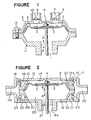
- a diaphragm type pump device of the present invention is generally constituted by a frame 19, a cover 13, a pair of end plates 25, 26, a diaphragm 2 fixed to the connecting rod 1 and check valves 17, 18, 23 and 24.
- the frame 19 has an insertion hole 19a through which the connecting rod extends upwardly so as to be movable by an external driving means.
- a sealing member 27 is provided at the insertion hole 19a to keep airtightness.
- the frame 19 also has an inner flange part 19b inwardly extends from the upper surface and two opposing openings 32, 33 are formed in the inner flange at positions near the upper surface of the frame 19.
- the cover 13 is placed opposing the frame 19 and has an inner flange 13a downwardly extending from the lower surface.
- Two opposing openings 30, 31 are formed in the inner flange 13a at positions near the lower surface of the cover 13.
- the outer circumferential part of the diaphragm 2, firmly secured at the top end of the connecting rod 1 by the nut 4, is clamped by opposing surfaces of the inner flanges of the cover 13 and the frame 19.
- a first operation chamber 14 is formed by the lower surface of the cover 13, the inner flange 13a and the diaphragm 2
- a second operation chamber 20 is formed by the upper surface of the frame 19, the inner flange 19b and the diaphragm 2.
- the end plates 25 and 26 are attached to openings formed at both sides of the cover 13 and the frame 19.
- the end plate 25 has an opening for intaking air and the end plate 26 has an opening for discharging air.
- the check valve 17 as a first check valve for intaking air is provided near the opening 30 to form a first intake port 15; the check valve 18 as a second check valve 18 is provided near the opening 31 to form a first discharge port 16; the check valve 23 as a third check valve is provided near the opening 32 to form a second intake port 21 and the check valve 24 as a fourth check valve is provided near the opening to form a second discharge port 22.
- the first and third check valves 17 and 23 act to only intake air and the second and fourth check valves 18 and 24 act to only discharge air.
- Reciprocating movement of the connecting rod 1 causes the amplitude movement of the diaphragm 2 as similar to the conventional device.
- the volume of the first operation chamber 14 increases as the connecting rod 1 is lowered in the direction of A, on account of which the first check valve 17 is opened and the second check valve is closed to thereby suck fluid through the first intake port 15.
- the volume of the second operation chamber 20 decreases whereby the fourth check valve 24 is opened and the third check valve 23 is closed with the consequence that the fluid in the second operation chamber 20 is discharged through the second discharge port 22.
- the first and second operation chambers 14, 20 alternately perform pumping operations by repeating the amplitude movement of the diaphragm.
- chambers formed at the upper and lower sides of a diaphragm is used as operation chambers for alternate pumping operations thereby obtaining a pump capacity of two times as much as the conventional device. It is, therefore, possible to miniaturize the shape of the pump while increasing its capacity in an economical manner. Further, pulsation of fluid can be remarkably reduced.
Landscapes
- Engineering & Computer Science (AREA)
- Mechanical Engineering (AREA)
- General Engineering & Computer Science (AREA)
- Reciprocating Pumps (AREA)
Applications Claiming Priority (2)
| Application Number | Priority Date | Filing Date | Title |
|---|---|---|---|
| JP159818/83U | 1983-10-14 | ||
| JP1983159818U JPS6066883U (ja) | 1983-10-14 | 1983-10-14 | ダイアフラム型ポンプ装置 |
Publications (2)
| Publication Number | Publication Date |
|---|---|
| EP0144609A2 true EP0144609A2 (fr) | 1985-06-19 |
| EP0144609A3 EP0144609A3 (fr) | 1986-12-03 |
Family
ID=15701915
Family Applications (1)
| Application Number | Title | Priority Date | Filing Date |
|---|---|---|---|
| EP84111969A Withdrawn EP0144609A3 (fr) | 1983-10-14 | 1984-10-05 | Appareil à pompe à diaphragme |
Country Status (2)
| Country | Link |
|---|---|
| EP (1) | EP0144609A3 (fr) |
| JP (1) | JPS6066883U (fr) |
Cited By (2)
| Publication number | Priority date | Publication date | Assignee | Title |
|---|---|---|---|---|
| WO2013171453A1 (fr) * | 2012-05-17 | 2013-11-21 | Selwood Group Limited | Pompe à membrane |
| US11002270B2 (en) * | 2016-04-18 | 2021-05-11 | Ingersoll-Rand Industrial U.S., Inc. | Cooling methods for electrically operated diaphragm pumps |
Families Citing this family (2)
| Publication number | Priority date | Publication date | Assignee | Title |
|---|---|---|---|---|
| KR101131922B1 (ko) | 2010-03-09 | 2012-04-03 | 강소대 | 상하부 챔버를 구비한 다이아프램 |
| GB201322103D0 (en) * | 2013-12-13 | 2014-01-29 | The Technology Partnership Plc | Fluid pump |
Family Cites Families (5)
| Publication number | Priority date | Publication date | Assignee | Title |
|---|---|---|---|---|
| US3461808A (en) * | 1967-07-03 | 1969-08-19 | Wood John Co | Diaphragm hand pumps |
| GB1263057A (en) * | 1968-02-22 | 1972-02-09 | Timothy James Francis Roach | Improvements in or relating to diaphragm pumps |
| CS169273B1 (fr) * | 1974-03-15 | 1976-07-29 | ||
| US4137020A (en) * | 1976-12-26 | 1979-01-30 | Nippondenso Co., Ltd. | Diaphragm type air pump |
| DE3140790A1 (de) * | 1981-10-14 | 1983-04-28 | Emil 4401 Laer Molzan | "bausatz fuer eine membranpumpe" |
-
1983
- 1983-10-14 JP JP1983159818U patent/JPS6066883U/ja active Pending
-
1984
- 1984-10-05 EP EP84111969A patent/EP0144609A3/fr not_active Withdrawn
Cited By (2)
| Publication number | Priority date | Publication date | Assignee | Title |
|---|---|---|---|---|
| WO2013171453A1 (fr) * | 2012-05-17 | 2013-11-21 | Selwood Group Limited | Pompe à membrane |
| US11002270B2 (en) * | 2016-04-18 | 2021-05-11 | Ingersoll-Rand Industrial U.S., Inc. | Cooling methods for electrically operated diaphragm pumps |
Also Published As
| Publication number | Publication date |
|---|---|
| EP0144609A3 (fr) | 1986-12-03 |
| JPS6066883U (ja) | 1985-05-11 |
Similar Documents
| Publication | Publication Date | Title |
|---|---|---|
| EP0033096B1 (fr) | Pompe à diaphragme | |
| US4749340A (en) | Piston type compressor with improved suction reed valve stopper | |
| US5577901A (en) | Compressor with valve unit for controlling suction and discharge of fluid | |
| US4666378A (en) | Diaphragm type pump device having a cushion member | |
| WO1993018304A1 (fr) | Compresseur hermetique | |
| JPH08226383A (ja) | コンプレッサ・真空ポンプ用リードバルブ | |
| EP0431753A1 (fr) | Pompe à mouvement alternatif | |
| US3645651A (en) | Pump | |
| CN101438059A (zh) | 压缩机 | |
| GB2068510A (en) | Compressor unit | |
| EP0144609A2 (fr) | Appareil à pompe à diaphragme | |
| KR0147004B1 (ko) | 왕복동형 압축기의 실린더장치 | |
| US3981631A (en) | Compressor head construction | |
| CN1255632C (zh) | 用于封闭式压缩机的汽缸装置 | |
| GB2037898A (en) | Reciprocating piston compressors | |
| US3811803A (en) | Diaphragm pump | |
| EP3260748A1 (fr) | Ensemble soupape | |
| CN210531109U (zh) | 水气混合微型泵及其设备 | |
| CN210531115U (zh) | 一体泵阀及其设备 | |
| EP0100301A1 (fr) | Plaque à siège de soupape pour machines à piston, spécialement pour compresseurs d'air | |
| CN216975183U (zh) | 一种微型泵及其隔膜装置 | |
| CN219197592U (zh) | 微型真空气泵 | |
| JPS5836867Y2 (ja) | ダイアフラムポンプ | |
| WO2019148004A1 (fr) | Pompe à cylindres flottants | |
| US765923A (en) | Air-compressor. |
Legal Events
| Date | Code | Title | Description |
|---|---|---|---|
| PUAI | Public reference made under article 153(3) epc to a published international application that has entered the european phase |
Free format text: ORIGINAL CODE: 0009012 |
|
| AK | Designated contracting states |
Designated state(s): DE FR GB |
|
| PUAL | Search report despatched |
Free format text: ORIGINAL CODE: 0009013 |
|
| AK | Designated contracting states |
Kind code of ref document: A3 Designated state(s): DE FR GB |
|
| STAA | Information on the status of an ep patent application or granted ep patent |
Free format text: STATUS: THE APPLICATION IS DEEMED TO BE WITHDRAWN |
|
| 18D | Application deemed to be withdrawn |
Effective date: 19870604 |
|
| PGFP | Annual fee paid to national office [announced via postgrant information from national office to epo] |
Ref country code: LU Payment date: 19900913 Year of fee payment: 7 |
|
| RIN1 | Information on inventor provided before grant (corrected) |
Inventor name: OGAWA, HITOSHI |