EP0100403B1 - Dispositif pour paraffiner un fil au moyen de paraffine solide - Google Patents
Dispositif pour paraffiner un fil au moyen de paraffine solide Download PDFInfo
- Publication number
- EP0100403B1 EP0100403B1 EP83104619A EP83104619A EP0100403B1 EP 0100403 B1 EP0100403 B1 EP 0100403B1 EP 83104619 A EP83104619 A EP 83104619A EP 83104619 A EP83104619 A EP 83104619A EP 0100403 B1 EP0100403 B1 EP 0100403B1
- Authority
- EP
- European Patent Office
- Prior art keywords
- thread
- paraffin body
- paraffin
- solid paraffin
- stop rail
- Prior art date
- Legal status (The legal status is an assumption and is not a legal conclusion. Google has not performed a legal analysis and makes no representation as to the accuracy of the status listed.)
- Expired
Links
Images
Classifications
-
- B—PERFORMING OPERATIONS; TRANSPORTING
- B65—CONVEYING; PACKING; STORING; HANDLING THIN OR FILAMENTARY MATERIAL
- B65H—HANDLING THIN OR FILAMENTARY MATERIAL, e.g. SHEETS, WEBS, CABLES
- B65H71/00—Moistening, sizing, oiling, waxing, colouring or drying filamentary material as additional measures during package formation
- B65H71/005—Oiling, waxing by applying solid wax cake during spooling
-
- B—PERFORMING OPERATIONS; TRANSPORTING
- B65—CONVEYING; PACKING; STORING; HANDLING THIN OR FILAMENTARY MATERIAL
- B65H—HANDLING THIN OR FILAMENTARY MATERIAL, e.g. SHEETS, WEBS, CABLES
- B65H2701/00—Handled material; Storage means
- B65H2701/30—Handled filamentary material
- B65H2701/31—Textiles threads or artificial strands of filaments
Definitions
- the present invention relates to a device for paraffin waxing a thread on spinning or winding machines with the aid of a paraffin body which resiliently rests against the thread path and at least one on a polygonal bolt which can be driven in rotation and whose axis is essentially perpendicular to the thread path between a delivery point and a winding device Stop rail is slidably mounted.
- a stop is arranged on one or both sides of the thread area on the end face of the paraffin body.
- the traversing angle is very limited by the stop or stops arranged to the side of the traversing area. If the thread is exceeded, the traverse reaches the area of the trapping or stops and thus impairs the paraffinizing process.
- the paraffin body is supported only over a partial length by the polygonal bolt which supports and drives it, so that it is reliably excluded that the polygonal bolt protrudes beyond the end face of the paraffin body and comes into contact with the yarn. Due to the own weight of the paraffin body, a tilting moment results, by which in particular a large paraffin body lowers with its side facing the yarn. The inner polygonal guide in the paraffin body is knocked out, so that the tilting movement becomes ever greater and the entrainment of the paraffin body by the polygonal bolt becomes worse and worse. In addition, this tilting moment is usually amplified by the stop or stops, which attack the bottom half of the face of the paraffin body during the most common thread movement from bottom to top.
- the object of the invention is therefore to design a paraffinizing device of the type mentioned at the outset in such a way that a uniform paraffinizing of the thread is ensured, in particular even in the case of large paraffin bodies.
- the stop rail extends transversely to the thread running direction and is arranged on the half of the face of the paraffin body facing away from the thread system side.
- the measure that the stop rail extends transversely to the thread running direction is prevented with certainty that the thread can temporarily adhere to the stop during its traversing movement, so that a consequent uneven application of paraffin on the thread is excluded. Since a hold of the thread by the stop is impossible due to its orientation, a single removal in the edge region of the front side while simultaneously leaving the central region of the front side of the paraffin body to stand cannot occur; In contrast, a uniform removal of the paraffin body is ensured over the entire surface of its face.
- the stop acts on the upper half of the paraffin body facing away from the thread system side, a counter torque is generated to the tilting moment generated by the dead weight. This counteracts a deflection of the drive guide of the paraffin body.
- the stop rail has a widened area that extends to the edge of the paraffin body. This widening increases the contact surface of the stop rail on that side of the thread run on which the thread is not in contact with the paraffin body anyway, and causes gentle sliding on the rotating paraffin body.
- the widening projects beyond the paraffin body on its circumference, so that the paraffin body can never come into contact with the outer edge of the stop rail.
- the areal widening is inclined towards the peripheral edge of the paraffin body.
- the stop rail is rounded on its side facing the polygonal bolt against the paraffin body. This slightly convex curvature causes the widening to lie flat on the paraffin body, but on the other hand, when the paraffin body rotates, no sharp edge of the stop rail can cut into the paraffin body, so that the contact between the paraffin body and the stop rail takes place extremely gently.
- a thread tension compensation bracket is provided, which is also designed as a stop rail, so that a separate thread tension compensation bracket is not required.
- a thread guide is arranged below the paraffin body and the stop rail is designed such that the thread lies essentially only on the lower half of the paraffin body on its end face.
- the stop rail is advantageously adjustable parallel to the longitudinal axis of the paraffin body. As a result, the deflection angle of the yarn on the paraffin body is changed, which also changes the contact pressure of the yarn fixed in its barrel.
- the stop rail can expediently be pivoted away from the area in front of the front side of the paraffin body, the stop rail advantageously having a thread catcher in order to remove the thread that is still running from the area in front of the end face of the paraffin body.
- the stop rail is assigned an elastic element by which it is pressed against the end face of the paraffin body. Accessibility to the paraffin body can also be improved in this way by simply folding away.
- the paraffin body is supported on a plate that can be tilted along the polygonal bolt, for which purpose the plate expediently has a guide hub on its side facing away from the paraffin body with an internal profile adapted to the shape of the polygonal bolt.
- the plate expediently has a guide hub on its side facing away from the paraffin body with an internal profile adapted to the shape of the polygonal bolt.
- the subject of the invention brings about an extremely uniform removal of the paraffin body, since it permanently occupies a precisely fixed position. This enables large paraffin bodies to be processed cost-effectively for the first time, which enables more economical production of the paraffin bodies and, moreover, more economical work during paraffinizing.
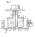
- the paraffinizing device arranged in the thread path between an active or passive delivery point and a winding device has a rotatable guide mandrel designed as a polygonal bolt 10, which is actuated by a suitable drive device 1 (FIG. 2), e.g. a motor or a suitably driven gear, can be rotated and on which a paraffin body 2 is placed.
- a suitable drive device 1 e.g. a motor or a suitably driven gear
- An active delivery point is to be understood here as a delivery point which feeds the thread 3 positively to the paraffin body 2, e.g. the spinning device of an open-end spinning device.
- a passive delivery point in the sense of this description, on the other hand, is a point from which the thread is withdrawn, e.g. the winding spool of a winding machine.
- a thread guide 4 which can also be formed by the pair of draw-off rollers in an open-end spinning device.
- the thread 3 is inserted into a traversing thread guide or a cross-groove roller, through which element the thread 3 is placed in a changing manner in a bobbin.
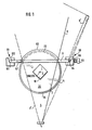
- the thread 3 covers a triangular surface during traversing, the so-called traversing triangle 5, which is limited by the running of the thread as shown and the running 3 'of the thread shown in dashed lines.
- the end face 20 of the paraffin body 2 is arranged in the traversing triangle 5 such that the paraffin body 2 projects beyond it laterally. This ensures that the iridescent thread 3 always rests on the end face 20 of the paraffin body 2.
- a stop designed as a stop rail 6 is assigned to the paraffin body 2 and limits the position of the paraffin body 2 in the direction of the running thread 3.
- the stop rail 6 extends transversely to the thread running direction and lies against the upper half of the end face 20 of the paraffin body 2.
- the stop rail 6 is mounted in a suitable manner on both sides of the paraffin body 2 in stationary holding devices 60 and 61.
- a compression spring 11 is supported, which the paraffin body 2 in System on the stop rail 6 holds.
- the thread 3 lies on its way from the delivery device to the winding device on the lower half of the end face 20 of the paraffin body 2, while it is on the upper half of the end face 20 of the paraffin body 2 facing away from the thread attachment side by the stop rail 6 is lifted off the paraffin body 2.
- the thread 3 passes through the end face 20 of the paraffin body 2, whereby it is oscillated back and forth in the area of the traversing triangle 5 by the traversing device (traversing thread guide or cross-groove roller), not shown.
- the traversing device traversing thread guide or cross-groove roller
- the thread 3 lies against the paraffin body 2 on the feed side thereof, while on the discharge side of the paraffin body 2 it is slightly lifted from the paraffin body 2 by the stop rail 6.
- the thickness of the selected stop rail 6 determines the length range of the thread course of the thread 3 on the end face 20 of the paraffin body 2.
- the thread 3 is not disturbed during its traversing movement by any stops or paraffin accumulations, so that a regular traversing of the thread 3 is also ensured in the area of the paraffin body 2. This also ensures uniform removal of the paraffin body 2. Since the thread 3 also cannot get stuck between the stop rail 6 and the paraffin body 3, since the stop rail 6 extends essentially transversely to the running of the oscillating thread 30 between the thread and the paraffin body 2, the end face 20 of the paraffin body 2, in which this is supported on the stop rail 6, uniform wear of the paraffin body 2 is achieved.
- the direction of the thread does not matter. While in the described embodiment the (active or passive) delivery point is below the paraffin body 2 and the winding device above it, so that the thread 3 passes through the paraffin body 2 from the bottom up, a reverse thread running direction is quite possible. In this case, the support rail 6 can still rest against the upper half of the end face 20 of the paraffin body 2, but the tip of the traversing triangle 5 formed by the thread guide 4 is located above the paraffin body 2 The advantage achieved is that the thread 3 is not jammed in the area of the stop rail 6, thereby achieving a uniform removal of the paraffin body 2.
- the thread guide 4 below the paraffin body 2 and the stop rail 6 are designed such that the thread essentially only on the lower half of the end face 20 of the paraffin body 2 is present.
- the rotation of the paraffin body 2 thus always acts on the thread 3 over the entire contact length of the thread 3 on the paraffin body 2 in the same direction - and not in the opposite direction as with longer contact lengths.
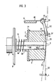
- the effect of a known paraffinizing device will be described with the aid of FIG. 3.
- the polygonal bolt 10 does not extend all the way to the end face 20 of the paraffin body 2, so that it cannot come into contact with the thread 3 that changes on the end face 20, which would prevent uniform waxing. Due to the weight of the paraffin body 2, it has the tendency to tilt downward on its unsupported end face 20, in particular since certain tolerances between the outer profile of the polygonal bolt 10 and the inner profile of the paraffin body 2 cannot be avoided. This tendency is further supported when the paraffin body 2 is supported on the lower half of its end face 20, as is the case in the prior art.
- the situation is different in the device described.
- the paraffin body 2 is always supported on the upper half of its end face 20, regardless of the direction of the thread, so that the paraffin body cannot tilt at all.
- the paraffin body 2 always assumes such a position that its longitudinal axis 200 coincides with the axis 100 of the polygonal bolt 10 (FIG. 2).
- This ensures a uniform drive of the paraffin body 2 even over long times and leads to a uniform removal of the paraffin body 2.
- This is of even greater importance in the case of open-end spinning devices than in the case of winding machines, since because of the lower winding speed of the thread 3 compared to that in winding machines
- Working time of a paraffin body 2 in open-end spinning devices is several times higher than in winding machines.
- the device described enables longer running times of the paraffin body 2, it also offers the prerequisite for larger dimensions of the paraffin body 2.
- This is also particularly advantageous in that in this way the contact length of the thread 3 on the end face 20 of the paraffin body 2, which is caused by the stop rail 6 extending transversely to the thread running direction has been somewhat shortened, can be enlarged again.
- the paraffin body 2 has a diameter of at least 50 mm.
- the paraffin body 2 thus has, for example, 5 times the mass and more than 5 times the service life of conventional paraffin body sizes.
- the tilting moment is of course also significantly greater than with small paraffin bodies 2. Even if the stop rail 6 certainly generates a sufficiently large counter torque, this is nevertheless bought with the disadvantage of an increased contact force and thus increased wear.
- the paraffin body 2 is supported on a plate 7 which can be displaced along the polygonal bolt and which has a guide hub 70 on its side facing away from the paraffin body 2 has an inner profile adapted to the outer profile of the polygonal bolt 10. This enables tilt-free displacement of the plate 7 on the polygonal bolt 10.
- the plate 7 counteracts the tilting moment of the paraffin body 2 in a safe manner, which is due to its own weight and the polygonal bolt 10 which does not extend over the full length of the faraffin body 2 is produced.
- This effect of the plate 7 is substantially supported by the largest possible contact surface for the faraffin body 2 and achieves its optimum if the plate 7 has an annular collar 71 on its circumference, which encompasses the paraffin body 2 slightly. In this way, the paraffin body 2 can be used for a particularly long working time; Even in the case of paraffinizing devices with other stops instead of the stop rail 6 described, such a tilt-free guided plate 7 is advantageous.
- the plate 7 it is not absolutely necessary for the plate 7 to have a guide hub 70 which projects beyond the plate base in the direction of the compression spring 11; with a corresponding thickness of the plate 7, this guide hub can also be omitted under certain circumstances if a tilt-free guiding of the plate 7 is ensured.
- the stop rail 6 lies as softly as possible on the paraffin body 2 in order to thereby contribute to its long service life.
- the stop rail 6 according to FIG. 1 has a flat widening 62 on its upper side, with which it rests on the paraffin body 2.
- the stop surface 63 of the stop rail 6 on the paraffin body 2 is enlarged and the pressure per unit area is correspondingly reduced at the same total system pressure.
- the widening 62 is achieved in a particularly simple manner in that the stop rail 6 with the widening 62 is formed as a continuous sheet.
- the sheet forming the stop rail 6 and the widening 62 projects somewhat beyond the paraffin body 2 on its peripheral edge 23 in the embodiment shown, so that the stop rail 6 has no edge in the area of the paraffin body 2 on its upper side.
- this stop surface 63 is slightly convex towards its lower end, ie the stop rail is rounded on its side facing the polygonal bolt 10 against the paraffin body 2, so that here too it is effectively prevented that an edge can cut into the end face 20 of the paraffin body 2.
- the contact pressure of the wax body 2 against the thread 3 can be changed.
- the plane of the traversing triangle 5 of the thread 3 is, however, defined by the thread guide 4 and the stop rail 6 which effects a thread deflection.
- the latter is displaced parallel to its longitudinal axis 200, so that the thread deflection at the lower peripheral edge 24 of the paraffin body 2 is also increased or decreased.
- the paraffin body 2 is fixed in its respective axial position by adjusting the stop rail 6 parallel to the longitudinal axis 200 of the paraffin body 2.
- the stop rail 6 has an end 64 and 65 bent on both sides parallel to the longitudinal axis 200 of the paraffin body 2 , with the help of which the stop rail 6 is mounted in the holding devices 60 and 61.
- One end 64 has a plurality of circumferential grooves 640 arranged one behind the other, with which a locking bolt 66 elastically mounted in the holding device 60 cooperates.
- the stop rail 6 By partially pulling out the locking pin 66, the stop rail 6 can be adjusted by one or more circumferential grooves in one direction or the other parallel to the longitudinal axis 200 of the paraffin body 2, whereupon the stop rail 6 can be returned to its new position by releasing the locking pin 66 is secured.
- Other attachments are of course also possible.
- the mounting of the end 65 in the holding device 61 is designed as an upwardly open groove 610.
- the stop rail 6 in order to remove the thread 3 from the end face 20 of the paraffin body 2 at the same time without the thread withdrawal having to be interrupted, the stop rail 6 in the embodiment shown has a thread catcher 67 which reaches the area of the thread 3 sliding along the stop rail 6 and takes the thread 3 with it when the stop rail 6 is pivoted into the rest position 6 '.
- paraffinised yarn is mainly used in knitting and knitting, where the thread 3 is guided by thread guides before reaching the stitch-forming parts.
- a paraffin film is deposited over time, which ensures sufficient sliding and post-waxing of the thread 3 in the case of non-waxed thread sections.
- pivot axis 68 of the stop rail 6 it is not absolutely necessary for the pivot axis 68 of the stop rail 6 to run parallel to the longitudinal axis 200 of the paraffin body 2. Rather, it is also possible to provide a vertical pivot axis, so that the pivot plane is arranged parallel to the longitudinal axis 200 of the paraffin body 2.
- a thread catcher 67 can also be provided here, as can the possibility of adjusting the stop rail 6 parallel to the longitudinal axis 200 of the paraffin body 2, for example by the holding devices 60 and 61 being adjustably mounted in this direction. It is also possible to provide the pivot axis parallel to the plane 22 through the end face 20 of the paraffin body 2. Such a modification of the described device is shown in FIG. 3, which shows the pivot axis 69 of the stop rail 6 above the paraffin body 2.
- this spring plate 80 also provides an elastic support for the paraffin body 2 by the stop rail 6.
- the stop rail 6 can undergo further modifications. For example, it is possible to design these as thread tension compensation brackets. With appropriate guidance of the thread over the stop rail 6, this can take over the task of a thread tension compensation bracket, so that a separate thread tension compensation bracket is unnecessary.
- the size of the paraffin body 2 to be processed is in principle irrelevant to the present invention, but its use is particularly advantageous for large diameters of 50 mm or more.
Landscapes
- Chemical & Material Sciences (AREA)
- Oil, Petroleum & Natural Gas (AREA)
- Treatments For Attaching Organic Compounds To Fibrous Goods (AREA)
- Spinning Or Twisting Of Yarns (AREA)
- Treatment Of Fiber Materials (AREA)
Claims (9)
Applications Claiming Priority (2)
| Application Number | Priority Date | Filing Date | Title |
|---|---|---|---|
| DE3228642A DE3228642C2 (de) | 1982-07-31 | 1982-07-31 | Vorrichtung zum Paraffinieren eines Fadens an Spinn- oder Spulmaschinen mit Hilfe eines festen Paraffinkörpers |
| DE3228642 | 1982-07-31 |
Publications (2)
| Publication Number | Publication Date |
|---|---|
| EP0100403A1 EP0100403A1 (fr) | 1984-02-15 |
| EP0100403B1 true EP0100403B1 (fr) | 1986-01-15 |
Family
ID=6169802
Family Applications (1)
| Application Number | Title | Priority Date | Filing Date |
|---|---|---|---|
| EP83104619A Expired EP0100403B1 (fr) | 1982-07-31 | 1983-05-11 | Dispositif pour paraffiner un fil au moyen de paraffine solide |
Country Status (7)
| Country | Link |
|---|---|
| US (1) | US4501221A (fr) |
| EP (1) | EP0100403B1 (fr) |
| DE (1) | DE3228642C2 (fr) |
| GB (1) | GB2127048B (fr) |
| HK (1) | HK7887A (fr) |
| MY (1) | MY8700327A (fr) |
| SG (1) | SG87586G (fr) |
Families Citing this family (10)
| Publication number | Priority date | Publication date | Assignee | Title |
|---|---|---|---|---|
| DE3422814A1 (de) * | 1984-06-20 | 1986-01-02 | Schubert & Salzer Maschinenfabrik Ag, 8070 Ingolstadt | Antriebsvorrichtung fuer eine paraffiniereinrichtung |
| DE3910917A1 (de) * | 1989-04-05 | 1990-10-11 | Schubert & Salzer Maschinen | Vorrichtung zur behandlung von paraffinkoerpern |
| DE4434566C2 (de) * | 1994-09-28 | 2002-07-18 | Rieter Ingolstadt Spinnerei | Paraffiniereinrichtung |
| US5520351A (en) * | 1995-01-31 | 1996-05-28 | Johnson & Johnson Consumer Products, Inc. | Heated thread tensioner assembly |
| MXPA05001839A (es) * | 2002-08-15 | 2005-04-19 | Binder Siegfried | Anillo de parafina para parafinar hilos. |
| DE10354588B4 (de) * | 2003-11-21 | 2014-02-20 | Saurer Germany Gmbh & Co. Kg | Paraffiniereinrichtung für eine Kreuzspulen herstellende Textilmaschine |
| DE102006018838B4 (de) * | 2005-06-22 | 2012-09-20 | Oerlikon Textile Gmbh & Co. Kg | Paraffiniereinrichtung für eine Kreuzspulen herstellende Textilmaschine |
| DE102007018650A1 (de) * | 2007-04-21 | 2008-10-23 | Oerlikon Textile Gmbh & Co. Kg | Paraffiniereinrichtung für eine Arbeitsstelle einer Kreuzspulen herstellenden Textilmaschine |
| DE102014012247A1 (de) * | 2014-08-19 | 2016-02-25 | Saurer Germany Gmbh & Co. Kg | Paraffiniereinrichtung für eine Kreuzspulen herstellende Textilmaschine |
| DE102016120083A1 (de) * | 2016-10-21 | 2018-04-26 | Saurer Germany Gmbh & Co. Kg | Auflaufspulen herstellende Textilmaschine mit einer Paraffiniereinrichtung |
Family Cites Families (6)
| Publication number | Priority date | Publication date | Assignee | Title |
|---|---|---|---|---|
| US1350007A (en) * | 1919-11-14 | 1920-08-17 | Cunningham Thomas | Yarn-waxing device |
| BE694730A (fr) * | 1967-02-28 | 1967-07-31 | ||
| US3479988A (en) * | 1967-06-26 | 1969-11-25 | Barber Colman Co | Running thread waxer |
| DE2105558B2 (de) * | 1971-02-06 | 1976-11-11 | Elitex - Zavody Textilniho Strojirenstvi Generalni Reditelstvi, Reichenberg (Tschechoslowakei) | Vorrichtung zum paraffinieren von garn |
| IT1037277B (it) * | 1975-04-14 | 1979-11-10 | Nuova S Giorgio Spa | Dispositivo per paraffinare il filato |
| DE7927734U1 (de) * | 1979-09-29 | 1980-01-03 | Schubert & Salzer Maschinenfabrik Ag, 8070 Ingolstadt | Vorrichtung zum Paraffinieren von Garn |
-
1982
- 1982-07-31 DE DE3228642A patent/DE3228642C2/de not_active Expired
-
1983
- 1983-05-11 EP EP83104619A patent/EP0100403B1/fr not_active Expired
- 1983-06-23 GB GB08317033A patent/GB2127048B/en not_active Expired
- 1983-07-14 US US06/513,996 patent/US4501221A/en not_active Expired - Fee Related
-
1986
- 1986-10-31 SG SG875/86A patent/SG87586G/en unknown
-
1987
- 1987-01-22 HK HK78/87A patent/HK7887A/xx unknown
- 1987-12-30 MY MY327/87A patent/MY8700327A/xx unknown
Also Published As
| Publication number | Publication date |
|---|---|
| GB2127048B (en) | 1985-12-04 |
| EP0100403A1 (fr) | 1984-02-15 |
| HK7887A (en) | 1987-01-28 |
| MY8700327A (en) | 1987-12-31 |
| DE3228642A1 (de) | 1984-02-09 |
| US4501221A (en) | 1985-02-26 |
| GB2127048A (en) | 1984-04-04 |
| GB8317033D0 (en) | 1983-07-27 |
| SG87586G (en) | 1987-03-27 |
| DE3228642C2 (de) | 1985-02-21 |
Similar Documents
| Publication | Publication Date | Title |
|---|---|---|
| DE3202428C2 (de) | Verfahren und Vorrichtung zum Anspinnen eines Fadens in einer Offenend-Spinnvorrichtung | |
| EP3891089B1 (fr) | Dispositif et procédé d'enroulement d'un fil | |
| EP1902990B1 (fr) | Dispositif pour une machine de prétraitement de filature | |
| EP0100403B1 (fr) | Dispositif pour paraffiner un fil au moyen de paraffine solide | |
| CH636651A5 (de) | Vorrichtung an einer spinnmaschine zum einwachsen eines garnes. | |
| DE102006018838B4 (de) | Paraffiniereinrichtung für eine Kreuzspulen herstellende Textilmaschine | |
| EP0411382B1 (fr) | Dispositif de préparation pour dévider l'extrémité de fil dans le bout du fuseau | |
| EP1178000A2 (fr) | Dispostif de bobinage pour une machine textile qui produit des bobines à spires croisées | |
| EP0036066B1 (fr) | Dispositif pour interrompre l'arrivée du ruban de fibres d'un dispositif à filer à bout libéré | |
| EP0593951A2 (fr) | Dispositif de filature | |
| EP1182284A2 (fr) | Métier à filer à bout libre, et procédé pour enrouler un fil temporairement à l'aide de tel métier | |
| DE2705660C3 (de) | Offenend-Spinnmaschine mit einer Vorrichtung zum Wickeln von Kreuzspulen | |
| DE4334813B4 (de) | Spulvorrichtung | |
| EP3321222B1 (fr) | Poste de travail d'une machine textile fabriquant des bobines croisées avec un dispositif de stockage du fil mécanique disposé dans la zone d'un dispositif de déplacement de fil en va-et-vient | |
| DE2939875C3 (de) | Einschaltevorrichtung an einer Einrichtung zum zeitweiligen Abziehen von Schußgarn von einer ortsfesten Vorratsspule einer Webmaschine | |
| DE3123282C1 (de) | Vorrichtung zur Aufnahme eines Fadens von einer Spule und UEbergabe an ein Arbeitsorgan | |
| CH631413A5 (de) | Vorrichtung zum aufspulen textiler faeden. | |
| EP0182241B1 (fr) | Dispositif pour la filature à friction | |
| DE3042957A1 (de) | Fadenliefervorrichtung | |
| DE102016104601A1 (de) | Textilmaschine mit einer kontinuierlichen Lieferung des erzeugten Garns und Garnaufwicklung auf eine kreuzgewickelte Kegelspule | |
| EP3331790B1 (fr) | Dispositif de remplissage d'un pot de filature avec un ruban de fibres | |
| WO1993010291A1 (fr) | Banc d'etirage pour machine a filer en fin, en particulier pour machine a filer a filiere | |
| CH669776A5 (fr) | ||
| DE3416804A1 (de) | Einrichtung zur rueckfuehrung von garn | |
| AT162672B (de) | Sägeschränkvorrichtung |
Legal Events
| Date | Code | Title | Description |
|---|---|---|---|
| PUAI | Public reference made under article 153(3) epc to a published international application that has entered the european phase |
Free format text: ORIGINAL CODE: 0009012 |
|
| AK | Designated contracting states |
Designated state(s): CH FR IT LI |
|
| ITCL | It: translation for ep claims filed |
Representative=s name: ZINI MARANESI |
|
| EL | Fr: translation of claims filed | ||
| 17P | Request for examination filed |
Effective date: 19840216 |
|
| ITF | It: translation for a ep patent filed | ||
| GRAA | (expected) grant |
Free format text: ORIGINAL CODE: 0009210 |
|
| AK | Designated contracting states |
Designated state(s): CH FR IT LI |
|
| ET | Fr: translation filed | ||
| PLBI | Opposition filed |
Free format text: ORIGINAL CODE: 0009260 |
|
| R20 | Corrections of a patent specification |
Effective date: 19860407 |
|
| 26 | Opposition filed |
Opponent name: W. SCHLAFHORST & CO. Effective date: 19861002 |
|
| PLBN | Opposition rejected |
Free format text: ORIGINAL CODE: 0009273 |
|
| STAA | Information on the status of an ep patent application or granted ep patent |
Free format text: STATUS: OPPOSITION REJECTED |
|
| 27O | Opposition rejected |
Effective date: 19880305 |
|
| PGFP | Annual fee paid to national office [announced via postgrant information from national office to epo] |
Ref country code: FR Payment date: 19910508 Year of fee payment: 9 |
|
| ITTA | It: last paid annual fee | ||
| PGFP | Annual fee paid to national office [announced via postgrant information from national office to epo] |
Ref country code: CH Payment date: 19910620 Year of fee payment: 9 |
|
| PG25 | Lapsed in a contracting state [announced via postgrant information from national office to epo] |
Ref country code: LI Effective date: 19920531 Ref country code: CH Effective date: 19920531 |
|
| PG25 | Lapsed in a contracting state [announced via postgrant information from national office to epo] |
Ref country code: FR Effective date: 19930129 |
|
| REG | Reference to a national code |
Ref country code: CH Ref legal event code: PL |
|
| REG | Reference to a national code |
Ref country code: FR Ref legal event code: ST |