EP0100494A1 - Dispositif d'alimentation en cigarettes ou analogues pour une machine d'empaquetage - Google Patents
Dispositif d'alimentation en cigarettes ou analogues pour une machine d'empaquetage Download PDFInfo
- Publication number
- EP0100494A1 EP0100494A1 EP83107144A EP83107144A EP0100494A1 EP 0100494 A1 EP0100494 A1 EP 0100494A1 EP 83107144 A EP83107144 A EP 83107144A EP 83107144 A EP83107144 A EP 83107144A EP 0100494 A1 EP0100494 A1 EP 0100494A1
- Authority
- EP
- European Patent Office
- Prior art keywords
- cigarette
- cigarettes
- conveyor
- well
- packaging machine
- Prior art date
- Legal status (The legal status is an assumption and is not a legal conclusion. Google has not performed a legal analysis and makes no representation as to the accuracy of the status listed.)
- Granted
Links
- 235000019504 cigarettes Nutrition 0.000 title claims abstract description 186
- 238000004806 packaging method and process Methods 0.000 title claims abstract description 27
- 230000004888 barrier function Effects 0.000 claims description 12
- 230000008859 change Effects 0.000 claims description 3
- 230000005540 biological transmission Effects 0.000 claims 1
- 230000009467 reduction Effects 0.000 abstract description 2
- 230000000694 effects Effects 0.000 description 7
- 210000000056 organ Anatomy 0.000 description 5
- 230000007704 transition Effects 0.000 description 3
- 238000004519 manufacturing process Methods 0.000 description 2
- 238000011144 upstream manufacturing Methods 0.000 description 2
- 238000010276 construction Methods 0.000 description 1
- 230000008878 coupling Effects 0.000 description 1
- 238000010168 coupling process Methods 0.000 description 1
- 238000005859 coupling reaction Methods 0.000 description 1
- 230000003247 decreasing effect Effects 0.000 description 1
- 230000009191 jumping Effects 0.000 description 1
- 230000008719 thickening Effects 0.000 description 1
Images




Classifications
-
- A—HUMAN NECESSITIES
- A24—TOBACCO; CIGARS; CIGARETTES; SIMULATED SMOKING DEVICES; SMOKERS' REQUISITES
- A24C—MACHINES FOR MAKING CIGARS OR CIGARETTES
- A24C5/00—Making cigarettes; Making tipping materials for, or attaching filters or mouthpieces to, cigars or cigarettes
- A24C5/35—Adaptations of conveying apparatus for transporting cigarettes from making machine to packaging machine
- A24C5/352—Adaptations of conveying apparatus for transporting cigarettes from making machine to packaging machine using containers, i.e. boats
- A24C5/356—Emptying the boats into the hopper of the packaging machine
-
- A—HUMAN NECESSITIES
- A24—TOBACCO; CIGARS; CIGARETTES; SIMULATED SMOKING DEVICES; SMOKERS' REQUISITES
- A24C—MACHINES FOR MAKING CIGARS OR CIGARETTES
- A24C5/00—Making cigarettes; Making tipping materials for, or attaching filters or mouthpieces to, cigars or cigarettes
- A24C5/35—Adaptations of conveying apparatus for transporting cigarettes from making machine to packaging machine
Definitions
- the invention relates to a device for supplying cigarettes or the like.
- a packaging machine the cigarettes being delivered in batches, in particular in cigarette containers (trays) which are turned down for emptying with an upper opening side in such a way that the cigarettes or. Run out under their own weight from the cigarette container to form an uninterrupted flow of cigarettes from cigarettes oriented transversely to the transport direction in a parallel position, which are fed by conveyors between lateral boundaries (side walls) of the packaging machine.
- the invention is based on the above or a similar device for feeding cigarettes to a packaging machine or the like.
- the object on which the invention is based is to improve the flow of cigarettes and at the same time to make the device simpler in construction and less prone to failure.
- the device according to the invention is characterized in that a cigarette cover is arranged above the cigarette stream at least in a partial area thereof, which (Upper) contours of the stream of cigarettes is adjustable.
- the cigarette cover according to the invention can be designed in various ways, preferably consists of a chain of (rotatable) rolls lined up.
- the cigarette cover lies under its own weight on the top of the cigarette stream, adapting to the changing heights of the cigarette stream.
- the cigarette cover ensures that the cigarettes arranged one above the other within the cigarette stream and oriented parallel and transversely to the conveying direction maintain this relative position during transport. In addition, the transport of a relatively voluminous flow of cigarettes is ensured by the cigarette cover.
- the rotatable mounting of the rolls prevents the cigarettes from jumping over.
- the cigarette cover ensures that the lower cigarettes, and thus the entire cigarette stream, are carried along gently and smoothly by the conveyor.
- the cover also creates a continuous, uninterrupted stream of cigarettes due to clinging of the cigarettes within the cigarette stream due to the low pressure.
- a particularly expedient embodiment is one in which a conveyor (discharge conveyor) facing the packaging machine is driven continuously, and preferably at a constant conveying speed.
- An upstream intermediate conveyor is also continuously driven in the sense of this solution, but at different speeds, namely at a reduced speed, if the adjacent receiving conveyor is currently switched off due to an interrupted cigarette supply.
- movement organs or compensating bodies which are arranged within the cigarette stream, in particular below the respective emptied tray.
- These movement organs are bodies with a special geometric shape, namely conical or truncated cone-shaped lateral surfaces.
- the relative arrangement is such that a converging position of the cigarette in the region of a filter mouthpiece is compensated for by the slight thickening of the cigarettes.
- the movement members are driven to rotate, the axis of rotation being slightly offset from the longitudinal central axis, so that slight sideways movements are carried out.
- the exemplary embodiment shown relates specifically to the loading of a packaging machine with cigarettes 10. These are each delivered in larger batches in a special cigarette container, namely in a tray 11.
- the cigarettes 10 can be removed from the tray via an opening side 12 originally pointing upwards. This is downward in the arrangement shown in FIG. 1 directed, since the cigarettes 10 are removed from the tray 11 by reversing the same.
- the tray 11 is arranged on an elongated, essentially rectangular intermediate container 13, specifically in the area of a feed opening 14 thereof.
- the intermediate container 13 is otherwise delimited by an upper wall 15, by end walls 16 and 17 extending at the ends, by side walls 18 and 19 and below by conveyors (belt straps).
- the upper wall 15 defines the supply opening 14 with the adjacent end wall 17.
- the cigarettes are removed from the intermediate container 13 on the approximately diagonally opposite lower side, specifically in the region of an outlet opening 20 formed in the lower level of the intermediate container 13.
- a special feature of the present exemplary embodiment is that the intermediate container 13 takes over the function of an otherwise usual cigarette magazine.
- essentially upright cigarette chutes 21 are formed in the region of the outlet opening 20, which converge downwards in the usual manner and between which wedge-shaped shaft walls 27 are arranged.
- cigarette groups assigned to a cigarette pack are removed in a known manner. In the present exemplary embodiment, two groups of such cigarette chutes 21 are formed.
- the lower boundary or the bottom of the intermediate container 13 form (outside the region of the outlet opening 20) three conveyors, namely a receiving conveyor 22, a discharge conveyor 23 and one intermediate conveyor 24 arranged therebetween.
- the receiving conveyor 22 extends to the end wall 17 and thus below the feed opening 14.
- the shorter conveyor 23, in contrast, is immediately adjacent to the outlet opening 20.
- the relatively shorter intermediate conveyor is arranged between the two.
- the transitions between the conveyors are formed by short stationary bridges 25.
- the conveyors 22, 23 and 24 extend over the full width of the intermediate container 13, that is to say at least from one side wall 18, 19 to the other.
- the intermediate container 13 serves to hold the cigarettes after removal from the tray 11 until they are taken over to the cigarette shafts 21 or to any further conveyor. Furthermore, the intermediate container 13 has the function of a store, with the aim of ensuring a constant, uninterrupted supply of cigarettes when the same is delivered discontinuously (in slants). During the exchange of an emptied slope 11 for a filled one, the transfer of the cigarettes to the packaging machine should continue. For this purpose, a sufficient cigarette supply is built up within the intermediate container 13, specifically by forming an uninterrupted stream of cigarettes 26 extending from the feed opening 14 to the outlet opening 20. This flow is fed to the outlet opening 20 by the conveyors as the height changes.
- the conveyors 22, 23 and 24 are driven in a special way and differently.
- all conveyors are driven, with increasing in the direction of transport Speed. Accordingly, the receiving conveyor 22 runs at the lowest speed, the intermediate conveyor 24 has a higher speed and the discharge conveyor 23 runs at the highest conveying speed.
- belt speeds For the conveyance of, for example, about 8000 cigarettes per minute, belt speeds of 3.2 m / sec. (Conveyor 23), 2.8 m / sec. (Intermediate conveyor 24) and 2 m / sec. (Receiving conveyor 22) useful.
- the increasing belt speed enables the entire amount of cigarettes flowing down from the tray 11 to be conveyed away by deflecting by 90 ° in the direction of the cigarette stream 26 there is a relatively lower level of the cigarette stream 26.
- the intermediate conveyor 24 is, however, driven at a reduced speed, e.g. with the same as the (running) receiving conveyor 22, z.3. thus 2 m / sec.
- the intermediate conveyor 24 has the main function of forming a transition stage in the transport route of the cigarettes. It is thereby possible to transfer the cigarettes gently from the relatively low conveying speed of the receiving conveyor 22 to the comparatively high conveying speed of the conveying conveyor 23. While the receiving conveyor 22 is at a standstill, the transition is also brought about by the intermediate conveyor 24 running at a lower speed.
- the conveyors or their conveyor belts are designed differently tet.
- the receiving conveyor 22 and the removal conveyor 23 are preferably designed in the sense of FIG. 3 with a surface design which improves the transport effect, for example with sawtooth-like, transverse ribs 28.
- the surface of the intermediate conveyor 24, on the other hand, is expediently designed to have a smooth surface.
- the (three) conveyors are driven by two drive motors 29 and 30. In the present case, these are mounted above the intermediate container 13, namely above the upper wall 15. Drive wheels 33, 34, 35 and 36 in the deflection area of the conveyors are driven via drive chains 31 and 32, respectively.
- the drive motor 29 is assigned once to the drive wheel 33 for the removal conveyor 23 and also to a drive wheel 34 of the intermediate conveyor.
- the drive motor 30 is connected to the drive wheel 36 of the receiving conveyor 22 and moreover to a further drive wheel 35 of the intermediate conveyor 24.
- the drive wheels 34 and 35 of the intermediate conveyor 24 are mounted on a common drive shaft 37 of the intermediate conveyor 24.
- the connection between the drive wheels 34 and 35, on the one hand, and the drive shaft 37, on the other hand, is such that, alternatively, one or the other drive motor 29 or 30 comes into effect for the intermediate conveyor 24.
- the drive motor 29 for the conveyor 23 is constantly driven - apart from exceptional interruptions. As a result, the discharge conveyor 23 is also continuously driven.
- a driving force is also continuously transmitted to the intermediate conveyor 24 by the drive motor 29, but at a lower speed due to the correspondingly dimensioned drive wheel 34 assigned to the drive motor 29. These therefore comes into effect when the drive motor 30 is stopped.
- the intermediate conveyor 24 is now driven by the drive motor 29 at the reduced speed.
- the receiving conveyor 22 is driven on the one hand, and the intermediate conveyor 24 is also driven at an increased speed by the appropriate dimensioning of the drive wheel 35 assigned to the drive motor 30.
- the drive via the drive wheel 34 is now ineffective, so that the Intermediate conveyor 24 rotates at the higher speed.
- the drive wheels 34 and 35 are connected to one another by a one-way clutch 38. This can be designed in a known manner and designed so that the faster drive movement (drive motor 30 via drive wheel 35) comes into effect, the further rotating drive wheel 34 being "overhauled".
- the drive motor 30 is currently switched off for the tray change in the manner described.
- the described coupling of the intermediate conveyor 24 to the drive of the receiving conveyor 22 and the discharge conveyor 23 ensures that the intermediate conveyor always has the optimum speed for conveying the cigarettes.
- the described transport device for the cigarette stream 26 brings about an uninterrupted supply to the packaging machine by delivering sufficient quantities of cigarettes in the area of the outlet opening 20.
- its "depth" is considerably weakened by the effect of the intermediate conveyor 24 in particular, so that a largely uniform cigarette flow 26, namely with slight fluctuations in height - but with an intentionally decreasing height - is produced.
- the conveyors are particularly effective when a cigarette cover 40 is arranged on the top of the cigarette stream 26.
- This has the task of maintaining the orderly orientation of the cigarettes 10 transversely to the conveying direction and parallel to one another during transport and the relative movements caused thereby.
- the cigarette cover 40 ensures proper transport due to the small, finely metered weight with which it rests on the cigarette stream 26 without impairing the cigarettes.
- the cigarette cover 40 can be closely fitted to the contours of the cigarette stream 26.
- the cigarette cover 40 in the present exemplary embodiment consists of a number of rollers 41 which are pivotally or articulatedly connected to one another. These are likewise arranged transversely to the direction of transport, namely axially parallel to the cigarettes 10. Each roller 41 can be rotated about its own longitudinal axis, which means the transport of the cigarettes 10 is favored.
- the rollers 41 are equipped with ball bearings 60.
- connecting straps 43 and 44 connect to the adjacent rolls on both sides.
- the connecting straps 43 and 44 are rotatably or pivotably mounted on the roller axles 42, so that a link chain with high mobility is created.
- the roller jacket 61 of the roller 41 is slidably rotatably mounted on a collar 63 on the roller axis 42.
- the cigarette cover 27 designed in this way is also adapted in terms of its dimensions to that of the cigarettes 10.
- the distance between the roller shells 61 from each other is about 2 mm.
- the diameter of the rolls or the roll jackets is dimensioned to approximately 16 mm. This results in a center distance of 18 mm, all taking into account an 8 mm diameter of the cigarettes.
- the aforementioned dimensions ensure that the cigarettes 10 do not enter a gap between adjacent rolls 41 and wedge here. Rather, the cigarettes are moved past the rollers 41 during the relative movement while rotating them. A certain, slight braking effect is exerted on the cigarette stream 26. Furthermore, the contact pressure generated by the cigarette cover 27 on the cigarette stream 26 is selected so that it is carried along by the conveyor in the event of slight slippage. The pressure function is the main task of the cigarette cover. It therefore extends essentially over the entire Conveying path of the cigarettes, that is to say over the length of the conveying stream 26.
- the entire length of the rolls 41 is adapted to the width of the intermediate container 13 in such a way that the cigarette cover 40 fits - with a small gap - between the side walls 18 and 19 can.
- Rounded heads 64 can rest against the side walls 18, 19.
- the cigarettes 10 have approximately the same length and are therefore also conveyed along the side walls 18, 19 with a small distance between their ends.
- the cigarette cover 40 is anchored at the edge of the feed opening 14 on the one hand and above the outlet opening 20, namely on the side wall 19.
- the latter anchorage can be moved up and down in a guide rail 45.
- the cigarette cover 40 accordingly extends over almost the full length and width of the cigarette stream 26.
- the level of the cigarette level within the intermediate container 13 is constantly checked, namely in the area of the cigarette supply and in the area of the transfer to the packaging machine.
- two light barriers 47, 49 running transversely to the longitudinal direction of the cigarettes 10 are arranged above the outlet opening 20.
- the upper light barrier 47 monitors the maximum level of the cigarettes 10 in the intermediate container 13 by stopping the discharge conveyor 23 (or one of the upstream conveyors) as soon as the cigarette flow 26 rises to the light barrier 47.
- the minimum level is monitored by the light barrier 49, which acts on the packaging machine downstream of the cigarette shaft 21, not shown in the figures, in such a way that it is stopped as soon as the supply of the cigarettes 10 becomes too low.
- a further light barrier 46 across a partial region of the conveying path transverse to the longitudinal direction of the cigarettes 10 formed to monitor the maximum amount of cigarette stream 26 in this area.
- a second, transverse light barrier 48 (acting in the longitudinal direction of the cigarettes) extends below the light barrier 46. This serves to monitor a minimum permissible cigarette level in the cigarette stream 26.
- the light barrier 46 acts on the drive motor 30 in the sense of stopping the same, so that the further cigarette supply is interrupted.
- the light barrier 48 is assigned to the drive motor 29, also in the sense of stopping.
- Movement members 50 are arranged in the cigarette stream 26, ie within the intermediate container 13, which extend transversely to the conveying direction, that is to say approximately parallel to the cigarettes 10.
- three such movement members 50 are offset in terms of height from one another in the region below the feed opening 14, that is to say below the incline 11.
- the movement organs 50 are flowed around by the cigarettes and have the task of aligning them and preventing incorrect positions within the cigarette flow by means of a loosening effect.
- the movement members 50 are designed with a conical or converging (truncated cone-shaped) lateral surface, in contrast to the slightly fanned out position of the cigarettes.
- This converging relative position of the cigarettes 10 results from the larger diameter in the area of a filter 51, caused by the cover sheet lying on the outside.
- the movement organs act on this undesirable relative position of the Counterbalancing cigarettes 10 by the frustoconical design. Further movement organs of this type can be arranged distributed within the cigarette stream.
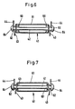
- a conical rotating body 52 is freely rotatably supported on a support pin 53.
- the latter is driven back and forth, namely rotating and in the transverse direction.
- an eccentric 54 is arranged at one end of the trunnion 53.
- An eccentric drive pin 55 is provided with a pinion 56 outside the intermediate container 13. This is driven accordingly by a reciprocating rack 57.
- a common rack is provided for the three movement elements of the exemplary embodiment shown. This accordingly causes the movement members to be moved back and forth across the cigarettes, the rotating bodies 52 being rotatable by the cigarettes.
- the receiving conveyor 22 has a length that is greater than the transverse dimension of the tray 11, in particular namely 1.5 times its width.
- the subsequent intermediate conveyor 24, on the other hand, is dimensioned considerably shorter, namely approximately 0.5 times the width of the tray.
- the length of the conveyor 23 depends on the local conditions of the packaging machine, so that the cigarettes can be fed properly.
- the axes of rotation of the conveyors are, as in particular from Fi g. 2 can be seen, stored in the side walls 18 and 19 of the intermediate container 13.
Landscapes
- Wrapping Of Specific Fragile Articles (AREA)
- Manufacturing Of Cigar And Cigarette Tobacco (AREA)
Applications Claiming Priority (4)
| Application Number | Priority Date | Filing Date | Title |
|---|---|---|---|
| DE19823229092 DE3229092A1 (de) | 1982-08-04 | 1982-08-04 | Vorrichtung zur zufuehrung von zigaretten oder dgl. zu einer verpackungsmaschine |
| DE3229092 | 1982-08-04 | ||
| DE19833304131 DE3304131A1 (de) | 1982-08-04 | 1983-02-08 | Vorrichtung zum transport von zigaretten od. dgl. zu einer verpackungsmaschine |
| DE3304131 | 1983-02-08 |
Related Child Applications (2)
| Application Number | Title | Priority Date | Filing Date |
|---|---|---|---|
| EP85108970.6 Division-Into | 1983-07-21 | ||
| EP85108970A Division EP0177688A3 (fr) | 1983-02-08 | 1983-07-21 | Dispositif pour le transport de cigarettes ou analogues vers une machine d'empaquetage |
Publications (2)
| Publication Number | Publication Date |
|---|---|
| EP0100494A1 true EP0100494A1 (fr) | 1984-02-15 |
| EP0100494B1 EP0100494B1 (fr) | 1988-07-20 |
Family
ID=25803537
Family Applications (1)
| Application Number | Title | Priority Date | Filing Date |
|---|---|---|---|
| EP83107144A Expired EP0100494B1 (fr) | 1982-08-04 | 1983-07-21 | Dispositif d'alimentation en cigarettes ou analogues pour une machine d'empaquetage |
Country Status (5)
| Country | Link |
|---|---|
| US (1) | US4790333A (fr) |
| EP (1) | EP0100494B1 (fr) |
| JP (1) | JPS5948068A (fr) |
| BR (1) | BR8304174A (fr) |
| DE (1) | DE3377396D1 (fr) |
Cited By (2)
| Publication number | Priority date | Publication date | Assignee | Title |
|---|---|---|---|---|
| FR2571704A1 (fr) * | 1984-10-11 | 1986-04-18 | Gd Spa | Dispositif d'alimentation d'articles en forme de barrettes tels que des cigarettes, en direction d'une machine utilisatrice |
| US5406248A (en) * | 1991-06-24 | 1995-04-11 | Ssg-Thomson Microelectronics S.A. | Method and apparatus for managing information transmissions on an electrical distribution circuit |
Families Citing this family (9)
| Publication number | Priority date | Publication date | Assignee | Title |
|---|---|---|---|---|
| GB8826777D0 (en) * | 1988-11-16 | 1988-12-21 | Imp Tobacco Ltd | Article conveying device |
| IT1252438B (it) * | 1991-07-19 | 1995-06-14 | Gd Spa | Dispositivo per l'alimentazione di filtri ad una macchina mettifiltro |
| JP3301449B2 (ja) * | 1992-12-14 | 2002-07-15 | 日本たばこ産業株式会社 | ロッド材のホッパ装置 |
| GB9821665D0 (en) * | 1998-10-05 | 1998-11-25 | Molins Plc | Container handling apparatus |
| DE19901248B4 (de) * | 1999-01-15 | 2012-07-19 | Focke & Co. (Gmbh & Co. Kg) | Verfahren und Vorrichtung zum Fördern von Zigaretten |
| ITBO20010776A1 (it) * | 2001-12-21 | 2003-06-21 | Gd Spa | Dispositivo per il collegamento tra una unita' erogatrice ed una unita' utilizzatrice di prodotti da fumo |
| DE10342903B4 (de) * | 2003-09-17 | 2006-03-09 | Siempelkamp Maschinen- Und Anlagenbau Gmbh & Co. Kg | Streugutbunker mit einer Austragsvorrichtung zum Streuen von Streugut |
| DE102007035399A1 (de) * | 2007-07-26 | 2009-02-05 | Focke & Co.(Gmbh & Co. Kg) | Verfahren und Vorrichtung zum kontrollierten Fördern eines Zigarettenstroms |
| DE102007038839A1 (de) * | 2007-08-16 | 2009-02-19 | Deutsche Post Ag | Transportbehälter mit Fördersystem; Verfahren zum Entladen von Transportbehältern |
Citations (5)
| Publication number | Priority date | Publication date | Assignee | Title |
|---|---|---|---|---|
| GB1126664A (en) * | 1964-12-18 | 1968-09-11 | Horace Alexander Stone | Improvements in or relating to apparatus for feeding cigarettes |
| DE1811884A1 (de) * | 1967-11-30 | 1969-06-19 | Tobacco Res And Dev I Ltd | Behaelter zum Bereithalten loser Erzeugnisse |
| DE2841266A1 (de) * | 1978-09-22 | 1980-04-03 | Hauni Werke Koerber & Co Kg | Steueranordnung fuer einen strom von stabfoermigen gegenstaenden, insbesondere zigaretten oder filterstaeben |
| EP0022943A1 (fr) * | 1979-07-21 | 1981-01-28 | FOCKE & CO. | Dispositif d'alimentation en cigarettes à partir de récipients, pour une machine à empaqueter ou analogue |
| GB1585066A (en) * | 1977-08-18 | 1981-02-25 | Molins Ltd | Apparatus for feeding rod-like articles |
Family Cites Families (9)
| Publication number | Priority date | Publication date | Assignee | Title |
|---|---|---|---|---|
| US3065933A (en) * | 1960-05-20 | 1962-11-27 | Frank Krause Jr A | Helicopter |
| SE323312B (fr) * | 1968-11-27 | 1970-04-27 | Arenco Ab | |
| JPS4834919A (fr) * | 1971-09-02 | 1973-05-23 | ||
| US3976085A (en) * | 1973-04-23 | 1976-08-24 | Liggett & Myers, Incorporated | Automatic cigarette feed machine |
| JPS52151800A (en) * | 1976-06-11 | 1977-12-16 | Hauni Werke Koerber & Co Kg | Apparatus for conveying flow of roddshaped article* particularly cigarette filter rods or similar articles |
| GB1589368A (en) * | 1976-12-16 | 1981-05-13 | Molins Ltd | Conveyor systems forcigarettes and similar rod-like articles |
| JPS5418359A (en) * | 1977-07-08 | 1979-02-10 | Yoshio Adachi | Iron seat support |
| IT1108854B (it) * | 1978-09-14 | 1985-12-16 | Gd Spa | Sistema di alimentazione di elementi allungati particolarmente sigarette ad una macchina impacchettatrice |
| IT1136110B (it) * | 1980-01-25 | 1986-08-27 | Cir Spa Divisione Sasib | Dispositivo perfezionato per la formazione di uno strato compatto di un dato numero di oggetti astiformi in particolare sigarette |
-
1983
- 1983-07-21 EP EP83107144A patent/EP0100494B1/fr not_active Expired
- 1983-07-21 DE DE8383107144T patent/DE3377396D1/de not_active Expired
- 1983-08-01 US US06/519,480 patent/US4790333A/en not_active Expired - Fee Related
- 1983-08-03 BR BR8304174A patent/BR8304174A/pt not_active IP Right Cessation
- 1983-08-04 JP JP58141994A patent/JPS5948068A/ja active Granted
Patent Citations (5)
| Publication number | Priority date | Publication date | Assignee | Title |
|---|---|---|---|---|
| GB1126664A (en) * | 1964-12-18 | 1968-09-11 | Horace Alexander Stone | Improvements in or relating to apparatus for feeding cigarettes |
| DE1811884A1 (de) * | 1967-11-30 | 1969-06-19 | Tobacco Res And Dev I Ltd | Behaelter zum Bereithalten loser Erzeugnisse |
| GB1585066A (en) * | 1977-08-18 | 1981-02-25 | Molins Ltd | Apparatus for feeding rod-like articles |
| DE2841266A1 (de) * | 1978-09-22 | 1980-04-03 | Hauni Werke Koerber & Co Kg | Steueranordnung fuer einen strom von stabfoermigen gegenstaenden, insbesondere zigaretten oder filterstaeben |
| EP0022943A1 (fr) * | 1979-07-21 | 1981-01-28 | FOCKE & CO. | Dispositif d'alimentation en cigarettes à partir de récipients, pour une machine à empaqueter ou analogue |
Cited By (2)
| Publication number | Priority date | Publication date | Assignee | Title |
|---|---|---|---|---|
| FR2571704A1 (fr) * | 1984-10-11 | 1986-04-18 | Gd Spa | Dispositif d'alimentation d'articles en forme de barrettes tels que des cigarettes, en direction d'une machine utilisatrice |
| US5406248A (en) * | 1991-06-24 | 1995-04-11 | Ssg-Thomson Microelectronics S.A. | Method and apparatus for managing information transmissions on an electrical distribution circuit |
Also Published As
| Publication number | Publication date |
|---|---|
| EP0100494B1 (fr) | 1988-07-20 |
| JPS5948068A (ja) | 1984-03-19 |
| US4790333A (en) | 1988-12-13 |
| BR8304174A (pt) | 1984-03-13 |
| JPH0553471B2 (fr) | 1993-08-10 |
| DE3377396D1 (en) | 1988-08-25 |
Similar Documents
| Publication | Publication Date | Title |
|---|---|---|
| EP1020126B1 (fr) | Dispositif pour transporter des cigarettes | |
| DE60118772T2 (de) | Zufuhrsystem für vorformen insbesondere geeignet für eine behälter blasmaschine | |
| DE1957002C3 (de) | Fördereinrichtung zum Fördern von Zigaretten | |
| DE3527741C2 (fr) | ||
| DE60009470T2 (de) | Methoden und vorrichtung zur förderung von paketen unter minimaler blockierung | |
| DE3713509A1 (de) | Foerderanlage fuer stabfoermige gegenstaende | |
| DD295326A5 (de) | Verfahren und vorrichtung zum sukzessiven zufuehren flacher produkte | |
| EP0100494B1 (fr) | Dispositif d'alimentation en cigarettes ou analogues pour une machine d'empaquetage | |
| DE547874C (de) | Rollenfoerderer | |
| EP0300958B1 (fr) | Dispositif de transport pour des produits en position verticale en particulier des biscuits | |
| DE19959131A1 (de) | Ladevorrichtung für einen Bogenbehälter und Verfahren | |
| DE69108637T2 (de) | Automatische Maschinen zur vertikalen Positionierung von Behältern. | |
| DD140132A5 (de) | Vorrichtung zum beschicken einer packmaschine mit suesswaren | |
| EP1234790B1 (fr) | Dispositif pour transférer des objets plats alimentés seriellement à une section de déchargement | |
| DE3119016C2 (fr) | ||
| EP0649597A1 (fr) | Installation pour fabriquer des tablettes de chocolat ou des produits similaires | |
| DE69921316T2 (de) | Automatische ausrichtungs- und ausgabevorrichtung für werkstücke | |
| EP0177688A2 (fr) | Dispositif pour le transport de cigarettes ou analogues vers une machine d'empaquetage | |
| DE4342084C2 (de) | Vorrrichtung zum Ausrichten von Gegenständen | |
| DE69104589T2 (de) | Dynamische Speichervorrichtung für Behälter in einer pneumatisch betriebenen Transferstrasse. | |
| DE2716823C2 (fr) | ||
| EP3453651A1 (fr) | Unité de transport et d'alimentation pour préformes | |
| DE2213990A1 (de) | Sammelfoerdergeraet | |
| CH646111A5 (de) | Vorrichtung zum umkippen aufeinanderfolgender gegenstaende. | |
| EP0703148B2 (fr) | Procédé et dispositif pour la manipulation d'objets cylindriques, spécialement des rouleaux de biscuits |
Legal Events
| Date | Code | Title | Description |
|---|---|---|---|
| PUAI | Public reference made under article 153(3) epc to a published international application that has entered the european phase |
Free format text: ORIGINAL CODE: 0009012 |
|
| AK | Designated contracting states |
Designated state(s): DE FR GB IT SE |
|
| 17P | Request for examination filed |
Effective date: 19840707 |
|
| RAP1 | Party data changed (applicant data changed or rights of an application transferred) |
Owner name: FOCKE & CO. (GMBH & CO.) |
|
| ITF | It: translation for a ep patent filed | ||
| GRAA | (expected) grant |
Free format text: ORIGINAL CODE: 0009210 |
|
| AK | Designated contracting states |
Kind code of ref document: B1 Designated state(s): DE FR GB IT SE |
|
| GBT | Gb: translation of ep patent filed (gb section 77(6)(a)/1977) | ||
| REF | Corresponds to: |
Ref document number: 3377396 Country of ref document: DE Date of ref document: 19880825 |
|
| ET | Fr: translation filed | ||
| PLBE | No opposition filed within time limit |
Free format text: ORIGINAL CODE: 0009261 |
|
| STAA | Information on the status of an ep patent application or granted ep patent |
Free format text: STATUS: NO OPPOSITION FILED WITHIN TIME LIMIT |
|
| 26N | No opposition filed | ||
| ITTA | It: last paid annual fee | ||
| EAL | Se: european patent in force in sweden |
Ref document number: 83107144.4 |
|
| PGFP | Annual fee paid to national office [announced via postgrant information from national office to epo] |
Ref country code: SE Payment date: 19970716 Year of fee payment: 15 |
|
| PG25 | Lapsed in a contracting state [announced via postgrant information from national office to epo] |
Ref country code: SE Free format text: LAPSE BECAUSE OF NON-PAYMENT OF DUE FEES Effective date: 19980722 |
|
| EUG | Se: european patent has lapsed |
Ref document number: 83107144.4 |
|
| PGFP | Annual fee paid to national office [announced via postgrant information from national office to epo] |
Ref country code: GB Payment date: 20000719 Year of fee payment: 18 |
|
| PGFP | Annual fee paid to national office [announced via postgrant information from national office to epo] |
Ref country code: FR Payment date: 20000725 Year of fee payment: 18 |
|
| PGFP | Annual fee paid to national office [announced via postgrant information from national office to epo] |
Ref country code: DE Payment date: 20010719 Year of fee payment: 19 |
|
| PG25 | Lapsed in a contracting state [announced via postgrant information from national office to epo] |
Ref country code: GB Free format text: LAPSE BECAUSE OF NON-PAYMENT OF DUE FEES Effective date: 20010721 |
|
| GBPC | Gb: european patent ceased through non-payment of renewal fee |
Effective date: 20010721 |
|
| PG25 | Lapsed in a contracting state [announced via postgrant information from national office to epo] |
Ref country code: FR Free format text: LAPSE BECAUSE OF NON-PAYMENT OF DUE FEES Effective date: 20020329 |
|
| REG | Reference to a national code |
Ref country code: FR Ref legal event code: ST |
|
| PG25 | Lapsed in a contracting state [announced via postgrant information from national office to epo] |
Ref country code: DE Free format text: LAPSE BECAUSE OF NON-PAYMENT OF DUE FEES Effective date: 20030201 |