EP0100556A2 - Séparateur magnétique - Google Patents
Séparateur magnétique Download PDFInfo
- Publication number
- EP0100556A2 EP0100556A2 EP83107649A EP83107649A EP0100556A2 EP 0100556 A2 EP0100556 A2 EP 0100556A2 EP 83107649 A EP83107649 A EP 83107649A EP 83107649 A EP83107649 A EP 83107649A EP 0100556 A2 EP0100556 A2 EP 0100556A2
- Authority
- EP
- European Patent Office
- Prior art keywords
- magnetic
- roller
- plates
- magnetic separator
- rollers
- Prior art date
- Legal status (The legal status is an assumption and is not a legal conclusion. Google has not performed a legal analysis and makes no representation as to the accuracy of the status listed.)
- Granted
Links
- 239000006148 magnetic separator Substances 0.000 title claims abstract description 14
- 230000005291 magnetic effect Effects 0.000 claims abstract description 36
- 239000000428 dust Substances 0.000 claims abstract description 20
- 230000005294 ferromagnetic effect Effects 0.000 claims abstract description 10
- 239000006249 magnetic particle Substances 0.000 claims abstract description 6
- 230000005284 excitation Effects 0.000 claims abstract description 4
- 239000000463 material Substances 0.000 abstract description 2
- 238000004140 cleaning Methods 0.000 abstract 1
- 150000001875 compounds Chemical class 0.000 abstract 1
- 238000010276 construction Methods 0.000 abstract 1
- 238000005516 engineering process Methods 0.000 abstract 1
- UQSXHKLRYXJYBZ-UHFFFAOYSA-N iron oxide Inorganic materials [Fe]=O UQSXHKLRYXJYBZ-UHFFFAOYSA-N 0.000 abstract 1
- 235000013980 iron oxide Nutrition 0.000 abstract 1
- VBMVTYDPPZVILR-UHFFFAOYSA-N iron(2+);oxygen(2-) Chemical class [O-2].[Fe+2] VBMVTYDPPZVILR-UHFFFAOYSA-N 0.000 abstract 1
- 238000005272 metallurgy Methods 0.000 abstract 1
- 238000011084 recovery Methods 0.000 abstract 1
- 239000002893 slag Substances 0.000 abstract 1
- 239000002245 particle Substances 0.000 description 3
- 230000000694 effects Effects 0.000 description 2
- 238000000926 separation method Methods 0.000 description 2
- 239000012141 concentrate Substances 0.000 description 1
- 230000008021 deposition Effects 0.000 description 1
- 230000006698 induction Effects 0.000 description 1
- 238000012423 maintenance Methods 0.000 description 1
- 239000000126 substance Substances 0.000 description 1
Images


Classifications
-
- B—PERFORMING OPERATIONS; TRANSPORTING
- B03—SEPARATION OF SOLID MATERIALS USING LIQUIDS OR USING PNEUMATIC TABLES OR JIGS; MAGNETIC OR ELECTROSTATIC SEPARATION OF SOLID MATERIALS FROM SOLID MATERIALS OR FLUIDS; SEPARATION BY HIGH-VOLTAGE ELECTRIC FIELDS
- B03C—MAGNETIC OR ELECTROSTATIC SEPARATION OF SOLID MATERIALS FROM SOLID MATERIALS OR FLUIDS; SEPARATION BY HIGH-VOLTAGE ELECTRIC FIELDS
- B03C1/00—Magnetic separation
- B03C1/02—Magnetic separation acting directly on the substance being separated
- B03C1/10—Magnetic separation acting directly on the substance being separated with cylindrical material carriers
- B03C1/14—Magnetic separation acting directly on the substance being separated with cylindrical material carriers with non-movable magnets
Definitions
- the invention relates to a magnetic separator for separating magnetic particles, in particular from volatile dust.
- a magnetic separator is known from PL-A-87 216, in which the poles form a working air slot in the form of a trapezoid.
- a conveyor belt which carries the magnetic dust deposited thereon out of the area of the magnetic field, is slidably arranged in this slot at the location of the greatest induction of the magnetic field. The arrangement of the movable belt in the area of the flowing dust lowers the dust-tightness and the functionality of the device.
- a magnetic separator is known from PL-A-80 412, the ferromagnetic rotor of which has ferromagnetic teeth on its surface, which are distributed on a helical line.
- the material to be cleaned is placed on the rotary wheel.
- the ferromagnetic particles contained in the substance accumulate in the air slot between the teeth of the impeller and the poles of the magnets, i.e. where the magnetic field strength is greatest.
- these points move towards one end of the gyroscope and thus the ferromagnetic particles also move.
- the magnetic separator according to the invention comprising a ferromagnetic roller, on the surface of which teeth are arranged along a helix, and which is arranged between magnetic poles, is characterized in that a non-magnetic protection is placed on the roller, which is connected to the plates that hold the magnetic poles form, which forms working slots.
- the roller or the cylinder can have additional recesses which cut through the helix of the teeth.
- the arrangement between the plates of at least two cylinders one above the other increases the dust separation effect.
- the non-magnetic protection can be profiled into a shape that corresponds to the radii of the cylinders.
- Projections with a triangular cross section are preferably arranged in the dust flow zone, one of the sides of the triangle abutting the plate surface and the height of the projection being smaller than the width of the working slot. These projections produce an inhomogeneous magnetic field in the entire area of the work area.
- the separator is characterized in that the plates which form the magnetic poles, together with the cylinders and working slots, are arranged symmetrically with respect to the excitation coil.
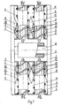
- rollers of the cutter are preferably arranged in at least two vertical rows separated from one another by a working slot, magnetic inserts being arranged in the working slot, which form the triangular dust flow zones.
- Such a roller arrangement makes it possible to increase the throughput of the cutter with the same plate thickness.
- a fundamental advantage of the application of the invention is the maintenance of a high level of dust tightness and functionality by removing the movable elements from the area into which the dust flows.
- high throughput and separation efficiency are ensured by generating an inhomogeneous magnetic field in the entire space of the working slots with the same current consumption.
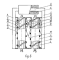
- the dust to be separated is fed through an inlet 7 to the flow zones, which are separated by strips attached to the plates 1. It is divided into two parts in the working slots 4 under the action of the magnetic field, the non-magnetic dust falling to an outlet 8 and the magnetic dust being deposited on the non-magnetic protection 3 at the level of the axes of the rollers 2. By rotating the rollers 2, the magnetic dust is transported along the axes thereof to the end of the slots 4, where it falls into the outlet of the ferromagnetic concentrate.
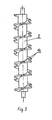
- a roller is shown with additional recesses 14 which cut through the helix of the teeth.
- inserts or projections are attached to the plates, which protrude from the working slots 4 and the dust flow zones 10.
- the plates 1, which play the role of the magnetic poles, together with the rollers 2, working slots 4 and 11 and magnetic inserts 9, 12 are arranged symmetrically with respect to the excitation coil 5.
Landscapes
- Separating Particles In Gases By Inertia (AREA)
- Cyclones (AREA)
- Nonmetal Cutting Devices (AREA)
Applications Claiming Priority (4)
| Application Number | Priority Date | Filing Date | Title |
|---|---|---|---|
| PL23777682A PL134911B1 (en) | 1982-08-03 | 1982-08-03 | Magnetic separator |
| PL237776 | 1982-08-03 | ||
| PL242061 | 1983-05-19 | ||
| PL24206183A PL137774B3 (en) | 1983-05-19 | 1983-05-19 | Magnetic separator |
Publications (3)
| Publication Number | Publication Date |
|---|---|
| EP0100556A2 true EP0100556A2 (fr) | 1984-02-15 |
| EP0100556A3 EP0100556A3 (en) | 1985-01-16 |
| EP0100556B1 EP0100556B1 (fr) | 1986-11-20 |
Family
ID=26652971
Family Applications (1)
| Application Number | Title | Priority Date | Filing Date |
|---|---|---|---|
| EP19830107649 Expired EP0100556B1 (fr) | 1982-08-03 | 1983-08-03 | Séparateur magnétique |
Country Status (4)
| Country | Link |
|---|---|
| EP (1) | EP0100556B1 (fr) |
| CS (1) | CS235336B2 (fr) |
| DD (1) | DD209979A5 (fr) |
| DE (1) | DE3367740D1 (fr) |
Cited By (1)
| Publication number | Priority date | Publication date | Assignee | Title |
|---|---|---|---|---|
| EP0149499A3 (en) * | 1984-01-14 | 1985-08-14 | Akzo N.V. | Novel delta4- and delta5- androstene derivatives, processes for their preparation and pharmaceutical compositions containing these derivatives |
Family Cites Families (2)
| Publication number | Priority date | Publication date | Assignee | Title |
|---|---|---|---|---|
| US1948419A (en) * | 1929-09-02 | 1934-02-20 | Granigg Bartel | Method of and means for the magnetic separation of materials |
| US2913113A (en) * | 1957-08-30 | 1959-11-17 | Los Angeles By Products Co | Method and apparatus for salvaging metal articles |
-
1983
- 1983-08-01 DD DD25360783A patent/DD209979A5/de unknown
- 1983-08-02 CS CS573983A patent/CS235336B2/cs unknown
- 1983-08-03 DE DE8383107649T patent/DE3367740D1/de not_active Expired
- 1983-08-03 EP EP19830107649 patent/EP0100556B1/fr not_active Expired
Cited By (1)
| Publication number | Priority date | Publication date | Assignee | Title |
|---|---|---|---|---|
| EP0149499A3 (en) * | 1984-01-14 | 1985-08-14 | Akzo N.V. | Novel delta4- and delta5- androstene derivatives, processes for their preparation and pharmaceutical compositions containing these derivatives |
Also Published As
| Publication number | Publication date |
|---|---|
| EP0100556A3 (en) | 1985-01-16 |
| EP0100556B1 (fr) | 1986-11-20 |
| CS235336B2 (en) | 1985-05-15 |
| DE3367740D1 (en) | 1987-01-08 |
| DD209979A5 (de) | 1984-05-30 |
Similar Documents
| Publication | Publication Date | Title |
|---|---|---|
| DE69211276T2 (de) | Verfahren und Schleifvorrichtung | |
| DE2551030C3 (de) | Abwasserreinigungsvorrichtung mit einer um eine liegende Welle rotierenden Vorrichtung mit Magneten | |
| DE202012013256U1 (de) | Vorrichtung zur Trennung nichtmagnetischer Bestandteile aus einem Gemenge von Metallschrott | |
| DE8002678U1 (de) | Metallsortiervorrichtung | |
| DE2612834A1 (de) | Magnetscheider | |
| EP0100556B1 (fr) | Séparateur magnétique | |
| DE2555798A1 (de) | Verfahren und vorrichtung zum trennen von magnetischen teilchen | |
| EP0006885B1 (fr) | Séparateur magnétique à bandes transporteuses croisées | |
| DE2501858C2 (de) | Vorrichtung zum Abscheiden magnetisierbarer Teilchen, die in einer Flüssigkeit suspendiert sind | |
| DE2749661C2 (de) | Magnetscheider | |
| DE827181C (de) | Magnetscheider | |
| DE19629110C1 (de) | Verfahren und Vorrichtung zum Trennen von feinteiligen Stoffgemischen mittels eines magnetischen Feldes | |
| DE732133C (de) | Verfahren und Vorrichtung zur magnetischen Aufbereitung von Mineralien u. dgl. im Feldspalt zwischen zwei Magnetpolen und einer umlaufenden Walze | |
| DE870532C (de) | Einrichtung zum Abscheiden magnetisierbarer Stoffe aus pulverfoermigem Gut | |
| DE2532493A1 (de) | Verfahren und vorrichtung zur nassmagnetischen aufbereitung von feinkoernigem feststoff | |
| DE4132383C1 (en) | Arrangement for sepg. weakly magnetic impurities from e.g. cooling liquids - includes transport surface with associated magnet device, and nozzle above surface to supply coolant liq. | |
| DE3423866C2 (de) | Vorrichtung zum Abtrennen nicht magnetisierbarer elektrisch leitfähiger Metallteile aus einem Feststoffgemisch | |
| DE19726745B4 (de) | Verfahren zum Abscheiden von Teilchen | |
| DE288299C (fr) | ||
| DE3333344C2 (fr) | ||
| DE916821C (de) | Permanentmagnetischer Magnetrost-Scheider | |
| DE3324926A1 (de) | Siebvorrichtung | |
| DE3590172T (de) | Desintegrator | |
| DE521020C (de) | Verfahren und Vorrichtung zur elektromagnetischen Trennung von mineralischem Gut | |
| DE680514C (de) | Sandaufbereitungsmaschine |
Legal Events
| Date | Code | Title | Description |
|---|---|---|---|
| PUAI | Public reference made under article 153(3) epc to a published international application that has entered the european phase |
Free format text: ORIGINAL CODE: 0009012 |
|
| AK | Designated contracting states |
Designated state(s): DE FR GB |
|
| PUAL | Search report despatched |
Free format text: ORIGINAL CODE: 0009013 |
|
| AK | Designated contracting states |
Designated state(s): DE FR GB |
|
| 17P | Request for examination filed |
Effective date: 19841227 |
|
| GRAA | (expected) grant |
Free format text: ORIGINAL CODE: 0009210 |
|
| AK | Designated contracting states |
Kind code of ref document: B1 Designated state(s): DE FR GB |
|
| REF | Corresponds to: |
Ref document number: 3367740 Country of ref document: DE Date of ref document: 19870108 |
|
| ET | Fr: translation filed | ||
| PLBE | No opposition filed within time limit |
Free format text: ORIGINAL CODE: 0009261 |
|
| STAA | Information on the status of an ep patent application or granted ep patent |
Free format text: STATUS: NO OPPOSITION FILED WITHIN TIME LIMIT |
|
| 26N | No opposition filed | ||
| PG25 | Lapsed in a contracting state [announced via postgrant information from national office to epo] |
Ref country code: GB Free format text: LAPSE BECAUSE OF NON-PAYMENT OF DUE FEES Effective date: 19880803 |
|
| PG25 | Lapsed in a contracting state [announced via postgrant information from national office to epo] |
Ref country code: FR Free format text: LAPSE BECAUSE OF NON-PAYMENT OF DUE FEES Effective date: 19890428 |
|
| PG25 | Lapsed in a contracting state [announced via postgrant information from national office to epo] |
Ref country code: DE Effective date: 19890503 |
|
| GBPC | Gb: european patent ceased through non-payment of renewal fee | ||
| REG | Reference to a national code |
Ref country code: FR Ref legal event code: ST |