EP0100917B1 - Circuit de refroidissement pour moteurs à combustion interne - Google Patents
Circuit de refroidissement pour moteurs à combustion interne Download PDFInfo
- Publication number
- EP0100917B1 EP0100917B1 EP83106971A EP83106971A EP0100917B1 EP 0100917 B1 EP0100917 B1 EP 0100917B1 EP 83106971 A EP83106971 A EP 83106971A EP 83106971 A EP83106971 A EP 83106971A EP 0100917 B1 EP0100917 B1 EP 0100917B1
- Authority
- EP
- European Patent Office
- Prior art keywords
- pressure
- over
- coolant
- valve
- cooling circuit
- Prior art date
- Legal status (The legal status is an assumption and is not a legal conclusion. Google has not performed a legal analysis and makes no representation as to the accuracy of the status listed.)
- Expired
Links
- 238000001816 cooling Methods 0.000 title claims description 66
- 238000002485 combustion reaction Methods 0.000 title claims description 7
- 239000002826 coolant Substances 0.000 claims description 79
- 239000000945 filler Substances 0.000 claims description 44
- 238000012384 transportation and delivery Methods 0.000 claims description 5
- 238000009835 boiling Methods 0.000 claims description 4
- 230000000694 effects Effects 0.000 claims description 4
- 238000000926 separation method Methods 0.000 claims description 3
- 230000001105 regulatory effect Effects 0.000 claims 1
- XLYOFNOQVPJJNP-UHFFFAOYSA-N water Substances O XLYOFNOQVPJJNP-UHFFFAOYSA-N 0.000 description 17
- 238000002156 mixing Methods 0.000 description 11
- 238000009423 ventilation Methods 0.000 description 9
- 238000013461 design Methods 0.000 description 4
- 238000000034 method Methods 0.000 description 4
- 238000010438 heat treatment Methods 0.000 description 3
- 238000011144 upstream manufacturing Methods 0.000 description 3
- 238000013022 venting Methods 0.000 description 3
- 238000010276 construction Methods 0.000 description 2
- 238000001704 evaporation Methods 0.000 description 2
- 238000012423 maintenance Methods 0.000 description 2
- 238000003303 reheating Methods 0.000 description 2
- 239000008400 supply water Substances 0.000 description 2
- 230000032683 aging Effects 0.000 description 1
- 230000015572 biosynthetic process Effects 0.000 description 1
- 238000011161 development Methods 0.000 description 1
- 230000018109 developmental process Effects 0.000 description 1
- 230000008020 evaporation Effects 0.000 description 1
- 230000002349 favourable effect Effects 0.000 description 1
- 230000017525 heat dissipation Effects 0.000 description 1
- 238000010137 moulding (plastic) Methods 0.000 description 1
- 239000002245 particle Substances 0.000 description 1
- 238000012552 review Methods 0.000 description 1
- 238000007789 sealing Methods 0.000 description 1
- 230000003068 static effect Effects 0.000 description 1
- 238000012549 training Methods 0.000 description 1
- 238000012546 transfer Methods 0.000 description 1
Images

Classifications
-
- F—MECHANICAL ENGINEERING; LIGHTING; HEATING; WEAPONS; BLASTING
- F01—MACHINES OR ENGINES IN GENERAL; ENGINE PLANTS IN GENERAL; STEAM ENGINES
- F01P—COOLING OF MACHINES OR ENGINES IN GENERAL; COOLING OF INTERNAL-COMBUSTION ENGINES
- F01P11/00—Component parts, details, or accessories not provided for in, or of interest apart from, groups F01P1/00 - F01P9/00
- F01P11/02—Liquid-coolant filling, overflow, venting, or draining devices
- F01P11/0204—Filling
- F01P11/0209—Closure caps
- F01P11/0247—Safety; Locking against opening
-
- F—MECHANICAL ENGINEERING; LIGHTING; HEATING; WEAPONS; BLASTING
- F01—MACHINES OR ENGINES IN GENERAL; ENGINE PLANTS IN GENERAL; STEAM ENGINES
- F01P—COOLING OF MACHINES OR ENGINES IN GENERAL; COOLING OF INTERNAL-COMBUSTION ENGINES
- F01P11/00—Component parts, details, or accessories not provided for in, or of interest apart from, groups F01P1/00 - F01P9/00
- F01P11/02—Liquid-coolant filling, overflow, venting, or draining devices
- F01P11/0204—Filling
- F01P11/0209—Closure caps
- F01P11/0238—Closure caps with overpressure valves or vent valves
-
- F—MECHANICAL ENGINEERING; LIGHTING; HEATING; WEAPONS; BLASTING
- F01—MACHINES OR ENGINES IN GENERAL; ENGINE PLANTS IN GENERAL; STEAM ENGINES
- F01P—COOLING OF MACHINES OR ENGINES IN GENERAL; COOLING OF INTERNAL-COMBUSTION ENGINES
- F01P11/00—Component parts, details, or accessories not provided for in, or of interest apart from, groups F01P1/00 - F01P9/00
- F01P11/02—Liquid-coolant filling, overflow, venting, or draining devices
- F01P11/028—Deaeration devices
-
- F—MECHANICAL ENGINEERING; LIGHTING; HEATING; WEAPONS; BLASTING
- F01—MACHINES OR ENGINES IN GENERAL; ENGINE PLANTS IN GENERAL; STEAM ENGINES
- F01P—COOLING OF MACHINES OR ENGINES IN GENERAL; COOLING OF INTERNAL-COMBUSTION ENGINES
- F01P11/00—Component parts, details, or accessories not provided for in, or of interest apart from, groups F01P1/00 - F01P9/00
- F01P11/02—Liquid-coolant filling, overflow, venting, or draining devices
- F01P11/0204—Filling
- F01P11/0209—Closure caps
- F01P11/0247—Safety; Locking against opening
- F01P2011/0266—Safety; Locking against opening activated by pressure
Definitions
- the invention relates to a cooling circuit according to the design of claim 1.
- cooling circuits of this type it is known to fill the filler neck and thus also the pressure and vacuum valves contained in the filler neck cover either in the flow area of the cooler between the cooling jacket of the internal combustion engine and the cooler - Arrange the flow water box or in the return area of the cooler between the cooler return water box and the suction side of the coolant pump (Technical Review No. 46, 1971, page 9).
- the pressure relief valve is located at a point in the cooling circuit at which its function accordingly occurs and is at least approximately the highest pressure during operation of the machine and is limited. At this point, however, the vacuum valve cannot fully serve its purpose, because the lowest pressure in the cooling circuit occurs on the suction side of the coolant pump during operation and therefore cannot be used by the vacuum valve.
- the pressure relief valve is due to the aforementioned relationships at a point where it cannot perform its function, while the vacuum valve is fully effective.
- the object of the invention is to develop the cooling circuit of the known type of claim 1 so that the favorable summary of the pressure and vacuum valves in the filler cap can be maintained and still both valves on the one hand at the highest overpressure occurring in the flow area and on the other hand at the lowest negative pressure that occurs in the return area has a functional effect.
- the invention provides the features according to the characterizing part of patent claim 1.
- the separate control of the pressure and vacuum valves is achieved with the low construction costs of a further separate control room in the filler neck cover and a further line connection.
- Claims 2 to 16 contain preferred refinements and developments of the invention.
- the features of claims 2 and 3 contain the additional use and design of the line connection acting as an overpressure control line to the overpressure valve as an outflow line for the coolant to be discharged from the overpressure valve or as a continuously effective throttled vent line with a throttle connected in parallel with the overpressure valve. that secures the supply of the pre-opening pressure to the pressure relief valve without pressure drop.
- a ventilation line that is often present in known cooling systems and is connected to the flow area.
- Claims 4 and 5 contain preferred configurations of the invention for the arrangement of the throttle for the ventilation line.
- the features of claim 6 provide to combine further control elements for the cooling circuit in the filler neck and filler neck cover.
- the features of claim 7 include the arrangement and dimensioning of a further pressure relief valve, which ensures that at low engine speeds and therefore low pump delivery capacity, a lower overpressure is built up in the entire cooling circuit than is determined by the pressure relief valve controlled by the flow area according to claim 1. On the one hand, this reduces the pressure load on the cooling circuit during part-load operation of the machine and achieves the venting effect by opening the additional pressure relief valve by pushing out any air that may have accumulated at a lower pressure without, on the other hand, impairing the advantageous limitation of the coolant pressure by the pressure relief and vacuum relief valves.
- claim 8 contain a structurally advantageous summary of the two pressure relief valve functions according to the training according to claims 1 and 7 in a double valve.
- the features of claim 9 contain a pressure control valve which is remotely controlled from the supply pressure and which controls the coolant from the pressure region of the suction side of the coolant pump. which also promotes ventilation of the cooling system.
- a single pressure relief valve is actuated by both pressure areas, namely the flow area and the return area, thus combining the functions of two pressure relief valves in it.
- the features of claim 11 contain a coordination of the two overpressure opening values for the overpressure valve according to claim 10.
- the features of claim 12 include the structural design of a cooling circuit with a pressure relief valve according to claims 10 or 11 in connection with a particularly effective ventilation device.
- the features of claims 13 and 14 further develop the objects according to claims 10 to 12 such that according to claim 15, in connection with a bypass expansion tank with expansion air space through the pressure relief valve and the vacuum valve, only portions of the air space content - And are derived or that the ventilation bypass flow is introduced as a ventilation vortex into the expansion tank in order to effectively separate air residues distributed in the cooling circuit from the coolant.
- Claims 16 and 17 contain features for the dimensionally reliable dimensioning of the overpressure opening value for an overpressure valve controlled by the flow area, which at the same time excludes higher overpressure values which occur with known return area control of an overpressure valve due to an aging-related increase in the cooler flow resistance.
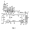
- An internal combustion engine 1 contains a cooling jacket 2, indicated by an arrow, into which the coolant is conveyed under pressure by means of a coolant pump 3.
- a flow line 5 is connected with a free passage to a cooler 6.
- the flow 5 opens into a cooler flow water tank 7.
- a short circuit 8 branches off from the flow 5 and opens into a mixing thermostat 9, this opening being controlled by a short circuit valve 10 of the mixing thermostat 9.
- From a cooler return water box 11, a line forming the return 12 from the cooler 6 likewise leads into the mixing thermostat 9, which contains a cooler valve 13 for controlling the mouth of the return 12.
- a suction line 15 opens from a mixing chamber 14 of the mixing thermostat 9 and opens into the suction side 16 of the coolant pump 3.
- a pressure relief valve 17 is connected to the cooler flow water tank 7 by means of an outflow line 18 in order to be connected to an expansion tank 19 open to the atmosphere by means of a suction line 20.
- the expansion tank 19 is equipped with a slotted sealing disk 19 'in its filling opening.
- the pressure relief valve 17 can alternatively be connected to the flow 5 or to the cooling jacket 2 of the machine.
- the expansion tank 19 is connected to the suction side 16 of the coolant pump 3 via the suction line 20 and a vacuum valve 21, which preferably acts as a non-return valve.
- the suction line 20 opens out from the interior of the expansion tank 19 near the floor.
- One or more relatively large-area fine screens 22 and 23 in the cooler 6 and in the expansion tank 19 prevent the valves from becoming leaky due to dirt particles entrained by the coolant.
- the pressure relief valve 17 and the vacuum relief valve 21 are combined in a filler neck 21 'to form a structural unit.
- a further pressure relief valve 24 is arranged in the filler neck 21 ′ and is effective via the suction line 20 directly on the suction side 16 of the coolant pump 3 and thus on its suction pressure.
- the outflow line 18 opens into the interior of the filler neck 21 'as a vent line by means of a throttle 26 for reducing the pressure difference between its connections on the one hand on the flow water tank 7 and on the other hand via the suction line 20 on the suction side 16 of the coolant pump 3.
- a level float switch 21 " is installed, which controls a display circuit when air accumulates in the filler neck 21 ', irrespective of whether the reservoir 19 still contains an optically recognizable reserve quantity or not.
- the pressure relief valves 17 and 24 are actuated by their respective control chambers 17 'and 2T in the opposite opening directions and in the likewise opposite closing directions by a single valve spring 24'.
- Different overpressure opening values of, for example, 2 or 1.5 bar are achieved by an inversely proportional dimensioning of the opening cross sections of the two valves.
- the respective connection of the outflow line 18 and the expansion tank 19 via the suction line 20 on the cover 27 takes place via sealed ring grooves 30 and 31, which are arranged between the filler neck 21 'and cover 27.
- the first increase in speed immediately leads to the build-up of a delivery head of the coolant pump 3, which on the one hand causes the pump suction pressure to drop below the environment in the entire cooling circuit before the start pressure and on the other hand builds up an excess pressure in the coolant pump 3 downstream cooler sections, cooling jacket 2, flow 5, short circuit 8, cooler 6 and return 12. While this overpressure does not reach the opening pressure value of the overpressure valve 17, the vacuum valve 21, which responds to the slightest pressure difference and the suction line 20 from the expansion tank 19, draws coolant into the cooling circuit until the ambient pressure is reached on the suction side 16 of the coolant pump 3. During this process, the overpressure in the parts of the cooling circuit downstream of the coolant pump 3 simultaneously increases further.
- the elastic hose lines and any residual air inclusions in this area allow an increase in the volume of coolant contained therein.
- the Opening value of the pressure relief valve 17 of, for example, 2 bar or of the pressure relief valve 24 of, for example, 1.5 bar was reached more or less early before or after opening the cooler valve 13 of the mixing thermostat 9.
- the engine speed is decisive because the low head of the coolant pump 3 that occurs at low to medium speeds first enables the pressure relief valve 24 to respond, which responds with an overpressure opening value that is just that pressure difference lower than the overpressure opening value of the pressure relief valve 17 that builds up between standstill or idling speed and maximum speed of the machine at the connection point of the pressure relief valve 17. At low engine speeds, the pressure relief valve 24 responds, which is connected to the suction side 16 of the coolant pump 3 via the control chamber 27 'and the suction line 20. Only in the range of the maximum speed of the machine is the overpressure opening value of the overpressure valve 17 connected via the control chamber 17 ′ and the outflow line 18 to the cooler flow water tank 7.
- an internal pressure from the ambient pressure up to the opening pressure value of the pressure relief valve 17 and during operation of the machine 1 in the cooling jacket 2 and in the feed line 5 as well as in the short circuit 8 can therefore result in an overpressure depending on the flow resistance of the cooling circuit.
- a pressure overload of the cooling circuit components does not exist due to this relatively low, exclusively statically effective overpressure.
- the higher overpressure determined by the pressure relief valve 17 is limited to the operation of the machine 1 at relatively high engine speeds, at which the pressure difference between the suction side 16 of the coolant pump 3 and the connection point of the pressure relief valve 17 is greater than the difference in the pressure opening values between the pressure relief valves 17 on the one hand and 24 on the other. This higher overpressure is thus limited to a relatively small proportion of the operating time of the machine, especially when driving vehicles.
- the durability of the cooling circuit components, in particular the cooler and the hose lines, is thereby favored.
- the cooling circuit When the machine starts operating after the cooling circuit has been filled with coolant, the cooling circuit also begins to be vented automatically from residual air components which remain at various points during filling ben or get into the cooling circuit during operation, for example through the seals of the coolant pump 3, which are briefly loaded with negative pressure during the cold start. These residual air fractions are flushed with the flow of the coolant from the machine 1 through the free continuous flow 5 into the cooler flow water tank 7, in which only the one determined by the throttle 26 relative to the thermostat 9 during the heating of the machine with the cooler valve 13 closed low ventilation flow.
- Venting also occurs when the overpressure opening value of approximately 2.0 bar of the overpressure valve 17 is reached in the cooler flow water tank. However, no upstream residual air fractions are removed, but only residual air fractions directly contained or dissolved in the emerging coolant are discharged into the expansion tank 19 and thus into the atmosphere.
- a further venting and pushing out of coolant with residual air from the filler neck 21 'into the expansion tank 19 through the pressure relief valve 24 also occurs whenever, after a warm-up operating time with a high engine speed of approximately 5,000 to 6,000 / min and a high pressure difference of about 1 bar between the cooler flow water tank 7 and the suction side 16 of the coolant pump 3, the engine speed drops considerably, in particular to the idling speed.
- the overpressure opening value of about 2 bar of the overpressure valve 17 is namely at least approximately reached at first and, in contrast, the overpressure opening value of about 1.5 bar of the further overpressure valve 24 is substantially undercut.
- the overpressure values then largely adjust to one another, so that the overpressure in the filler neck 21 ′ increases approximately to the overpressure opening value of the overpressure valve 24 there.
- the overpressure opening value of the pressure relief valve 24 is exceeded by the corresponding thermal expansion of the coolant.
- the residual air which may have been upstream in the filler neck 21 ' is discharged into the expansion tank 19 together with a portion of coolant.
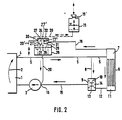
- the configuration of the cooling circuit according to FIG. 2 largely corresponds to that according to FIG. 1 both in terms of structure and function. Only the filler neck 21 'is alternatively combined with a secondary flow expansion tank 28 with air space 29 or designed as a filler neck 21' without air space 29 (shown in dashed lines).
- the evaporation line 20 'opening into the atmosphere should therefore only be provided in combination with an air space 29, while the expansion tank 19 and the suction line 20 can interact both with a secondary flow expansion tank 28 without air space 29 and with a filler neck 21' without air space.
- a single pressure relief valve 24 and a piston 32 acting as a servomotor on this are arranged in the cover 27 of the filler neck 21 '.
- the piston 32 is acted upon by the excess pressure in the cooler flow water tank 7 by the outflow line 18, which is only effective as a control and ventilation line.
- a push rod 32 ' transmits the control movement of the piston 32 to the pressure relief valve 24.
- the effective cross sections of the piston 32 and the pressure relief valve 24 are matched to the valve spring 24' of the pressure relief valve 24 in such a way that the pressure relief valve is at about 2 bar pressure on the suction side 16, for example the coolant pump 3 is opened directly by this overpressure, while it is actuated by the predominant compressive force of the piston 32 via the push rod 32 'at about 1 bar overpressure on the suction side 16 and at the same time about 2 bar overpressure in the cooler flow water tank 7.
- a static pressure of about 2 bar is made available in the entire cooling circuit when the machine 1 is at a standstill or when the coolant pump 3 is missing or has only a low delivery head for the reheating process with an increase in temperature and pressure against boiling in the machine.
- the pressure curve in the cooler flow water tank 7, which is subject to a relatively high local overpressure, is likewise limited to the then effective maximum value of approximately 2 bar.
- Lower overpressure values occur on the suction side 16 of the coolant pump 3 and at all cooling circuit points which are downstream of the cooler flow water tank 7. With a maximum pressure difference of about 1 bar between the suction side 16 and the cooler flow water tank 7, the overpressure on the suction side 16 does not fall below about 1 bar, so that the boiling pressure falls below the usual maximum temperatures of about 120 ° C. at this point cannot occur.
- the filler neck 21 ' is designed as a one-piece plastic molded part, to which a hose connection piece 34 and 35 for the outflow line 18 and for the overflow line 20' or suction line 20 are molded.
- the outflow line 18 opens into a narrower lower cylindrical part 36 of the filler neck inner wall 37, to which an annular groove 38 of the cover 27 which is sealed on both sides is assigned.
- the overflow or suction line 20 'or 20 opens into a further upper cylindrical part 39, which is connected to an upper space of the cover 27 outside the pressure and vacuum valves 17 and 22.
- the cover 27 is designed as a two-part glued or welded plastic molding. It contains the pressure and vacuum valves 24 and 21 as well as the control chambers 17 'and 27' to the piston or to the diaphragm 32 of the servomotor for the pressure relief valve 24.
- the cover 27 has holes and connection openings for the pressure relief valve 24 with valve spring 24 'and spring sleeve 40 for the last section 18 'of the outflow line 18 and for the vacuum valve 21 and for a cylindrical air separation space 41, into which a narrow vent hole 26' opens tangentially as the throttle 26 corresponding in FIG. 2.
- the resulting gyro flow during operation favors the separation of the residual air carried in the ventilation flow.
Landscapes
- Engineering & Computer Science (AREA)
- Chemical & Material Sciences (AREA)
- Combustion & Propulsion (AREA)
- Mechanical Engineering (AREA)
- General Engineering & Computer Science (AREA)
- Temperature-Responsive Valves (AREA)
- Heat-Exchange Devices With Radiators And Conduit Assemblies (AREA)
- Cylinder Crankcases Of Internal Combustion Engines (AREA)
- Closures For Containers (AREA)
Claims (17)
Priority Applications (1)
| Application Number | Priority Date | Filing Date | Title |
|---|---|---|---|
| DE8585102118T DE3374143D1 (en) | 1982-07-15 | 1983-07-15 | Cooling system for internal-combustion engines |
Applications Claiming Priority (2)
| Application Number | Priority Date | Filing Date | Title |
|---|---|---|---|
| DE3226508 | 1982-07-15 | ||
| DE3226508A DE3226508C2 (de) | 1982-07-15 | 1982-07-15 | Kühlkreis für Brennkraftmaschinen |
Related Child Applications (2)
| Application Number | Title | Priority Date | Filing Date |
|---|---|---|---|
| EP85101659.2 Division-Into | 1985-02-15 | ||
| EP85102118.8 Division-Into | 1985-02-27 |
Publications (2)
| Publication Number | Publication Date |
|---|---|
| EP0100917A1 EP0100917A1 (fr) | 1984-02-22 |
| EP0100917B1 true EP0100917B1 (fr) | 1986-10-01 |
Family
ID=6168511
Family Applications (3)
| Application Number | Title | Priority Date | Filing Date |
|---|---|---|---|
| EP85102118A Expired EP0157167B1 (fr) | 1982-07-15 | 1983-07-15 | Circuit de refroidissement pour moteurs à combustion interne |
| EP85101659A Withdrawn EP0163006A1 (fr) | 1982-07-15 | 1983-07-15 | Circuit de refroidissement à suspension pour des moteurs à combustion interne à refroidissement liquide |
| EP83106971A Expired EP0100917B1 (fr) | 1982-07-15 | 1983-07-15 | Circuit de refroidissement pour moteurs à combustion interne |
Family Applications Before (2)
| Application Number | Title | Priority Date | Filing Date |
|---|---|---|---|
| EP85102118A Expired EP0157167B1 (fr) | 1982-07-15 | 1983-07-15 | Circuit de refroidissement pour moteurs à combustion interne |
| EP85101659A Withdrawn EP0163006A1 (fr) | 1982-07-15 | 1983-07-15 | Circuit de refroidissement à suspension pour des moteurs à combustion interne à refroidissement liquide |
Country Status (5)
| Country | Link |
|---|---|
| US (1) | US4510893A (fr) |
| EP (3) | EP0157167B1 (fr) |
| JP (1) | JPH071005B2 (fr) |
| DE (3) | DE3226508C2 (fr) |
| ES (1) | ES524135A0 (fr) |
Families Citing this family (51)
| Publication number | Priority date | Publication date | Assignee | Title |
|---|---|---|---|---|
| US4620509A (en) * | 1985-08-05 | 1986-11-04 | Cummins Engine Company, Inc. | Twin-flow cooling system |
| US4677943A (en) * | 1986-03-03 | 1987-07-07 | Skinner Alan A | Automotive non-pressure cooling system |
| JPH0620012Y2 (ja) * | 1987-01-28 | 1994-05-25 | 木村工機株式会社 | 定水量機構を組込んだ電動三方弁 |
| DE3716555A1 (de) * | 1987-05-18 | 1988-12-08 | Bayerische Motoren Werke Ag | Befuell-, entlueftungs- und drucksteuer-vorrichtung fuer den fluessigkeits-kuehlkreis von kraft- und arbeitsmaschinen, insbesondere brennkraftmaschinen |
| US4768484A (en) * | 1987-07-13 | 1988-09-06 | General Motors Corporation | Actively pressurized engine cooling system |
| FR2639675B1 (fr) * | 1988-11-28 | 1991-03-22 | Peugeot | Circuit de refroidissement d'un moteur a combustion interne d'un vehicule automobile |
| IT1234093B (it) * | 1989-05-30 | 1992-04-29 | Mec Tappi Stampati Di Cau Giul | Tappo di sicurezza per contenitori in pressione |
| JP2950553B2 (ja) * | 1989-09-26 | 1999-09-20 | 株式会社日本自動車部品総合研究所 | 内燃機関の冷却装置 |
| DE4039993A1 (de) * | 1990-12-14 | 1992-03-26 | Daimler Benz Ag | Entlueftungsleitung im kuehlkreis einer brennkraftmaschine |
| JP2554188Y2 (ja) * | 1991-03-19 | 1997-11-12 | 東洋ラジエーター株式会社 | ラジエータタンクのフィラーネック |
| FR2675570A1 (fr) * | 1991-04-18 | 1992-10-23 | Journee Paul Sa | Dispositif de securite pour un bouchon de fermeture d'un echangeur thermique. |
| DE4339663A1 (de) * | 1993-11-22 | 1995-05-24 | Reutter Metallwaren | Auf einen Behälterstutzen aufschraubbarer Verschlußdeckel |
| WO1995014621A1 (fr) * | 1993-11-22 | 1995-06-01 | Reutter Metallwarenfabrik Gmbh | Bouchon de fermeture vissable sur un col de reservoir |
| EP0729429B1 (fr) * | 1993-11-22 | 1997-05-21 | Reutter Metallwarenfabrik GmbH | Bouchon de fermeture vissable sur un col reservoir |
| US5410991A (en) * | 1994-05-05 | 1995-05-02 | Standard-Thomson Corporation | Coolant fill housing with integral thermostat |
| US5463986A (en) * | 1994-09-14 | 1995-11-07 | Hollis; Thomas J. | Hydraulically operated restrictor/shutoff flow control valve |
| US5657722A (en) * | 1996-01-30 | 1997-08-19 | Thomas J. Hollis | System for maintaining engine oil at a desired temperature |
| US5699759A (en) * | 1995-12-21 | 1997-12-23 | Thomas J. Hollis | Free-flow buoyancy check valve for controlling flow of temperature control fluid from an overflow bottle |
| FR2740830B1 (fr) * | 1995-11-08 | 1997-12-05 | Journee Paul Sa | Bouchon de circuit de refroidissement de vehicule automobile muni d'un dispositif de degazage |
| FR2741132B1 (fr) * | 1995-11-15 | 1997-12-12 | Journee Paul Sa | Dispositif d'obturation d'un circuit de refroidissement muni de moyens perfectionnes d'etancheite |
| DE19611095A1 (de) * | 1996-03-21 | 1997-09-25 | Bayerische Motoren Werke Ag | Kühlsystem für eine flüssigkeitsgekühlte Brennkraftmaschine |
| DE29611514U1 (de) * | 1996-07-02 | 1997-10-30 | Reutter, Heinrich, 71336 Waiblingen | Verschlußdeckel mit temperaturabhängiger Abschraubsicherung |
| DE19720403A1 (de) * | 1997-05-15 | 1998-11-19 | Bayerische Motoren Werke Ag | Sicherheitsverschluß-Vorrichtung für ein Druckgefäß, insbesondere Ausgleichsbehälter für das Kühlsystem einer Brennkraftmaschine |
| DE10035729A1 (de) * | 2000-07-22 | 2002-01-31 | Heinrich Reutter | Verschlussdeckel mit Verdrehsicherung |
| US7152555B2 (en) * | 2001-02-20 | 2006-12-26 | Volvo Trucks North America, Inc. | Engine cooling system |
| US6532910B2 (en) * | 2001-02-20 | 2003-03-18 | Volvo Trucks North America, Inc. | Engine cooling system |
| US6364213B1 (en) * | 2001-04-18 | 2002-04-02 | Ford Global Technologies, Inc. | Engine cooling system |
| DE20120676U1 (de) * | 2001-12-21 | 2003-04-30 | Reutter, Heinrich, 71336 Waiblingen | Verschlußdeckel für Kraftfahrzeugkühler |
| DE10246590A1 (de) * | 2002-10-05 | 2004-04-22 | Daimlerchrysler Ag | Behälter für flüssige und/oder gasförmige Medien und Kühlsystem für eine Brennkraftmaschine |
| SE529541C2 (sv) * | 2005-12-05 | 2007-09-11 | Volvo Lastvagnar Ab | Kylsystem |
| US7377237B2 (en) * | 2006-09-13 | 2008-05-27 | Cummins Power Generation Inc. | Cooling system for hybrid power system |
| US7343884B1 (en) * | 2006-09-13 | 2008-03-18 | Cummins Power Generation Inc. | Coolant system for hybrid power system |
| US7552839B2 (en) * | 2006-09-13 | 2009-06-30 | Cummins Power Generation Inc. | Fluid tank with clip-in provision for oil stick tube |
| US20080060370A1 (en) * | 2006-09-13 | 2008-03-13 | Cummins Power Generation Inc. | Method of cooling a hybrid power system |
| DE102007033535A1 (de) * | 2007-07-19 | 2009-01-22 | Bayerische Motoren Werke Aktiengesellschaft | Verschlussorgan für einen Kraftstofftank eines Kraftfahrzeugs |
| DE102008035961A1 (de) * | 2008-07-31 | 2010-02-04 | Schaeffler Kg | Wärmemanagementmodul des Kühlsystems einer Verbrennungskraftmaschine |
| US20100319902A1 (en) * | 2009-06-19 | 2010-12-23 | Wan Ching Chou | Auxiliary apparatus for vehicle water tank |
| US20110253346A1 (en) * | 2010-04-15 | 2011-10-20 | Hamilton Sundstrand Corporation | Auxilliary reservoir for a liquid system |
| DE102010018089B3 (de) * | 2010-04-24 | 2011-07-14 | Audi Ag, 85057 | Ventilanordnung zur Entlüftung eines Kühlmittelkreislaufs einer Brennkraftmaschine |
| DE102010033715A1 (de) | 2010-08-07 | 2012-02-09 | Audi Ag | Ausgleichsbehälter für einen Kühlmittelkreislauf |
| DE102011078293B4 (de) * | 2011-06-29 | 2017-06-29 | Röchling Automotive AG & Co. KG | Ausgleichsbehälter mit einem Flüssigkeitssperrventilkörper und einem relativ zu diesem beweglich an diesem aufgenommenen Gasunterdruckventilkörper sowie eine solche Ventilstruktur tragender Deckel für einen Ausgleichsbehälter |
| KR20150136590A (ko) * | 2013-01-30 | 2015-12-07 | 피쉬만 테르모 테크놀로지 리미티드 | 유압-구동 서모스탯 |
| DE102013012754B3 (de) * | 2013-07-31 | 2015-01-08 | Audi Ag | Ausgleichbehälter für einen Fluidkreislauf sowie Verfahren zum Betreiben eines Ausgleichsbehälters |
| DE102013226420A1 (de) * | 2013-12-18 | 2015-06-18 | Volkswagen Aktiengesellschaft | Entlüftungsventil und Kühlsystem für eine Brennkraftmaschine |
| GB2554443A (en) * | 2016-09-28 | 2018-04-04 | Mclaren Automotive Ltd | Coolant header tank |
| DE102017204824B3 (de) * | 2017-03-22 | 2018-06-14 | Ford Global Technologies, Llc | Kühlsystem einer Fahrzeugkraftmaschine aufweisend eine Separationseinheit |
| DE102017116600A1 (de) * | 2017-07-24 | 2019-01-24 | Volkswagen Aktiengesellschaft | Kühlsystem und Kraftfahrzeug |
| US11760193B2 (en) * | 2017-09-29 | 2023-09-19 | Illinois Tool Works Inc. | Reservoir tank cap closure indicators |
| CN109184893B (zh) * | 2018-11-22 | 2021-02-09 | 卡特彼勒S.A.R.L公司 | 发动机冷却系统和用于其中的箱体以及作业机械 |
| KR102714868B1 (ko) * | 2019-03-06 | 2024-10-08 | 현대자동차주식회사 | 자동차용 냉각 시스템의 냉각수 충진 방법 |
| DE102021118799B4 (de) * | 2021-07-21 | 2025-05-08 | Audi Aktiengesellschaft | Ausgleichsbehälter für einen Kühlkreislauf eines Motors eines Kraftfahrzeugs |
Family Cites Families (16)
| Publication number | Priority date | Publication date | Assignee | Title |
|---|---|---|---|---|
| US27965A (en) * | 1860-04-24 | Looking-glass ob mirror | ||
| US1311809A (en) * | 1919-07-29 | Cooling system fob internal-combustion engines | ||
| US2067924A (en) * | 1932-10-24 | 1937-01-19 | Frank P Illsley | Pressure relief valve |
| GB896850A (en) * | 1957-06-01 | 1962-05-16 | British Leyland Motor Corp | Engine cooling systems for vehicles |
| US3132634A (en) * | 1962-09-10 | 1964-05-12 | Charles R Butler | Cooling system for internal combustion engines |
| GB1154642A (en) * | 1966-09-28 | 1969-06-11 | Ford Motor Co | Internal Combustion Engine Cooling Liquid Systems. |
| US3587912A (en) * | 1968-08-23 | 1971-06-28 | Nippon Denso Co | Pressure cap unit with pressure releasing means for radiators of internal combustion engines |
| FR1600373A (fr) * | 1968-12-31 | 1970-07-20 | ||
| USRE27965E (en) | 1972-02-22 | 1974-04-09 | Pressurized liquid cooling system | |
| DE2531629A1 (de) * | 1974-07-18 | 1976-01-29 | Walter C Avrea | Kuehlereinrichtung |
| US3981279A (en) * | 1975-08-26 | 1976-09-21 | General Motors Corporation | Internal combustion engine system |
| US4167159A (en) * | 1977-04-29 | 1979-09-11 | Deere & Company | Pressurized liquid cooling system for an internal combustion engine |
| FR2408722A1 (fr) * | 1977-11-10 | 1979-06-08 | Berliet Automobiles | Circuit de refroidissement perfectionne pour un moteur a combustion interne |
| DE2821872B2 (de) * | 1978-05-19 | 1980-05-14 | Audi Nsu Auto Union Ag, 7107 Neckarsulm | Überdruck-Kühlsystem für eine flüssigkeitsgekühlte Brennkraftmaschine, insbesondere in einem Kraftfahrzeug |
| DE2845644A1 (de) * | 1978-10-20 | 1980-04-24 | Bayerische Motoren Werke Ag | Verschluss fuer die einfuelloeffnung eines behaelters |
| DE3045357C2 (de) * | 1980-12-02 | 1986-01-09 | Daimler-Benz Ag, 7000 Stuttgart | Kühlsystem für eine Brennkraftmaschine |
-
1982
- 1982-07-15 DE DE3226508A patent/DE3226508C2/de not_active Expired
-
1983
- 1983-07-11 JP JP58124888A patent/JPH071005B2/ja not_active Expired - Lifetime
- 1983-07-14 US US06/513,802 patent/US4510893A/en not_active Expired - Lifetime
- 1983-07-15 ES ES524135A patent/ES524135A0/es active Granted
- 1983-07-15 EP EP85102118A patent/EP0157167B1/fr not_active Expired
- 1983-07-15 EP EP85101659A patent/EP0163006A1/fr not_active Withdrawn
- 1983-07-15 EP EP83106971A patent/EP0100917B1/fr not_active Expired
- 1983-07-15 DE DE8585102118T patent/DE3374143D1/de not_active Expired
- 1983-07-15 DE DE8383106971T patent/DE3366593D1/de not_active Expired
Non-Patent Citations (1)
| Title |
|---|
| BUSSIEN, Automobiltechnisches Handbuch, 1979, Walter de Gruyter, Berlin New York, Seite 284, Absatz II * |
Also Published As
| Publication number | Publication date |
|---|---|
| JPS5923029A (ja) | 1984-02-06 |
| US4510893A (en) | 1985-04-16 |
| DE3374143D1 (en) | 1987-11-26 |
| DE3366593D1 (en) | 1986-11-06 |
| DE3226508A1 (de) | 1984-01-26 |
| DE3226508C2 (de) | 1985-12-12 |
| ES8404010A1 (es) | 1984-04-16 |
| EP0100917A1 (fr) | 1984-02-22 |
| EP0157167B1 (fr) | 1987-10-21 |
| ES524135A0 (es) | 1984-04-16 |
| JPH071005B2 (ja) | 1995-01-11 |
| EP0163006A1 (fr) | 1985-12-04 |
| EP0157167A1 (fr) | 1985-10-09 |
Similar Documents
| Publication | Publication Date | Title |
|---|---|---|
| EP0100917B1 (fr) | Circuit de refroidissement pour moteurs à combustion interne | |
| EP0295445B1 (fr) | Circuit de refroidissement par liquide pour machines, notamment pour moteurs à combustion interne | |
| EP0455659B1 (fr) | Appareil de nettoyage haute-pression | |
| DE2755464A1 (de) | Thermostatisches regelventil | |
| EP0150429B1 (fr) | Pièce intercalée à contrôle de température pour le circuit de refroidissement d'un moteur à combustion interne | |
| EP0492241A1 (fr) | Thermostatic valve | |
| DE10259808B4 (de) | Strahlpumpe | |
| DE3226509A1 (de) | Kuehlkreis fuer brennkraftmaschinen | |
| DE3037114C2 (fr) | ||
| DE19960931A1 (de) | Dreiwegeventil | |
| DE1476736C3 (de) | Brennstoffregelanlage für Gasturbinentriebwerke | |
| DE1945103A1 (de) | Regelung der Zufuhr von Brennstoffdampf aus den Brennstoffbehaeltern von Brennkraftmaschinen in deren Verbrennungsraeume | |
| DE1803528C3 (de) | Steuereinrichtung für hydraulische Anlagen von Amphibienfahrzeugen | |
| DE68909897T2 (de) | Kühlungsanordnung einer Brennkraftmaschine. | |
| DE3346511C2 (fr) | ||
| DE2817976C2 (de) | Kühlsystem für einen Verbrennungsmotor | |
| DE3025865A1 (de) | Dieseltreibstoff-steuervorrichtung | |
| DE2615728A1 (de) | Fluessigkeitsgekuehlte brennkraftmaschine | |
| EP0435965B1 (fr) | Systeme de commande pour l'arret d'un moteur a combustion interne | |
| DE2948501C2 (de) | Regeleinrichtung für die Leerlauf-Drehzahl von Brennkraftmaschinen, insbesondere fremdgezündeten Einspritz-Brennkraftmaschinen | |
| DE3048149A1 (de) | Ventil zur steuerung des oeldurchflusses durch einen kuehler | |
| DE3726649A1 (de) | Ruecklauf-steuereinrichtung | |
| DE714240C (de) | Regeleinrichtung bei OElkuehlern, insbesondere von Brennkraftmaschinen in Flugzeugen | |
| DE1253081B (de) | Bremsanlage fuer Kraftfahrzeuge mit einer hydrodynamischen Bremse | |
| DE68902043T2 (de) | Kuehlkreis einer brennkraftmaschine eines kraftwagens. |
Legal Events
| Date | Code | Title | Description |
|---|---|---|---|
| PUAI | Public reference made under article 153(3) epc to a published international application that has entered the european phase |
Free format text: ORIGINAL CODE: 0009012 |
|
| AK | Designated contracting states |
Designated state(s): FR GB IT SE |
|
| 17P | Request for examination filed |
Effective date: 19831216 |
|
| ITCL | It: translation for ep claims filed |
Representative=s name: STUDIO JAUMANN |
|
| EL | Fr: translation of claims filed | ||
| RBV | Designated contracting states (corrected) |
Designated state(s): DE FR GB IT SE |
|
| ITF | It: translation for a ep patent filed | ||
| GRAA | (expected) grant |
Free format text: ORIGINAL CODE: 0009210 |
|
| AK | Designated contracting states |
Kind code of ref document: B1 Designated state(s): DE FR GB IT SE |
|
| REF | Corresponds to: |
Ref document number: 3366593 Country of ref document: DE Date of ref document: 19861106 |
|
| ET | Fr: translation filed | ||
| PLBE | No opposition filed within time limit |
Free format text: ORIGINAL CODE: 0009261 |
|
| STAA | Information on the status of an ep patent application or granted ep patent |
Free format text: STATUS: NO OPPOSITION FILED WITHIN TIME LIMIT |
|
| 26N | No opposition filed | ||
| ITTA | It: last paid annual fee | ||
| EAL | Se: european patent in force in sweden |
Ref document number: 83106971.1 |
|
| REG | Reference to a national code |
Ref country code: GB Ref legal event code: IF02 |
|
| PGFP | Annual fee paid to national office [announced via postgrant information from national office to epo] |
Ref country code: GB Payment date: 20020711 Year of fee payment: 20 |
|
| PGFP | Annual fee paid to national office [announced via postgrant information from national office to epo] |
Ref country code: SE Payment date: 20020712 Year of fee payment: 20 |
|
| PGFP | Annual fee paid to national office [announced via postgrant information from national office to epo] |
Ref country code: FR Payment date: 20020730 Year of fee payment: 20 |
|
| PGFP | Annual fee paid to national office [announced via postgrant information from national office to epo] |
Ref country code: DE Payment date: 20020829 Year of fee payment: 20 |
|
| PG25 | Lapsed in a contracting state [announced via postgrant information from national office to epo] |
Ref country code: GB Free format text: LAPSE BECAUSE OF EXPIRATION OF PROTECTION Effective date: 20030714 |
|
| REG | Reference to a national code |
Ref country code: GB Ref legal event code: PE20 |
|
| EUG | Se: european patent has lapsed |