EP0101208A2 - Tastatur - Google Patents
Tastatur Download PDFInfo
- Publication number
- EP0101208A2 EP0101208A2 EP83304210A EP83304210A EP0101208A2 EP 0101208 A2 EP0101208 A2 EP 0101208A2 EP 83304210 A EP83304210 A EP 83304210A EP 83304210 A EP83304210 A EP 83304210A EP 0101208 A2 EP0101208 A2 EP 0101208A2
- Authority
- EP
- European Patent Office
- Prior art keywords
- keys
- assembly
- keyboard
- key
- sub
- Prior art date
- Legal status (The legal status is an assumption and is not a legal conclusion. Google has not performed a legal analysis and makes no representation as to the accuracy of the status listed.)
- Withdrawn
Links
- 230000006835 compression Effects 0.000 claims abstract description 5
- 238000007906 compression Methods 0.000 claims abstract description 5
- 230000015572 biosynthetic process Effects 0.000 claims description 16
- 238000005755 formation reaction Methods 0.000 claims description 16
- 239000004033 plastic Substances 0.000 claims description 15
- 229920003023 plastic Polymers 0.000 claims description 15
- 230000000994 depressogenic effect Effects 0.000 claims description 10
- 125000006850 spacer group Chemical group 0.000 claims description 6
- 239000000463 material Substances 0.000 claims description 5
- 229920005669 high impact polystyrene Polymers 0.000 claims description 4
- 239000004797 high-impact polystyrene Substances 0.000 claims description 4
- 230000002093 peripheral effect Effects 0.000 claims description 4
- 229920000122 acrylonitrile butadiene styrene Polymers 0.000 claims description 3
- 230000000717 retained effect Effects 0.000 abstract description 2
- 239000007788 liquid Substances 0.000 description 6
- 241000723353 Chrysanthemum Species 0.000 description 3
- 235000005633 Chrysanthemum balsamita Nutrition 0.000 description 3
- 229920002799 BoPET Polymers 0.000 description 2
- 239000005041 Mylar™ Substances 0.000 description 2
- 238000000465 moulding Methods 0.000 description 2
- 230000000712 assembly Effects 0.000 description 1
- 238000000429 assembly Methods 0.000 description 1
- 238000004140 cleaning Methods 0.000 description 1
- 238000011109 contamination Methods 0.000 description 1
Images


Classifications
-
- B—PERFORMING OPERATIONS; TRANSPORTING
- B41—PRINTING; LINING MACHINES; TYPEWRITERS; STAMPS
- B41J—TYPEWRITERS; SELECTIVE PRINTING MECHANISMS, i.e. MECHANISMS PRINTING OTHERWISE THAN FROM A FORME; CORRECTION OF TYPOGRAPHICAL ERRORS
- B41J5/00—Devices or arrangements for controlling character selection
- B41J5/08—Character or syllable selected by means of keys or keyboards of the typewriter type
- B41J5/16—Mounting or connecting key buttons on or to key levers
-
- B—PERFORMING OPERATIONS; TRANSPORTING
- B41—PRINTING; LINING MACHINES; TYPEWRITERS; STAMPS
- B41J—TYPEWRITERS; SELECTIVE PRINTING MECHANISMS, i.e. MECHANISMS PRINTING OTHERWISE THAN FROM A FORME; CORRECTION OF TYPOGRAPHICAL ERRORS
- B41J5/00—Devices or arrangements for controlling character selection
- B41J5/08—Character or syllable selected by means of keys or keyboards of the typewriter type
- B41J5/12—Construction of key buttons
-
- H—ELECTRICITY
- H01—ELECTRIC ELEMENTS
- H01H—ELECTRIC SWITCHES; RELAYS; SELECTORS; EMERGENCY PROTECTIVE DEVICES
- H01H2221/00—Actuators
- H01H2221/024—Transmission element
- H01H2221/026—Guiding or lubricating nylon
-
- H—ELECTRICITY
- H01—ELECTRIC ELEMENTS
- H01H—ELECTRIC SWITCHES; RELAYS; SELECTORS; EMERGENCY PROTECTIVE DEVICES
- H01H2221/00—Actuators
- H01H2221/024—Transmission element
- H01H2221/03—Stoppers for on or off position
-
- H—ELECTRICITY
- H01—ELECTRIC ELEMENTS
- H01H—ELECTRIC SWITCHES; RELAYS; SELECTORS; EMERGENCY PROTECTIVE DEVICES
- H01H2233/00—Key modules
- H01H2233/03—Key modules mounted on support plate or frame
- H01H2233/034—Snap coupling
- H01H2233/036—Snap coupling with limited freedom
Definitions
- This invention relates to keyboards for typewriters, word processors, computers or similar pieces of apparatus.
- keyboards have keys mounted on the ends of individual levers. The movement of each of the levers is sensed or detected in order to move a respective type bar, a typing head or a typing wheel. Such keyboards are, therefore, essentially mechanical in operation, and so are expensive by virtue of the mechanical linkages used in transmitting motion from each key to the location where lever movement is sensed. Moreover, the keys are normally positioned in a large aperture in a deck, so that there is nothing to prevent foreign matter falling down between the keys and between the keys and the deck aperture. In consequence, foreign matter can easily enter the inside of the keyboard with virtually no facility for cleaning. Such considerations are by imporant if the keyboard is to be used by children.
- the aim of the invention is to provide a keyboard which is simple and cheap to assemble, and which is particularly suitable for home or leisure use, where it is desirable to protect the underside of the keyboard from contamination as a result, for example, of liquid being spilt on the keyboard.
- the present invention provides a keyboard sub-assembly comprising a base member and a plurality of keys, the base member being constituted by a panel whose upper surface is provided with a plurality of spaced upstanding projections, each of the keys being associated with a respective upstanding projection, wherein the keys and the panel have cooperating retaining means which retain the keys on the projections, but which allow the keys to be moved between raised and depressed positions with respect to the base member, and wherein each of the keys shrouds the associated projection.
- the panel is provided with a peripheral upstanding lip.
- the panel is provided with a peripheral upstanding lip.
- each of the keys is provided with a downwardly-projecting lug which passes through an aperture formed in the associated projection, and the underneath surface of the panel is formed with a respective recess adjacent to each of the apertures, each of the lugs being provided with a retaining lip which snaps into the associated recess on assembly of the respective key onto the base member, the lugs and recesses constituting the retaining means.
- the keys can, therefore, be located on the base member simply by pushing the keys until they snap into position and are retained by the retaining means.
- each key has a downwardly-projecting spigot adjacent to its lug, each of the spigots passing through a hole formed in the associated projection.
- the lugs, spigots, apertures and holes are such that the keys are prevented from rotating with respect to the projections.
- Each of the spigots may be longer than the lug of the associated key, whereby the free end of each spigot constitutes an actuator for engagement with a respective sensor for sensing movement of that key.
- each of the spigots is generally cylindrical, and is an easy sliding fit within the associated hole, and each of the lugs is generally rectangular in cross-section.
- Each of the projections may be constituted by a boss-like base and a central formation extending upwardly from the base, the central formation having a smaller cross-section than the base.
- the apertures and holes are formed in the central formations of the projections.
- each of the keys is provided with a downwardly-depending skirt which shrouds the associated projection, the skirt of each key being of such a length that it extends down to the base of the associated projection when the key is in its raised and depressed positions.
- each of the resilient means is constituted by a coil compression spring which rests on the upper surface of the base of the associated projection and surrounds the central formation of that projection.
- the base member is a moulded member made of ABS plastics material.
- the invention also provides a keyboard comprising a keyboard sub-assembly as defined above, and a deck for supporting and surrounding the keyboard sub-assembly.
- the keyboard sub-assembly is push-fitted in position on the deck.
- the base member, keys and springs may be assembled together to form the keyboard sub-assembly, which can then readily be incorporated in any sort of apparatus or appliance.
- the base member is provided with retaining lugs, each of which is a snap-fit within a respective aperture formed in the deck.
- the base member can be detachably fixed to the deck in any other suitable way.
- the keys and the deck are preferably made from a synthetic plastics material such as high-impact polystyrene.
- the lower ends of the key spigots are preferably used to detect key movement.
- a preferred arrangement is for depression of a key to be detected electrically immediately underneath that key, thereby avoiding the mechanical linkages of the prior art.
- a preferred way of doing this is for key depression to cause the key spigot to press together two plastics sheets carrying printed circuits.
- the keyboard may further comprise plastics sheet means carrying two printed electrical circuits, each of the circuits having a respective node in alignment with each of the keys, and wherein the arrangement is such that the two nodes aligned with each of the keys are normally spaced apart, and such that said two nodes can be brought into electrical contact by the downward movement of the spigot of the associated key as that key moves from its raised position to its depressed position.
- the two electrical circuits are printed on a pair of overlapping synthetic plastics sheets, and a perforated insulating spacer sheet is positioned between the pair of synthetic plastics sheets, the perforations in the spacer sheet being located at the overlapping nodes and underneath the spigots of the keys.
- the plastics sheets may be mylar sheets.
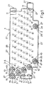
- Figs. 1 and 2 show a keyboard base member in the form of a baseboard 1 made from ABS plastics material.
- the baseboard 1 has a corresponding upstanding projection 3 (seven of which are indicated in Fig. 1). Further similar projections 3 are centred at the points B in Fig. 1,-there being five rows of projections.
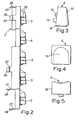
- the forty-three projections 3 in the four uppermost rows define the positions for keys 4 (one of which is shown in Figs. 3 to 6).
- the two widely-spaced projections 3 adjacent to the lowermost edge of the baseborad 1 are provided to receive a space bar key 5 (see Figs. 7 to 9).
- each projection 3 has a boss-like base 6, from which projects a central formation 7.
- the central formation 7 of each projection 3 is provided with a cylindrical hole 8, and a substantially rectangular-section hole 9 adjacent to the cylindrical hole.
- the rectangular hole 9 tapers downwardly along one edge 19, from its mouth towards the base 6.
- the central formation 7 of each projection 3 is strengthened by three ribs 10.
- the base of the hole 9 of each projection 3 has an angled recess 12.
- each key 4 has a slightly recessed top surface 13, from the underside of which projects a cylindrical spigot 14 and a lug 15 of generally rectangular cross-section.
- the spigot 14 and the lug 15 of each key 4 are surrounded by a peripheral wall 16 of that key.
- the extremity of each lug 15 is formed with a lip 17 (see Fig. 6).
- Each key 4 is pushed into position on its corresponding projection 3, with the interposition of a coil compression spring 18 -(see Fig. 6) which acts to urge that key towards its raised position, and to provide a spring return action for that key.
- a coil compression spring 18 - (see Fig. 6) which acts to urge that key towards its raised position, and to provide a spring return action for that key.
- the key 4 is then simply pushed into position so that its spigot 14 passes down the hole 8, and its lug 15 passes down the hole 9.
- As the lug moves into the hole 9 its lip 17 rides down the tapered edge 19 of that hole until its lip 17 springs with a snap action within the recess 12.
- the key 4 is then located in position on its corresponding projection 3 in the manner illustrated in Fig. 6. All forty-three keys 4 are pushed into position
- the space bar key 5 (see Figs 7 to 9) is symmetrical about the centre line C-C. Towards each end, the bar 5 has a respective spigot 22 and a respective lug 23, the pair of spigots 22 and lugs 23 locating in two pairs of holes 24 and 25 in the two projections 3 adjacent to the lower edge of the baseboard 1.
- a coil compression spring (not shown, but similar to the springs 18) is positioned between each of these two projections 3 and the space bar key 5, in a similar manner to that described and illustrated with respect to Fig. 6 for the keys 4.
- the keys 4 and 5 which are made of high-impact polystyrene, can simply be pushed into position at their desired locations on the baseboard 1. This results in a compact, easily-handled sub-assembly in which the keys 4 and 5 are firmly held with respect to the baseboard 1, but which may be detached therefrom by springing back the lugs 15 and 23, if required.
- the baseboard 1 also has slots 11 for the passage of other keys such as tabulation keys and shift keys.
- the two projections 3 which locate the space bar key 5 are similar to the projections 3 which locate the keys 4, but have holes 24 and 25 which are a little larger than the holes 8 and 9.
- the baseboard 1 has a peripheral, upstanding lip 2 6 which gives the baseboard a tray-like appearance.
- the baseboard 1 Around its periphery, the baseboard 1 has eleven, integrally- moulded, downwardly-projecting lugs 27.
- Each lug 27 has an end ledge or lip 28 (see Fig. 2).
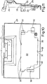
- the lugs 27 are provided to enable the sub-assembly of the baseboard 1, the keys 4 and 5 and the springs 18 to be snapped into position in a typewriter deck 29 (see Figs. 10 and 11).
- the deck 29, which is moulded from high-impact polystyrene, has a shallow recess 30 (see Fig. 10) shaped to receive the baseboard 1.
- the deck 29 also has eleven rectangular notches 32, which receive the respective lugs 27.
- the deck 29 also has a channel 33 for a typewriter ribbon cassette (not shown), and a portion (cut-away from Figs. 10 and 11) for covering a solenoid which drives a daisy wheel print head (not shown).
- the underside of the deck 29 has slotted projections 34 for the passage of keys such as tabulation keys and shift keys (or their operating levers).
- Fig. 12 shows a plastics sheet 35 carrying two printed circuits having nodes (such as 31 and 31a) at the locations of the short transverse lines printed on the circuitry.
- the sheet 35 is folded about the line D-D, so that the two printed circuits overlap, and a perforated insulating sheet 36 (see Fig. 13) is interposed between the two printed circuits.
- the folded sheet Locates accurately in the recess 30 in the deck 29, the portions 37 of the sheet 35 being passed through a slot 38 (see Fig. 11) in the deck 29 to enable the printed circuits to be electrically connected to circuitry for detecting which keys of the keyboard are depressed.
- the keyboard is assembled by folding the sheet 35 around the perforated sheet 36, and by laying the sheets in the recess 30. This automatically positions each of the perforations in the insulating sheet 36 between a respective pair of overlapping nodes such as 31 and 31a.
- the sub-assembly of the baseboard 1, the keys 4 and 5 and the springs 18 are then snapped into position, the lips 28 engaging with a snap action behind the notches 3 2.
- This automatically aligns the lower end of each key spigot 14 with a corresponding pair of nodes such as 31 and 31a, with the result that depression of the corresponding key 4 causes the nodes 31 and 31a to make contact through the corresponding perforation in the insulating sheet 36.
- the electrical connection of the nodes 31 and 31a is sensed, and the solenoid moves the. daisy wheel print head to the appropriate location. It will be appreciated that the insulating sheet 36 holds apart all pairs of overlapping nodes other than the pair of nodes pressed together by the depression of a given key 4.
- the keyboard sub-assembly described above has a number of important advantages, particularly when used as part of a toy typewriter.
- the baseboard and the keys are easy and cheap to make, as they can be moulded from cheap plastics materials.
- the keyboard sub-assembly can be assembled easily and quickly by snapping the keys into position on the baseboard, and the sub-assembly can easily be snapped into position on the deck of a toy typewriter. Once assembled, the keys shround the projections provided on the baseboard, and thus prevent foreign matter reaching the underside of the baseboard, where the electrical circuitry is positioned.
- the keyboard sub-assembly is particularly efficient at preventing liquids spilled on or around the keys from reaching the underside of the baseboard. This is because of the labyrinth-like interconnected spaces between the projections, and the tray-like formation of the baseboard. Thus, any spilled liquid is directed by the skirts of the keys onto the upper surface of the baseboard, the entire area of which is available for collecting the liquid.
- lugs and spigots beneath the keys.
- the cylindrical formation of the spigots permit the keys to be freely mounted for movement between their raised and depressed positions within the corresponding holes in the upstanding projections. This permits the keys to be raised and depressed without substantial risk of jamming.
- the generally rectangular formation of the lugs (and the associated lips) constitutes a very simple arrangement for snapping the keys into position on the baseboard.
- the particular formation of the lugs and spigot enables the keys to be formed in a single, simple moulding operation. This is to be contrasted with the keys of known assemblies, which require complicated and multiple moulding operations.
Landscapes
- Input From Keyboards Or The Like (AREA)
- Accessory Devices And Overall Control Thereof (AREA)
Applications Claiming Priority (2)
| Application Number | Priority Date | Filing Date | Title |
|---|---|---|---|
| GB8221206 | 1982-07-22 | ||
| GB8221206 | 1982-07-22 |
Publications (2)
| Publication Number | Publication Date |
|---|---|
| EP0101208A2 true EP0101208A2 (de) | 1984-02-22 |
| EP0101208A3 EP0101208A3 (de) | 1984-07-18 |
Family
ID=10531834
Family Applications (1)
| Application Number | Title | Priority Date | Filing Date |
|---|---|---|---|
| EP83304210A Withdrawn EP0101208A3 (de) | 1982-07-22 | 1983-07-20 | Tastatur |
Country Status (2)
| Country | Link |
|---|---|
| EP (1) | EP0101208A3 (de) |
| GB (1) | GB2124156A (de) |
Cited By (2)
| Publication number | Priority date | Publication date | Assignee | Title |
|---|---|---|---|---|
| GB2191040A (en) * | 1986-05-28 | 1987-12-02 | Plessey Co Plc | Keypad assemblies |
| DE8808164U1 (de) * | 1988-06-24 | 1988-08-25 | Limax Electronics Co., Ltd., Shen-Keng Hsiang, Taipei | Einen Rechner mit einem Puzzlespiel kombinierende Vorrichtung |
Families Citing this family (6)
| Publication number | Priority date | Publication date | Assignee | Title |
|---|---|---|---|---|
| DE3722616A1 (de) * | 1987-07-09 | 1989-01-19 | Triumph Adler Ag | Tastatur fuer schreib- oder aehnliche maschinen |
| DE8716377U1 (de) * | 1987-12-11 | 1989-04-13 | Diehl GmbH & Co, 90478 Nürnberg | Tastentableau für elektrische Geräte |
| GB8929007D0 (en) * | 1989-12-22 | 1990-02-28 | Starpoint Electrics Ltd | Push button switch mounting |
| US5172990A (en) * | 1991-05-23 | 1992-12-22 | Cal-Comp Electronics, Inc. | Structures of push - button key of keyboard |
| US5253142A (en) * | 1991-09-19 | 1993-10-12 | Cal-Comp Electronics, Inc. | Body structure for a pocket computer having a fastener with multiple spaced apart elements |
| US5209588A (en) * | 1992-06-09 | 1993-05-11 | Chen Pao Chin | Computer key switch |
Family Cites Families (6)
| Publication number | Priority date | Publication date | Assignee | Title |
|---|---|---|---|---|
| CH479911A (de) * | 1968-03-26 | 1969-10-15 | Anker Werke Ag | Wert- und Funktionseinstelleinrichtung an rechnenden Geschäftsmaschinen |
| US3993884A (en) * | 1972-09-15 | 1976-11-23 | Victor Comptometer Corporation | Detachably mounted keyboard pushbutton actuators and housing assembly |
| US3856998A (en) * | 1973-06-01 | 1974-12-24 | Burroughs Corp | Keyboard switch assembly with improved operating means |
| US4274752A (en) * | 1979-04-02 | 1981-06-23 | International Business Machines Corporation | Keyboard multiple switch assembly |
| US4292516A (en) * | 1979-09-14 | 1981-09-29 | Burroughs Corporation | Photo-optical keyboard having debris protection |
| DE3007239C2 (de) * | 1980-02-27 | 1985-02-07 | Standard Elektrik Lorenz Ag, 7000 Stuttgart | Tastatur mit einer Vielzahl von Tastengliedern |
-
1983
- 1983-07-20 GB GB08319634A patent/GB2124156A/en not_active Withdrawn
- 1983-07-20 EP EP83304210A patent/EP0101208A3/de not_active Withdrawn
Cited By (3)
| Publication number | Priority date | Publication date | Assignee | Title |
|---|---|---|---|---|
| GB2191040A (en) * | 1986-05-28 | 1987-12-02 | Plessey Co Plc | Keypad assemblies |
| GB2191040B (en) * | 1986-05-28 | 1990-04-18 | Plessey Co Plc | Keypad assemblies |
| DE8808164U1 (de) * | 1988-06-24 | 1988-08-25 | Limax Electronics Co., Ltd., Shen-Keng Hsiang, Taipei | Einen Rechner mit einem Puzzlespiel kombinierende Vorrichtung |
Also Published As
| Publication number | Publication date |
|---|---|
| GB8319634D0 (en) | 1983-08-24 |
| GB2124156A (en) | 1984-02-15 |
| EP0101208A3 (de) | 1984-07-18 |
Similar Documents
| Publication | Publication Date | Title |
|---|---|---|
| EP0277404B1 (de) | Tastenfeld mit niedrigem Gehäuse mit angeformtem erhobenem Teil zum Tragen einer Leiterplatte | |
| AU666143B2 (en) | Computer keyboard with cantilever switch design and improved PCB/switch membrane interface | |
| EP0101208A2 (de) | Tastatur | |
| US5481074A (en) | Computer keyboard with cantilever switch and actuator design | |
| US4325645A (en) | Inked ribbon cartridge having a guide plate | |
| US4440515A (en) | Keybar keyboard | |
| US4479111A (en) | Photo-optical switch apparatus | |
| US5193924A (en) | Cap cover for keyboard keys | |
| JPH09120748A (ja) | キー組立体 | |
| JPH0425652B2 (de) | ||
| JPH0624087B2 (ja) | ハンドルパツド・キ−ボ−ドスイツチ組立体 | |
| US5907612A (en) | Removable button for a keypad | |
| JPH0216486Y2 (de) | ||
| US4778295A (en) | Keyboard with elongate keys associated with compact switch mechanisms | |
| US3693775A (en) | Actuator for elastic diaphragm switch keyboard | |
| US4292517A (en) | Photo-optical keyboard providing tactile feel | |
| EP1065686B1 (de) | Satz zum Entwurf Bedienungsfelder mit mehreren Konfigurationen für Bürogeräte | |
| US4349286A (en) | Keyboard assembled from individual keys | |
| US4855548A (en) | Keybutton guide assembly for a keyboard | |
| US4135074A (en) | Automatic keyboard operator | |
| US4594481A (en) | Electronic touch pad key assembly with stroke amplifier | |
| EP1327508A2 (de) | Lochstanze | |
| WO1981000773A1 (en) | Photo-optical keyboard having n-key rollover | |
| GB2207000A (en) | Keyboards | |
| US4292516A (en) | Photo-optical keyboard having debris protection |
Legal Events
| Date | Code | Title | Description |
|---|---|---|---|
| PUAI | Public reference made under article 153(3) epc to a published international application that has entered the european phase |
Free format text: ORIGINAL CODE: 0009012 |
|
| AK | Designated contracting states |
Designated state(s): BE CH DE FR GB IT LI LU |
|
| PUAL | Search report despatched |
Free format text: ORIGINAL CODE: 0009013 |
|
| AK | Designated contracting states |
Designated state(s): BE CH DE FR GB IT LI LU |
|
| RAP1 | Party data changed (applicant data changed or rights of an application transferred) |
Owner name: SPIRALUX LIMITED |
|
| STAA | Information on the status of an ep patent application or granted ep patent |
Free format text: STATUS: THE APPLICATION IS DEEMED TO BE WITHDRAWN |
|
| 18D | Application deemed to be withdrawn |
Effective date: 19850319 |
|
| RIN1 | Information on inventor provided before grant (corrected) |
Inventor name: WRIGHT, RAYMOND GRENVILLE WHITEHEAD |