EP0101531A2 - Dispositif d'aiguillage aux microondes comportant un émetteur ou un récepteur auxiliaire - Google Patents
Dispositif d'aiguillage aux microondes comportant un émetteur ou un récepteur auxiliaire Download PDFInfo
- Publication number
- EP0101531A2 EP0101531A2 EP83104053A EP83104053A EP0101531A2 EP 0101531 A2 EP0101531 A2 EP 0101531A2 EP 83104053 A EP83104053 A EP 83104053A EP 83104053 A EP83104053 A EP 83104053A EP 0101531 A2 EP0101531 A2 EP 0101531A2
- Authority
- EP
- European Patent Office
- Prior art keywords
- reserve
- receiver
- transmitter
- transmitters
- antenna
- Prior art date
- Legal status (The legal status is an assumption and is not a legal conclusion. Google has not performed a legal analysis and makes no representation as to the accuracy of the status listed.)
- Granted
Links
- 230000010287 polarization Effects 0.000 description 6
- 241000270281 Coluber constrictor Species 0.000 description 1
- 230000000712 assembly Effects 0.000 description 1
- 238000000429 assembly Methods 0.000 description 1
- 230000005540 biological transmission Effects 0.000 description 1
- OQZCSNDVOWYALR-UHFFFAOYSA-N flurochloridone Chemical compound FC(F)(F)C1=CC=CC(N2C(C(Cl)C(CCl)C2)=O)=C1 OQZCSNDVOWYALR-UHFFFAOYSA-N 0.000 description 1
- 230000001681 protective effect Effects 0.000 description 1
- 238000011144 upstream manufacturing Methods 0.000 description 1
Images
Classifications
-
- H—ELECTRICITY
- H01—ELECTRIC ELEMENTS
- H01P—WAVEGUIDES; RESONATORS, LINES, OR OTHER DEVICES OF THE WAVEGUIDE TYPE
- H01P1/00—Auxiliary devices
- H01P1/20—Frequency-selective devices, e.g. filters
- H01P1/213—Frequency-selective devices, e.g. filters combining or separating two or more different frequencies
-
- H—ELECTRICITY
- H04—ELECTRIC COMMUNICATION TECHNIQUE
- H04B—TRANSMISSION
- H04B1/00—Details of transmission systems, not covered by a single one of groups H04B3/00 - H04B13/00; Details of transmission systems not characterised by the medium used for transmission
- H04B1/74—Details of transmission systems, not covered by a single one of groups H04B3/00 - H04B13/00; Details of transmission systems not characterised by the medium used for transmission for increasing reliability, e.g. using redundant or spare channels or apparatus
Definitions
- the present invention relates to a microwave switch arrangement with chain-connected circulators for connecting a plurality of transmitters or receivers, which are each assigned to different frequency channels, to a common antenna, at least one reserve transmitter or reserve receiver being available for a failed device the antenna can be switched.
- switch assemblies are to be provided with reserve devices that can be switched through to the antenna instead of failed transmitters or receivers.
- n + 1 line replacement circuit An example of the wiring of a microwave switch arrangement with a reserve transmitter or receiver, a so-called n + 1 line replacement circuit, can be found in the AEG-TELEFUNKEN long-distance traffic and cable technology brochure, "Protective circuit device SSG n + 1 for broadband directional radio systems "11.76, there.
- the reserve device like the other transmitters or receivers, is connected to one of the switches connected in a chain (circulators). In the event of a fault in one of the operating devices, the signal to be transmitted becomes the base frequency or the intermediate frequency level is switched to the reserve device.
- Racer device is operated on a frequency channel not yet occupied by the other transmitters or receivers.
- the invention is therefore based on the object of wiring a microwave switch arrangement of the type mentioned at the outset with at least one reserve transmitter or receiver, for which no separate frequency channel has to be provided.
- This object is achieved in that for each reserve transmitter or reserve receiver, an additional circulator is inserted in the signal path between the antenna and the first circulator connected to one of the transmitters or receivers, on its free arm, which is completely reflective in normal operation,
- the reserve device can be connected via a switch and that the reserve device can be tuned to the frequency channel of the transmitter or receiver to be replaced in each case.
- An advantage of the circuit according to the invention is that you can usually use a reserve transmitter or a reserve receiver ger gets along and that without interrupting the signal path the reserve device is switched through to the antenna and this switch can be expanded by several transmitters or receivers.
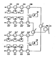
- the switch arrangement shown in the figure has a circulator chain ZS1, ZS2, ZS3 for connecting the transmitters S1, S2, S3 and a circulator chain ZE2, ZE2, ZE3 for connecting the receivers E1, E2, E3 to an antenna A.
- Each transmitter and receiver is assigned to another frequency channel.
- the transmitting and receiving switch train are connected to the antenna together via a circulator Z.
- the switch arrangement can be optimally used if, as the figure shows, transmit and receive switch trains are available for two orthogonal polarizations.
- the transmission and reception switch trains for the one polarization which have just been interconnected via the circulator Z are for the other polarization the transmitter switch train ZS1 ', ZS2', ZS3 'with the transmitters S1', S2 ', S3' and the reception switch train ZE1 ', ZE2' , ZE3 'with the receivers E1', E2 ', E3' added, both of which are brought together at a circulator Z '.
- a polarization switch PW upstream of the antenna assigns the corresponding polarizations to the individual switch trains.
- Each of the switch trains is extended towards the antenna by an additional circulator ZSR, ZSR ', ZER, ZER'.
- additional circulators serve to connect a reserve transmitter SR or a reserve receiver ER to antenna A.
- the free arm of the respective additional circulator is totally reflective (e.g. short circuit or or idle) completed.
- the free arm of the additional circulator inserted in the faulty switch train is switched to a reserve device SR or ER via a switch SCH.
- a mechanical switch or, even better, an electronically controllable, for example pin-diode switch, can be used for this purpose.
- a reserve transmitter can be used instead of one of the transmitters S1, S2, S3 in one branch and instead of one of the transmitters S1 ', S2', S3 'in the other branch connected to the antenna.
- the reserve receiver which is available for the receivers E1, E2, E3, El ', E2', E3 'of both reception switch trains.
- the reserve transmitter SR and the reserve receiver ER can be matched to the frequency channel of the transmitter or receiver that you are about to replace.-The two reserve devices therefore have either a filter that can be tuned across all frequency channels or a filter battery with filters that are permanently matched to the individual frequency channels . The reserve devices therefore occupy no other frequency channels than those assigned to the transmitters and receivers.
- the additional circulators for the reserve devices between the antenna and the first circulator must be inserted into the circulator chain responsible for connecting the transmitters and receivers.
Landscapes
- Engineering & Computer Science (AREA)
- Computer Networks & Wireless Communication (AREA)
- Signal Processing (AREA)
- Transmitters (AREA)
- Radio Relay Systems (AREA)
- Radar Systems Or Details Thereof (AREA)
- Input Circuits Of Receivers And Coupling Of Receivers And Audio Equipment (AREA)
- Transceivers (AREA)
Priority Applications (1)
| Application Number | Priority Date | Filing Date | Title |
|---|---|---|---|
| AT83104053T ATE36103T1 (de) | 1982-07-16 | 1983-04-26 | Mikrowellen-weichenanordnung mit sender- bzw. empfaengerersatzschaltung. |
Applications Claiming Priority (2)
| Application Number | Priority Date | Filing Date | Title |
|---|---|---|---|
| DE19823226728 DE3226728A1 (de) | 1982-07-16 | 1982-07-16 | Mikrowellen-weichenanordnung mit sender- bzw. empfaengerersatzschaltung |
| DE3226728 | 1982-07-16 |
Publications (3)
| Publication Number | Publication Date |
|---|---|
| EP0101531A2 true EP0101531A2 (fr) | 1984-02-29 |
| EP0101531A3 EP0101531A3 (en) | 1986-03-12 |
| EP0101531B1 EP0101531B1 (fr) | 1988-07-27 |
Family
ID=6168625
Family Applications (1)
| Application Number | Title | Priority Date | Filing Date |
|---|---|---|---|
| EP83104053A Expired EP0101531B1 (fr) | 1982-07-16 | 1983-04-26 | Dispositif d'aiguillage aux microondes comportant un émetteur ou un récepteur auxiliaire |
Country Status (3)
| Country | Link |
|---|---|
| EP (1) | EP0101531B1 (fr) |
| AT (1) | ATE36103T1 (fr) |
| DE (2) | DE3226728A1 (fr) |
Cited By (6)
| Publication number | Priority date | Publication date | Assignee | Title |
|---|---|---|---|---|
| EP0293099A1 (fr) * | 1987-05-14 | 1988-11-30 | Hazeltine Corporation | Système d'aterrissage à micro-ondes à balayage de faisceaux à des antennes à secteurs et mise en circuit en mode dégradé d'un émetteur de réserve |
| EP0338471A3 (en) * | 1988-04-18 | 1990-09-12 | Nokia-Mobira Oy | A dividing cascade network for a support station in a radio telephone network |
| WO1996000989A1 (fr) * | 1994-06-30 | 1996-01-11 | Nokia Telecommunications Oy | Reseau de sommation |
| EP0677884A3 (fr) * | 1994-03-31 | 1996-08-07 | Ant Nachrichtentech | Multiplexeur et demultiplexeur de canaux fréquentiels. |
| WO2000038341A1 (fr) * | 1998-12-22 | 2000-06-29 | Telefonaktiebolaget Lm Ericsson (Publ) | Module de commutation d'antenne |
| RU2218663C2 (ru) * | 2001-11-29 | 2003-12-10 | Открытое акционерное общество "Радиофизика" | Станция приемопередающая |
Families Citing this family (1)
| Publication number | Priority date | Publication date | Assignee | Title |
|---|---|---|---|---|
| DE3632984A1 (de) * | 1986-09-29 | 1988-04-07 | Ant Nachrichtentech | Anordnung zum aufschalten mehrerer sender und empfaenger auf eine antenne |
Family Cites Families (3)
| Publication number | Priority date | Publication date | Assignee | Title |
|---|---|---|---|---|
| DE1068775B (de) * | 1959-03-21 | 1959-11-12 | Telefunken G.M.B.H., Berlin | Umschalteinrichtung für Mikrowellengeräte |
| DE2213962C3 (de) * | 1972-03-22 | 1979-01-18 | Siemens Ag, 1000 Berlin Und 8000 Muenchen | Funkfeld in einem Richtfunksystem |
| DE2641875C2 (de) * | 1976-09-17 | 1978-11-16 | Licentia Patent-Verwaltungs-Gmbh, 6000 Frankfurt | Mikrowellen-Weichenanordnung mit in Kette geschalteten Dreiarm-Zirkulatoren zum Auf schalten von mehreren Sendern und Empfängern auf eine gemeinsame Antenne |
-
1982
- 1982-07-16 DE DE19823226728 patent/DE3226728A1/de not_active Withdrawn
-
1983
- 1983-04-26 AT AT83104053T patent/ATE36103T1/de not_active IP Right Cessation
- 1983-04-26 DE DE8383104053T patent/DE3377561D1/de not_active Expired
- 1983-04-26 EP EP83104053A patent/EP0101531B1/fr not_active Expired
Cited By (9)
| Publication number | Priority date | Publication date | Assignee | Title |
|---|---|---|---|---|
| EP0293099A1 (fr) * | 1987-05-14 | 1988-11-30 | Hazeltine Corporation | Système d'aterrissage à micro-ondes à balayage de faisceaux à des antennes à secteurs et mise en circuit en mode dégradé d'un émetteur de réserve |
| EP0338471A3 (en) * | 1988-04-18 | 1990-09-12 | Nokia-Mobira Oy | A dividing cascade network for a support station in a radio telephone network |
| EP0677884A3 (fr) * | 1994-03-31 | 1996-08-07 | Ant Nachrichtentech | Multiplexeur et demultiplexeur de canaux fréquentiels. |
| US5691987A (en) * | 1994-03-31 | 1997-11-25 | Ant Nachrichtentechnik Gmbh | Frequency-channel multiplexer and demultiplexer |
| WO1996000989A1 (fr) * | 1994-06-30 | 1996-01-11 | Nokia Telecommunications Oy | Reseau de sommation |
| US5689219A (en) * | 1994-06-30 | 1997-11-18 | Nokia Telecommunications Oy | Summing network |
| WO2000038341A1 (fr) * | 1998-12-22 | 2000-06-29 | Telefonaktiebolaget Lm Ericsson (Publ) | Module de commutation d'antenne |
| US6560444B1 (en) | 1998-12-22 | 2003-05-06 | Telefonaktiebolaget Lm Ericsson (Publ) | Antenna switch module |
| RU2218663C2 (ru) * | 2001-11-29 | 2003-12-10 | Открытое акционерное общество "Радиофизика" | Станция приемопередающая |
Also Published As
| Publication number | Publication date |
|---|---|
| DE3377561D1 (en) | 1988-09-01 |
| ATE36103T1 (de) | 1988-08-15 |
| DE3226728A1 (de) | 1984-01-19 |
| EP0101531A3 (en) | 1986-03-12 |
| EP0101531B1 (fr) | 1988-07-27 |
Similar Documents
| Publication | Publication Date | Title |
|---|---|---|
| DE69430633T2 (de) | Verfahren zur sicherung des betriebs einer basisstation | |
| DE69933559T2 (de) | Optisches wdm netzwerk mit effizientem gebrauch der wellenlänge und knoten dafür verwendeter | |
| DE3637016C2 (fr) | ||
| DE2844776A1 (de) | Sender-multiplexsystem fuer ein bewegliches uebertragungssystem | |
| DE2213962A1 (de) | Funkfeld in einem richtfunksystem | |
| EP0101531B1 (fr) | Dispositif d'aiguillage aux microondes comportant un émetteur ou un récepteur auxiliaire | |
| DE2628906C2 (de) | Funkfeld in einer Richtfunkstrecke | |
| DE19733760C2 (de) | Datenbusleitung mit Sende- und Empfangskomponenten | |
| DE3642378C2 (fr) | ||
| EP0111582B1 (fr) | Dispositif pour la localisation des dérangements d'une liaison par câble à fibres optiques | |
| DE2459045C3 (de) | Ankopplungs-Vorrichtung | |
| DE3784643T2 (de) | Funksenderempfaengersystem zur erhoehung oder zur verringerung der uebertragungskanaele. | |
| DE19831562A1 (de) | Verfahren und Vorrichtung zur Effektivierung der Übertragungs- und Ausfallsicherheit in hochbitratigen Datennetzen | |
| EP0262391B1 (fr) | Dispositif de branchement de plusieurs émetteurs et récepteurs à une antenne | |
| EP1151568B1 (fr) | Noeud de reseau comprenant des modules d'insertion-extraction optiques | |
| DE68917534T2 (de) | Datenpfadschutz. | |
| DE1912791A1 (de) | Langstrecken-Richtfunkanlage | |
| EP0104485B1 (fr) | Système pour la transmission d'informations | |
| EP0479768B1 (fr) | Méthode pour la gestion de canaux radio | |
| DE4017403C1 (en) | Frequency multiplexing transmission system for satellite - selects mixing frequency signals so that frequency bands overlap by one channel | |
| CH615545A5 (en) | Tunnel radio system | |
| DE10316743A1 (de) | Datenübertragungseinrichtung für einen Wagenverbund | |
| DE19521215A1 (de) | Anordnung zur Übertragung, zur Abstrahlung und zum Empfang von Hochfrequenz-Signalen | |
| WO1996007138A1 (fr) | Circuit equivalent pour plusieurs unites fonctionnelles | |
| DE850769C (de) | Anordnung der Leitungsfilter beim gleichzeitigen Betrieb mehrerer Traegerstromsysteme auf einer UEbertragungsleitung |
Legal Events
| Date | Code | Title | Description |
|---|---|---|---|
| PUAI | Public reference made under article 153(3) epc to a published international application that has entered the european phase |
Free format text: ORIGINAL CODE: 0009012 |
|
| AK | Designated contracting states |
Designated state(s): AT BE CH DE FR GB LI LU NL SE |
|
| PUAL | Search report despatched |
Free format text: ORIGINAL CODE: 0009013 |
|
| AK | Designated contracting states |
Kind code of ref document: A3 Designated state(s): AT BE CH DE FR GB LI LU NL SE |
|
| 17P | Request for examination filed |
Effective date: 19860403 |
|
| 17Q | First examination report despatched |
Effective date: 19870820 |
|
| GRAA | (expected) grant |
Free format text: ORIGINAL CODE: 0009210 |
|
| AK | Designated contracting states |
Kind code of ref document: B1 Designated state(s): AT BE CH DE FR GB LI LU NL SE |
|
| REF | Corresponds to: |
Ref document number: 36103 Country of ref document: AT Date of ref document: 19880815 Kind code of ref document: T |
|
| REF | Corresponds to: |
Ref document number: 3377561 Country of ref document: DE Date of ref document: 19880901 |
|
| GBT | Gb: translation of ep patent filed (gb section 77(6)(a)/1977) | ||
| ET | Fr: translation filed | ||
| PGFP | Annual fee paid to national office [announced via postgrant information from national office to epo] |
Ref country code: LU Payment date: 19890322 Year of fee payment: 7 |
|
| PGFP | Annual fee paid to national office [announced via postgrant information from national office to epo] |
Ref country code: FR Payment date: 19890413 Year of fee payment: 7 |
|
| PGFP | Annual fee paid to national office [announced via postgrant information from national office to epo] |
Ref country code: SE Payment date: 19890420 Year of fee payment: 7 |
|
| PGFP | Annual fee paid to national office [announced via postgrant information from national office to epo] |
Ref country code: AT Payment date: 19890424 Year of fee payment: 7 |
|
| PG25 | Lapsed in a contracting state [announced via postgrant information from national office to epo] |
Ref country code: LU Free format text: LAPSE BECAUSE OF NON-PAYMENT OF DUE FEES Effective date: 19890430 |
|
| PGFP | Annual fee paid to national office [announced via postgrant information from national office to epo] |
Ref country code: NL Payment date: 19890430 Year of fee payment: 7 Ref country code: GB Payment date: 19890430 Year of fee payment: 7 |
|
| PGFP | Annual fee paid to national office [announced via postgrant information from national office to epo] |
Ref country code: BE Payment date: 19890523 Year of fee payment: 7 |
|
| PLBE | No opposition filed within time limit |
Free format text: ORIGINAL CODE: 0009261 |
|
| STAA | Information on the status of an ep patent application or granted ep patent |
Free format text: STATUS: NO OPPOSITION FILED WITHIN TIME LIMIT |
|
| PGFP | Annual fee paid to national office [announced via postgrant information from national office to epo] |
Ref country code: DE Payment date: 19890612 Year of fee payment: 7 |
|
| 26N | No opposition filed | ||
| PGFP | Annual fee paid to national office [announced via postgrant information from national office to epo] |
Ref country code: CH Payment date: 19890717 Year of fee payment: 7 |
|
| PG25 | Lapsed in a contracting state [announced via postgrant information from national office to epo] |
Ref country code: GB Effective date: 19900426 Ref country code: AT Effective date: 19900426 |
|
| PG25 | Lapsed in a contracting state [announced via postgrant information from national office to epo] |
Ref country code: SE Effective date: 19900427 |
|
| PG25 | Lapsed in a contracting state [announced via postgrant information from national office to epo] |
Ref country code: LI Effective date: 19900430 Ref country code: CH Effective date: 19900430 Ref country code: BE Effective date: 19900430 |
|
| BERE | Be: lapsed |
Owner name: ANT NACHRICHTENTECHNIK G.M.B.H. Effective date: 19900430 |
|
| PG25 | Lapsed in a contracting state [announced via postgrant information from national office to epo] |
Ref country code: NL Effective date: 19901101 |
|
| NLV4 | Nl: lapsed or anulled due to non-payment of the annual fee | ||
| PG25 | Lapsed in a contracting state [announced via postgrant information from national office to epo] |
Ref country code: FR Effective date: 19901228 |
|
| REG | Reference to a national code |
Ref country code: CH Ref legal event code: PL |
|
| PG25 | Lapsed in a contracting state [announced via postgrant information from national office to epo] |
Ref country code: DE Effective date: 19910101 |
|
| GBPC | Gb: european patent ceased through non-payment of renewal fee | ||
| REG | Reference to a national code |
Ref country code: FR Ref legal event code: ST |
|
| EUG | Se: european patent has lapsed |
Ref document number: 83104053.0 Effective date: 19910115 |