EP0101568A2 - Konstruktion zum Anbringen von Teppichstoff im Fahrzeugaufbau - Google Patents
Konstruktion zum Anbringen von Teppichstoff im Fahrzeugaufbau Download PDFInfo
- Publication number
- EP0101568A2 EP0101568A2 EP83107226A EP83107226A EP0101568A2 EP 0101568 A2 EP0101568 A2 EP 0101568A2 EP 83107226 A EP83107226 A EP 83107226A EP 83107226 A EP83107226 A EP 83107226A EP 0101568 A2 EP0101568 A2 EP 0101568A2
- Authority
- EP
- European Patent Office
- Prior art keywords
- support member
- floor
- pillar garnish
- carpeting
- carpet
- Prior art date
- Legal status (The legal status is an assumption and is not a legal conclusion. Google has not performed a legal analysis and makes no representation as to the accuracy of the status listed.)
- Withdrawn
Links
Images


Classifications
-
- B—PERFORMING OPERATIONS; TRANSPORTING
- B60—VEHICLES IN GENERAL
- B60N—SEATS SPECIALLY ADAPTED FOR VEHICLES; VEHICLE PASSENGER ACCOMMODATION NOT OTHERWISE PROVIDED FOR
- B60N3/00—Arrangements or adaptations of other passenger fittings, not otherwise provided for
- B60N3/04—Arrangements or adaptations of other passenger fittings, not otherwise provided for of floor mats or carpets
- B60N3/046—Arrangements or adaptations of other passenger fittings, not otherwise provided for of floor mats or carpets characterised by the fixing means
-
- Y—GENERAL TAGGING OF NEW TECHNOLOGICAL DEVELOPMENTS; GENERAL TAGGING OF CROSS-SECTIONAL TECHNOLOGIES SPANNING OVER SEVERAL SECTIONS OF THE IPC; TECHNICAL SUBJECTS COVERED BY FORMER USPC CROSS-REFERENCE ART COLLECTIONS [XRACs] AND DIGESTS
- Y10—TECHNICAL SUBJECTS COVERED BY FORMER USPC
- Y10T—TECHNICAL SUBJECTS COVERED BY FORMER US CLASSIFICATION
- Y10T403/00—Joints and connections
- Y10T403/16—Joints and connections with adjunctive protector, broken parts retainer, repair, assembly or disassembly feature
- Y10T403/1608—Holding means or protector functioning only during transportation, assembly or disassembly
Definitions
- a carpet support member is located so as to bridge the space between a floor panel and the upper edge ' of the side sill outer panel.
- An enclosed space is, therefore, defined below the carpet support member in conjunction with the floor panel and side sill inner panel.
- An electrical wire harness runs through this space.
- a cut- out of substantially trapezoidal shape is provided along one edge of the carpet support member and onto the sloping surface thereof opposite the lower end of a center pillar garnish described hereinafter.
- a layer of floor carpeting rests on the carpet support member.
- the center pillar garnish is mounted so as to cover the center pillar inner member.
- the lower end of the center pillar garnish is substantially trapezoidal.
- the inner surface of the lower end of the center pillar garnish is brought into close contact with the floor carpeting over the cutout of the carpet support member.
- the edge of the floor carpeting other than the portion enclosed by the lower end of the center pillar garnish is enclosed by a kicking plate. It should also be noted that the distance between the lower end of the center pillar garnish and the carpet support member is previously designed to be narrower than the thickness of ordinary floor carpeting. Care is taken to prevent a gap from occurring between the floor carpeting and the lower end of the center pillar garnish. Therefore, the portion of the floor carpeting which is positioned over the cutout of the carpet support member is depressed into the cutout due to the force applied by the trapezoidal lower end of the center pillar garnish when the center pillar garnish is mounted on the center pillar inner member.
- the contact area between the lower end of the center pillar garnish and the floor carpeting is accordingly reduced, the reactive force of the floor carpeting against the center pillar garnish is reduced, so that the center pillar garnish can be easily installed in its intended position on the center pillar inner member and the floor carpet rests properly on the carpet support member while remaining clamped in place by the lower end of the center pillar garnish. Consequently, the floor carpet can fixedly be attached to the floor panel and carpet support member.
- Fig. 1 shows a conventional structure of a ' vehicle body for attaching floor carpeting, in particular the periphery of a center pillar.
- a pillar garnish such as a center pillar garnish and the floor carpeting itself are omitted from Fig. 1.
- Fig. 2 shows the conventional structure of the vehicle body for attaching the floor carpeting.
- the center pillar garnish and the floor carpeting are both installed in place over a corresponding panel of the vehicle body.
- numeral 1 denotes a floor panel of the vehicle body and numeral 2 denotes a side sill inner panel elongated along the vehicle body.
- the floor panel 1 is bent downwards along one longitudinal edge and is fixed to the lower edge of the side sill inner panel 2.
- Numeral 3 denotes a side sill outer panel, to opposite sides of the inside, upper edge of which the upper edge of the side sill inner panel 2 and the lower end of a center pillar inner member 4 are fixed and to the outside, upper edge of which the lower end of a center pillar outer member 5 is fixed.
- Numeral 6 denotes a carpet support member, the upper edge of which is fixed to the upper edge of the side sill inner panel 2 by means of screws 7 and lower end of which is fixed to the floor panel 1 by means of screws 7. Therefore, as best seen in Fig. 3 a space S of substantially a triangular shape in cross-section is formed .by these three members, i.e., side sill inner panel 2, floor panel 1, and floor carpet support member 6. An electrical wiring harness (not shown) runs through the space S.
- numeral 6' denotes a stopper member attached to the upper edge of the carpet support member 6 for securing the carpet support member 6 to the side sill inner panel 2.
- a cutout 8 of substantially trapezoidal shape is provided along the outside edge of the carpet support member 6, i.e., the edge adjacent to the lower end of the center pillar inner member 4.
- the bottom edge of the cutout 8 extends onto the sloping portion of the carpet support member 6, which face the lower end 10a of a center pillar garnish 10 to be described hereinafter.
- a floor carpet 9 rests on the floor panel 1 and on the carpet support member 6.
- An inner surface of the trapezoidal lower end 10a of the center pillar garnish 10 clamps part of the outside edge of the floor carpet 9 which rests on the cutout 8 provided in the carpet support member 6.
- the rest of the outside edge of the floor carpet 9 is later tightly clamped to the side sill inner panel 2 by means of a kicking plate (not shown).
- the clearance between the lower end 10a of the center pillar garnish 10 and the carpet support member 6 is previously selected to be narrower than the thickness of the floor carpet 9 so that the clearance is completely filled by the floor carpet 9 when the center pillar -garnish 10 is mounted on the center pillar inner member 4 . Therefore, the portion of the outside edge 9a of the floor carpet 9 which rests on the cutout 8 of the carpet support member 6 is pushed into the cutout 8.
- the area of contact between the carpet 9 and the lower end 10a of the center pillar garnish 10 is thus reduced so that the reactive force of the floor carpet 9 against the center pillar garnish 10 is accordingly reduced.
- the center pillar garnish 10 is fixed in place and the outside edge 9a of the floor carpet 9 is held in close contact with the upper surface of the carpet support member 6.
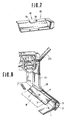
- numeral 16 denotes the carpet support member which in accordance with the present invention has sawteeth 19 provided along the edges of the conventional trapezoidal cutout 18.
- the base of each of the sawteeth 19 starts on the sloping surface of the carpet support member 16 at a point opposite to the lower edge of the lower end 10a of the center pillar garnish 10.
- the lower end 10a of the center pillar garnish 10 acts to clamp the outside edge 9a of the floor carpet 9 which rests on the sawteeth 19 provided around the cutout 18.
- a stooper member 16' is attached to the carpet support member 16.
- the carpet support member 16 is fixed to a point near the juncture of the side sill inner panel 2 and side sill outer panel 3 by means of the screws 7.
- the floor carpet 9 is layed over the carpet support member 16.
- the lower end 10a of the center pillar garnish 10 pushes against the portion of the floor carpet 9 which rests on the sawteeth 19 of the cutout 18 provided in the carpet support member 16.
- the sawteeth 19 tend to bend downward into the space S so that the reactive force between the lower end 10a of the center pillar garnish 10 and the carpet 9 is reduced.
- the center pillar garnish 10 can, thus, easily be fixed in place.
- Fig. 8 shows a second preferred embodiment according to the present invention.
- the cutout 18 edged with sawteeth 19 is located at one end of the outside edge of the carpet support member 16 opposite the lower end of a front pillar inner member 20.
- the outside edge 9a of the floor carpet 9 rests on the sawteeth 19 provided along the cutout 18.
- the lower end 21a of the front pillar garnish 21 clamps the portion of the floor carpet 9 facing the sawteeth 19 of the cutout 18.
- center pillar garnish 10 and front pillar garnish 21 as means for clamping the the floor carpet 9
- rear pillar garnish may obviously also be used for this purpose.
- sawteeth are provided around the edges of a cutout at the edge of a carpet support member extending between a side sill inner panel and a floor panel and the lower end of a pillar garnish is installed so as to compress a portion of the floor carpet against the sawteeth of the cutout. Therefore, relatively thin floor carpeting can be securely clamped in the clearance between the lower end of the pillar garnish and the carpet support member. In addition, thicker floor carpeting can also fit into the clearance since the sawteeth will bend to accommodate the floor carpet in response to the compression force of the pillar garnish and so the reactive force of the floor carpet against the lower end of a pillar garnish will also be reduced. Consequently, the pillar garnish can also easily be fitted into place.
Landscapes
- Engineering & Computer Science (AREA)
- Transportation (AREA)
- Mechanical Engineering (AREA)
- Body Structure For Vehicles (AREA)
- Vehicle Interior And Exterior Ornaments, Soundproofing, And Insulation (AREA)
- Passenger Equipment (AREA)
Applications Claiming Priority (2)
| Application Number | Priority Date | Filing Date | Title |
|---|---|---|---|
| JP57146184A JPS5938140A (ja) | 1982-08-25 | 1982-08-25 | 車両のフロアカ−ペツト取付構造 |
| JP146184/82 | 1982-08-25 |
Publications (2)
| Publication Number | Publication Date |
|---|---|
| EP0101568A2 true EP0101568A2 (de) | 1984-02-29 |
| EP0101568A3 EP0101568A3 (de) | 1987-08-19 |
Family
ID=15402032
Family Applications (1)
| Application Number | Title | Priority Date | Filing Date |
|---|---|---|---|
| EP83107226A Withdrawn EP0101568A3 (de) | 1982-08-25 | 1983-07-22 | Konstruktion zum Anbringen von Teppichstoff im Fahrzeugaufbau |
Country Status (3)
| Country | Link |
|---|---|
| US (1) | US4532671A (de) |
| EP (1) | EP0101568A3 (de) |
| JP (1) | JPS5938140A (de) |
Families Citing this family (3)
| Publication number | Priority date | Publication date | Assignee | Title |
|---|---|---|---|---|
| JPS61158572U (de) * | 1985-03-25 | 1986-10-01 | ||
| US5288121A (en) * | 1993-02-25 | 1994-02-22 | Grant Industries, Inc. | Automobile trim strip and carpet retaining clip |
| KR102664126B1 (ko) * | 2019-12-16 | 2024-05-09 | 현대자동차주식회사 | 차량용 사이드실구조 |
Family Cites Families (3)
| Publication number | Priority date | Publication date | Assignee | Title |
|---|---|---|---|---|
| US1206759A (en) * | 1916-05-22 | 1916-11-28 | Andreas Hanauer | Carpet anchor-clip. |
| DE7036510U (de) * | 1970-10-02 | 1971-02-04 | Opel Adam Ag | Vorrichtung zur befestigung des bodenbelages von fahrzeugen, insbesondere kraftfahrzeugen. |
| US4069542A (en) * | 1976-12-01 | 1978-01-24 | Carder William E | Carpet securing strips |
-
1982
- 1982-08-25 JP JP57146184A patent/JPS5938140A/ja active Pending
-
1983
- 1983-07-11 US US06/512,563 patent/US4532671A/en not_active Expired - Fee Related
- 1983-07-22 EP EP83107226A patent/EP0101568A3/de not_active Withdrawn
Also Published As
| Publication number | Publication date |
|---|---|
| EP0101568A3 (de) | 1987-08-19 |
| JPS5938140A (ja) | 1984-03-01 |
| US4532671A (en) | 1985-08-06 |
Similar Documents
| Publication | Publication Date | Title |
|---|---|---|
| US7040063B2 (en) | Use of a window glass comprising a profiled bead for installing it in an opening | |
| JPS63130446A (ja) | 自動車のバンパー | |
| EP0136487B1 (de) | Einsetzkonstruktion eines abgedichteten Fahrzeugfensters | |
| US4629204A (en) | Method for fixing a mud flap to a motor vehicle, a mud flap and a device for performing the method | |
| KR102193300B1 (ko) | 자동차용 필러 플레이트 | |
| US4718714A (en) | Vehicle support structure for a detachable roof | |
| EP0101568A2 (de) | Konstruktion zum Anbringen von Teppichstoff im Fahrzeugaufbau | |
| US3837130A (en) | Window mounting arrangement | |
| JPH11348657A (ja) | ルームランプの取付構造 | |
| US5421130A (en) | Holding element for a glass pane in the frame of a motor vehicle | |
| KR910008194B1 (ko) | 자동차 창유리용 주연 모울 | |
| JPS6226170A (ja) | 自動車用フ−ド | |
| US6070930A (en) | Structure for positioning window shield panel for vehicle and method of mounting window shield panel | |
| JPH0515217Y2 (de) | ||
| JP3447109B2 (ja) | 陸屋根床部からの立ち上がり部 | |
| JPS6226531Y2 (de) | ||
| JPS6121293Y2 (de) | ||
| JPH0119542Y2 (de) | ||
| JPH066971Y2 (ja) | 車両用接着式ウインドウパネルのダムラバ− | |
| JPH052334Y2 (de) | ||
| JPS6216110Y2 (de) | ||
| US20010041090A1 (en) | Method for mounting an inside cover section of a motor vehicle | |
| JPH0335126B2 (de) | ||
| JPH046354Y2 (de) | ||
| JPH0347936Y2 (de) |
Legal Events
| Date | Code | Title | Description |
|---|---|---|---|
| PUAI | Public reference made under article 153(3) epc to a published international application that has entered the european phase |
Free format text: ORIGINAL CODE: 0009012 |
|
| 17P | Request for examination filed |
Effective date: 19830722 |
|
| AK | Designated contracting states |
Designated state(s): DE FR GB |
|
| RAP1 | Party data changed (applicant data changed or rights of an application transferred) |
Owner name: NISSAN MOTOR CO., LTD. |
|
| PUAL | Search report despatched |
Free format text: ORIGINAL CODE: 0009013 |
|
| AK | Designated contracting states |
Kind code of ref document: A3 Designated state(s): DE FR GB |
|
| 17Q | First examination report despatched |
Effective date: 19880311 |
|
| STAA | Information on the status of an ep patent application or granted ep patent |
Free format text: STATUS: THE APPLICATION IS DEEMED TO BE WITHDRAWN |
|
| 18D | Application deemed to be withdrawn |
Effective date: 19880721 |
|
| RIN1 | Information on inventor provided before grant (corrected) |
Inventor name: ENDO, TOSHIO |