EP0101579A2 - Lenkung - Google Patents
Lenkung Download PDFInfo
- Publication number
- EP0101579A2 EP0101579A2 EP83107499A EP83107499A EP0101579A2 EP 0101579 A2 EP0101579 A2 EP 0101579A2 EP 83107499 A EP83107499 A EP 83107499A EP 83107499 A EP83107499 A EP 83107499A EP 0101579 A2 EP0101579 A2 EP 0101579A2
- Authority
- EP
- European Patent Office
- Prior art keywords
- armature
- ball nut
- steering
- steering gear
- response
- Prior art date
- Legal status (The legal status is an assumption and is not a legal conclusion. Google has not performed a legal analysis and makes no representation as to the accuracy of the status listed.)
- Granted
Links
Images



Classifications
-
- B—PERFORMING OPERATIONS; TRANSPORTING
- B62—LAND VEHICLES FOR TRAVELLING OTHERWISE THAN ON RAILS
- B62D—MOTOR VEHICLES; TRAILERS
- B62D5/00—Power-assisted or power-driven steering
- B62D5/04—Power-assisted or power-driven steering electrical, e.g. using an electric servo-motor connected to, or forming part of, the steering gear
-
- H—ELECTRICITY
- H02—GENERATION; CONVERSION OR DISTRIBUTION OF ELECTRIC POWER
- H02K—DYNAMO-ELECTRIC MACHINES
- H02K7/00—Arrangements for handling mechanical energy structurally associated with dynamo-electric machines, e.g. structural association with mechanical driving motors or auxiliary dynamo-electric machines
- H02K7/06—Means for converting reciprocating motion into rotary motion or vice versa
-
- B—PERFORMING OPERATIONS; TRANSPORTING
- B62—LAND VEHICLES FOR TRAVELLING OTHERWISE THAN ON RAILS
- B62D—MOTOR VEHICLES; TRAILERS
- B62D5/00—Power-assisted or power-driven steering
- B62D5/04—Power-assisted or power-driven steering electrical, e.g. using an electric servo-motor connected to, or forming part of, the steering gear
- B62D5/0421—Electric motor acting on or near steering gear
- B62D5/0424—Electric motor acting on or near steering gear the axes of motor and final driven element of steering gear, e.g. rack, being parallel
- B62D5/0427—Electric motor acting on or near steering gear the axes of motor and final driven element of steering gear, e.g. rack, being parallel the axes being coaxial
-
- B—PERFORMING OPERATIONS; TRANSPORTING
- B62—LAND VEHICLES FOR TRAVELLING OTHERWISE THAN ON RAILS
- B62D—MOTOR VEHICLES; TRAILERS
- B62D5/00—Power-assisted or power-driven steering
- B62D5/04—Power-assisted or power-driven steering electrical, e.g. using an electric servo-motor connected to, or forming part of, the steering gear
- B62D5/0442—Conversion of rotational into longitudinal movement
- B62D5/0445—Screw drives
- B62D5/0448—Ball nuts
-
- Y—GENERAL TAGGING OF NEW TECHNOLOGICAL DEVELOPMENTS; GENERAL TAGGING OF CROSS-SECTIONAL TECHNOLOGIES SPANNING OVER SEVERAL SECTIONS OF THE IPC; TECHNICAL SUBJECTS COVERED BY FORMER USPC CROSS-REFERENCE ART COLLECTIONS [XRACs] AND DIGESTS
- Y10—TECHNICAL SUBJECTS COVERED BY FORMER USPC
- Y10T—TECHNICAL SUBJECTS COVERED BY FORMER US CLASSIFICATION
- Y10T74/00—Machine element or mechanism
- Y10T74/18—Mechanical movements
- Y10T74/18568—Reciprocating or oscillating to or from alternating rotary
- Y10T74/18576—Reciprocating or oscillating to or from alternating rotary including screw and nut
- Y10T74/18664—Shaft moves through rotary drive means
-
- Y—GENERAL TAGGING OF NEW TECHNOLOGICAL DEVELOPMENTS; GENERAL TAGGING OF CROSS-SECTIONAL TECHNOLOGIES SPANNING OVER SEVERAL SECTIONS OF THE IPC; TECHNICAL SUBJECTS COVERED BY FORMER USPC CROSS-REFERENCE ART COLLECTIONS [XRACs] AND DIGESTS
- Y10—TECHNICAL SUBJECTS COVERED BY FORMER USPC
- Y10T—TECHNICAL SUBJECTS COVERED BY FORMER US CLASSIFICATION
- Y10T74/00—Machine element or mechanism
- Y10T74/18—Mechanical movements
- Y10T74/18568—Reciprocating or oscillating to or from alternating rotary
- Y10T74/18576—Reciprocating or oscillating to or from alternating rotary including screw and nut
- Y10T74/18712—Contamination related
- Y10T74/1872—Imperforate enclosure
-
- Y—GENERAL TAGGING OF NEW TECHNOLOGICAL DEVELOPMENTS; GENERAL TAGGING OF CROSS-SECTIONAL TECHNOLOGIES SPANNING OVER SEVERAL SECTIONS OF THE IPC; TECHNICAL SUBJECTS COVERED BY FORMER USPC CROSS-REFERENCE ART COLLECTIONS [XRACs] AND DIGESTS
- Y10—TECHNICAL SUBJECTS COVERED BY FORMER USPC
- Y10T—TECHNICAL SUBJECTS COVERED BY FORMER US CLASSIFICATION
- Y10T74/00—Machine element or mechanism
- Y10T74/19—Gearing
- Y10T74/19642—Directly cooperating gears
- Y10T74/19698—Spiral
- Y10T74/19702—Screw and nut
- Y10T74/19744—Rolling element engaging thread
- Y10T74/19749—Recirculating rolling elements
Definitions
- the present invention relates to a steering gear for turning steerable wheels of a vehicle and, in particular, to a power assist rack and pinion steering gear.
- Power rack and pinion steering gear designs which utilize electrical power normally include an electric motor.
- An example is shown in U.S. Patent 3,983,953.
- U.S. Patent 3,983,953 the electric motor is energized in response to turning of the steering wheel. When the steering wheel turns a switch is actuated to actuate the motor. The motor applies a driving force to the pinion. Thus, the motor provides an assist to the pinion.
- the present invention is directed to an electric power rack and pinion steering gear.
- the present invention includes a power transmitting member which is movable linearly in opposite directions to effect turning of the wheels of the vehicle in opposite directions.
- a first portion of the member comprises a rack.
- a manually rotated pinion engages the.rack and applies a force to the rack.
- An electric motor is provided to apply an assisting force to a second portion of the member. The force is applied directly to the power transmitting member, but not through the pinion.
- the electric motor has a rotatable armature encircling the force transmitting member.
- the armature has a drive connection to the member so as to effect linear movement of the member in a desired direction in response to rotation of the armature.
- the drive connection is located between an armature and a linearly movable member and includes a ball nut.
- a screw thread is formed on the second portion of the member. Rotation of the armature is converted into linear movement of the member through the ball nut and screw thread.
- the preferred embodiment includes a torsion bar located in the steering column between the steering wheel and the pinion.
- the torsion bar deflects in response to the torque created by rotation of the steering wheel.
- a torsion bar deflection sensor is provided to create an electric signal. If there is a sufficient torque, i.e., resistance to turning of the pinion, the torsion bar will twist, upon rotation of the steering wheel and the electric signal will be created to effect energization of the motor to provide an assist to the force transmitting member.
- the armature of the electric motor is mounted coaxially with the screw portion of the force transmitting member which moves linearly.
- the armature is axially fixed relative to the member.
- the armature rotates.
- the armature is drivingly connected to the ball nut. Rotation of the armature causes rotation of the ball nut.
- a plurality of balls which are associated with the ball nut and the screw portion of the member effect linear movement of the force transmitting member in response to rotation of the ball nut.
- a clutch is interposed between the armature and the movable force transmitting member.
- the armature of the motor is axially offset in a magnetic field created by permanent magnets of the motor.
- the armature tends to center itself in the magnetic field of the permanent magnets by moving axially in the magnetic field.
- the clutch is engaged to create a drive connection between the armature and the ball nut.
- the member moves axially through engagement of the balls in the screw portion to cause turning movement of the wheels of the vehicle, as in the embodiment discussed above.
- the present invention relates to a steering gear for turning steerable wheels of a vehicle.
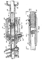
- a steering gear A (Fig. 2) which includes a force transmitting member 15 which moves linearly in opposite directions to cause pivoting of the dirigible wheels 16, 17 of the vehicle about a vertical axis.
- the steering gear A of the present invention is embodied in a system illustrated in Fig. 1.
- the system of Fig. 1 responds to rotation of a hand or steering wheel 10.
- a driver input. torque is applied to a torsion bar 11 located in a steering column in series with the steering wheel 10.
- the electronic torsion bar deflection sensor 12 applies a signal to an electronic control unit 13 (Fig. 1) which signal indicates the direction and amount of twist, i.e., deflection of the torsion bar 11.
- the direction and amount of deflection of the torsion bar 11 are related to the direction of steering wheel rotation and the torque applied to the steering column.
- Other inputs may also be communicated to the electronic control unit 13. These other inputs, for example, may be the speed of the vehicle.
- the electronic control unit 13 After receiving all of the desired inputs, the electronic control unit 13 provides an output control current to an electric motor 14 to operate same in a direction of rotation and at a speed and torque which is related to the applied current.
- the electric motor 14 will then apply a steering assist force to the translatable member 15.
- a manual drive is provided between the driver's input and the member 15 so that manual steering occurs.
- the member 15 When the member 15 (Fig. 2) moves, it effects a pivoting movement of the dirigible wheels 16, 17 of the vehicle.
- the member 15 moves linearly in opposite directions.
- the member 15 is moved linearly in opposite directions, either by a manual force applied thereto due to rotation of the handwheel 10 or by a combination of the manual force and the force applied thereto by the electric motor 14.
- the member 15 has a screw portion 20 (Fig. 3) having a screw thread or worm 20a thereon.
- the member 15 also has a portion 21 which has rack teeth 22 thereon.
- the rack teeth 22 extend transverse to the direction of movement of the member 15.
- the portion 21 is aligned with the portion 20 and attached thereto for simultaneous movement.
- a steering column member 41 (see Fig. 2) is rotated.
- the steering column member 41 is connected to an upper coupling member 40 which is also rotated.
- the upper coupling member 40 is mechanically connected to the steering column member 41 through a Cardon joint 42.
- the coupling member 40 in part encircles a lower coupling member 50 (see Fig. 6) which is attached by a Cardon joint 52 (Fig. 2) to a steering gear input shaft 53.
- the steering gear input shaft 53 has a pinion gear 54 drivingly connected thereto (see Fig. 3).
- the pinion gear 54 is a helical pinion which meshes with the rack teeth 22.
- the torsion bar 11 is interposed between the coupling parts 40, 50 (see Fig. 6).
- the coupling part 40 has a tubular portion 51 which receives a tubular portion 52 of the coupling part 50.
- the outer surface of the coupling part 50.and the inner surface of the coupling part 40 engage.
- One end of the torsion bar 11 is pinned to the upper coupling part 40 and the other end is pinned to the lower coupling part 50.
- the torsion bar 11 is located coaxial with the coupling parts 40, 50.
- the torsion bar deflection sensor 12, shown in Fig. 7, includes a Hall effect device 60 and a pair of magnets 61, 62.
- the pair of magnets 61, 62 are carried on a portion 64 of the coupling part 50.
- the portion 64 projects between opposite leg portions 40a, 40b of the coupling part 40.
- the Hall effect device 60 is carried on a plate 67 attached to the coupling part 40.
- the magnet 61 has its north pole facing the Hall effect device 60.
- the magnet 62 has its south pole facing the Hall effect device 60.
- the signal indicates the amount of twisting of the torsion bar 11, i.e., the amount of angular movement of one end of the torsion bar relative to the other end, and the direction of rotation of the torsion bar.
- the electronic torsion bar sensor 12 disclosed herein is not my invention, and is disclosed to comply with the "best mode" requirement of 35 USC 112.
- the electric motor 14 (Fig. 3) is a reversible permanent magnet electric motor.
- the motor 14 is mounted coaxially of the screw portion 20 of the member 15.
- the motor 14 includes a housing member 70 which is fixedly connected with the frame of the vehicle and carries a plurality of permanent magnets 71.
- the permanent magnets 71 surround a rotatable motor armature 73.
- the armature 73 is of a conventional construction.
- the armature 73 is made up of a plurality of plastic laminations having windings wound therearound.
- the armature 73 encircles a ball nut 75.
- the ball nut 75 is a tubular member which extends coaxially of the screw portion 20 of the member 15.
- the outer diameter of the ball nut 75 is knurled at 77, shown in Fig. 5.
- the knurling 77 provides a friction drive between the inner diameter of the armature 73 and the ball nut 75.
- the ball nut 75 is rotated.
- the member 15 is driven axially because of the cooperation of the plurality of balls 78 (Fig. 4) associated with the ball nut 75 and the screw portion 20 of the member 15.
- the balls 78 are located in a recirculating channel 79 in the ball nut 75, in a portion of the screw thread 20a on the member 15 and in a corresponding screw thread on the inner diameter of the ball nut 75.
- the rotation of the ball nut 75 effects linear movement of the member 15.
- the ball nut 75 is supported at its opposite ends in bearings 90, 91 (Fig. 3).
- the bearings 90, 91 support the ball nut 75 for rotation relative to the housing 70 of the electric motor 14.
- the bearing 90 is located between an end portion 92 of the ball nut 75 and an end cap 93 at the left end of the motor 14, as viewed in Figure 3.
- the bearing 91 is located between a projecting portion 101 of the ball nut 75 and an end cap 103 on the right end of the motor 14, as viewed in Figure 3.
- the bearings 90 and 91 support the ball nut for rotation and also restrain the ball nut 75 from axial movement relative thereto as is clear from the drawings.
- the various parts of the motor 14 are secured together by suitable fasteners 105 which extend through the end cap 103, and into the end cap 93.
- the screw fasteners hold the entire motor 14 axially together.
- a suitable housing member, generally designated.107, is welded to the end cap 93 and defines a chamber for the pinion 54.
- the housing 107 at its leftwardmost end, as viewed in Figure 3, is suitably attached to a boot 109.
- the boot 109 extends along the member 15 and is attached thereto at its outer end.
- the boot 109 cooperates with a seal 109a to maintain lubricant for the gears, bearings, etc. in the housing 102 and prevent dust, dirt and any other foreign matter from entering the housing and affecting performance of the pinion 54, etc.
- the end cap 103 also has a protecting portion 110 welded thereto.
- the portion 110 projects along member 15 to the right, as shown in Figure 3, and terminates at its outer end in a portion having a boot 112 attached thereto.
- the boot 112 cooperates with a seal 112a to block dirt, dust and other foreign matter from contact with the electric motor 14.
- the brushes 115 comprise a brush 116 which runs in contact with a commutator bar 117 associated with the armature 73.
- the brush 116 is encapsulated in a plastic cylinder 118 which has a plastic head 119 thereon.
- a metal sleeve 120 encircles the plastic cylinder 118 and is threaded into the housing 70 of the motor.
- An electrical lead is suitably attached to the brush 116.
- the present invention may operate in a variety of different modes. For example, if the vehicle wheels 16, 17 are on ice and may be turned by an extremely small force, the steering of the vehicle may occur manually and the electric motor 14 not be energized. Under such conditions, when the steering wheel 10 is turned, the torsion bar il may be able to transmit enough torque to the pinion 54 to effect steering without substantial deflection. If this occurs, steering occurs in response to the pinion 54 rotating and transmitting manual force to the member 15 due to engagement of the teeth of the rack 22 with the teeth of the pinion 54. Under such condition the motor armature 73 will rotate but no detrimental affect results.
- the wheels of the vehicle 16 are on a surface where there is a substantial resistance to turning the wheels, turning of the hand wheel 10 will deflect the torsion bar 11.
- the deflection of the torsion bar 11 is limited by surfaces 130 or 131 (see Fig. 7) on the upper coupling part 40 engaging a facing surface 132 or 133 on the lower coupling part 50. When a pair of these surfaces engage, the amount of twisting that can occur in the torsion bar 11-is limited. Also, at maximum deflection of the torsion bar ll, there is a direct mechanical drive from the steering wheel 10 to the pinion 54.
- the electronic torsion bar sensor 12 is energized to provide a maximum electrical signal to the electronic control unit 13.
- the electric motor 14 is therefore energized to a maximum torque.
- the ball nut 75 rotates and a force is applied through the balls 78 to effect movement of the member 15.
- This force is applied directly to the member 15 independently of the pinion, i.e., the force is not transmitted through the pinion.
- both the electric motor 14 and pinion 54 simultaneously apply a force to the member 15 to effect movement of the member 15 to cause turning of the wheels 16, 17 of the vehicle.
- the motor 14 will be energized due to the fact that the electronic torsion bar sensor 12 will sense the twisting of the torsion bar. As a result, the motor 14 will be energized and a force will be applied by the motor 14 to the screw portion 20 of the member 15. Thus, the manual force and the assisting force of the motor 14 will be applied to the member 15.
- the operator may turn the steering wheel 10 through a given angular movement and then either hold the steering wheel or may release the steering wheel. In either situation, turning of the wheels 16, 17 by the steering gear will stop and the torsion bar deflection sensor will be de-energized. If the operator releases the steering wheel 10 as is known, the reaction of the wheels 16, 17 on the road will tend to straighten the wheels. The torsion-bar 11 will due to internal resiliency, return to an undeflected stated, and the magnets 61, 62 will return to a neutral position relative to the Hall effect device 60.
- the motor 14 will cause movement of the member 15, rack 22, and rotate the pinion 54 to cause an untwisting of the torsion bar and a return of the magnets 61, 62 to a neutral position relative to the Hall effect device 60. The motor 14 will then be de-energized.
- the parts are in the positions shown in Fig. 3.
- the ball nut 75 is located so that the balls 78 are associated with the center part of the screw portion 20 of the member 15. Specifically, the center (indicated by the line X in Fig. 3) is located equal distances from the opposite end of the screw portion 20. Also, the pinion 54 is located centrally of the rack portion 21.
- the present invention provides a very compact, low cost electrical power rack and pinion steering gear.
- the steering gear is constructed so that when torque is applied to the hand wheel in excess of a predetermined amount, i.e., sufficient to cause a twisting of the torsion bar 11, the electric motor 14 is energized.
- a predetermined amount i.e., sufficient to cause a twisting of the torsion bar 11
- the electric motor 14 is energized.
- manual failsafe steering is provided in the event of a failure in the electrical assist.
- FIG. 8 A modified embodiment of the present invention is illustrated in Fig. 8.
- the embodiment shown in Fig. 8 is similar to the embodiment described above, but in addition includes a clutch mechanism 150 interposed between the armature 151 and the ball nut 152.
- the clutch mechanism 150 provides for disengagement of the armature. 151 from the ball nut 163 when the electric motor is not energized.
- a member 160 moves in opposite directions to effect steering of the vehicle.
- the member 160 is similar to the member 15 in the embodiment of Fig. 2.
- the member 160 includes a screw portion 161 and a rack portion 162.
- the rack portion 162 is adapted to cooperate with a pinion (not shown) and to effect movement of the member 160 in opposite directions in response to rotation of the pinion.
- the screw portion 161 cooperates with the ball nut 163.
- the member 160 moves linearly due to the cooperation of the ball nut 163 and balls 164 which run in a complimentary screw thread in the internal diameter of the ball nut 163 and in the outer diameter of the screw portion 161 of the member 160.
- the armature 151 is fixedly attached to a sleeve member 170.
- the sleeve member 170 is slidably and rotationally supported on the outer diameter 1 71 ot the ball nut 163.
- the armature 151 is adjacent a plurality of permanent magnets 175.
- the magnets 175 encircle the armature 151.
- the armature 151 is axially offset in the magnetic field provided by magnets 175. Current is communicated to and from the armature 151 through a plurality of brushes, designated 177 and 178, which run in contact with a combar 180 associated with the armature 151.
- the clutch 150 comprises a pair of flanges 181, 182.
- Flange 182 is fixed on the sleeve 170.
- Flange 181 is fixed to the ball nut 163.
- the flange 182 carries friction material 183.
- Axial movement of the sleeve 170 causes the friction material 183 to engage flange 181.
- the rotational movement of the armature 151 is transmitted to the ball nut 163 to effect rotation thereof.
- the arrangement of parts is such that the armature 151 never becomes totally centralized between the permanent magnets. Thus, there is a continuous biasing force causing a pressure engagement between the clutch faces while current is flowing through the armature.
- Fig. 8 is similar to the embodiment of Fig. 3 except that in the embodiment of Fig. 8 there is a clutch disposed between the armature and the member 160 to eliminate any necessity of the armature 151 rotating when manual steering occurs.
Landscapes
- Engineering & Computer Science (AREA)
- Chemical & Material Sciences (AREA)
- Combustion & Propulsion (AREA)
- Transportation (AREA)
- Mechanical Engineering (AREA)
- Power Engineering (AREA)
- Power Steering Mechanism (AREA)
- Transmission Devices (AREA)
Applications Claiming Priority (2)
| Application Number | Priority Date | Filing Date | Title |
|---|---|---|---|
| US06/405,705 US4415054A (en) | 1982-08-05 | 1982-08-05 | Steering gear |
| US405705 | 1982-08-05 |
Publications (3)
| Publication Number | Publication Date |
|---|---|
| EP0101579A2 true EP0101579A2 (de) | 1984-02-29 |
| EP0101579A3 EP0101579A3 (en) | 1984-07-25 |
| EP0101579B1 EP0101579B1 (de) | 1989-04-26 |
Family
ID=23604865
Family Applications (1)
| Application Number | Title | Priority Date | Filing Date |
|---|---|---|---|
| EP83107499A Expired EP0101579B1 (de) | 1982-08-05 | 1983-07-29 | Lenkung |
Country Status (10)
| Country | Link |
|---|---|
| US (2) | US4415054A (de) |
| EP (1) | EP0101579B1 (de) |
| JP (1) | JPS5950864A (de) |
| KR (1) | KR890000831B1 (de) |
| AU (1) | AU564833B2 (de) |
| BR (1) | BR8304176A (de) |
| CA (1) | CA1190864A (de) |
| DE (1) | DE3379723D1 (de) |
| ES (1) | ES8406049A1 (de) |
| MX (1) | MX158041A (de) |
Cited By (15)
| Publication number | Priority date | Publication date | Assignee | Title |
|---|---|---|---|---|
| GB2146300A (en) * | 1983-07-22 | 1985-04-17 | Nippon Seiko Kk | Power assist steering gear assembly |
| EP0124418A3 (en) * | 1983-04-28 | 1985-06-26 | Bendiberica S.A. | Rack and pimion electrical servo steering mechanism for an automative vehicle |
| FR2570666A1 (fr) * | 1984-09-27 | 1986-03-28 | Honda Motor Co Ltd | Systeme de direction assistee electriquement pour automobiles |
| GB2165505A (en) * | 1984-10-11 | 1986-04-16 | Honda Motor Co Ltd | Motor-driven power steering unit |
| FR2576266A1 (fr) * | 1985-01-22 | 1986-07-25 | Honda Motor Co Ltd | Dispositif de servodirection electrique pour vehicules |
| EP0190678A1 (de) * | 1985-02-02 | 1986-08-13 | Hitachi, Ltd. | Elektromotorisches Servolenkverfahren und System |
| EP0174137A3 (de) * | 1984-08-30 | 1987-07-15 | Eaton Corporation | Sicherheitsmechanismus für ein elektrisches Servolenkungssystem |
| GB2187692A (en) * | 1986-03-12 | 1987-09-16 | Honda Motor Co Ltd | Motor-driven power steering device |
| FR2596722A1 (fr) * | 1986-02-21 | 1987-10-09 | Roltra Spa | Direction assistee pour vehicules automobiles |
| FR2600030A1 (fr) * | 1986-04-23 | 1987-12-18 | Honda Motor Co Ltd | Systeme de direction a quatre roues directrices assistee par moteur electrique |
| GB2198098A (en) * | 1986-10-20 | 1988-06-08 | Honda Motor Co Ltd | Rear wheel steering device for vehicle with four steerable wheels |
| FR2608120A1 (fr) * | 1986-12-10 | 1988-06-17 | Renault | Mecanisme de direction assistee a commande electrique pour vehicules automobiles |
| WO2001040046A1 (de) * | 1999-12-01 | 2001-06-07 | Krupp Presta Ag | Rohrförmige, elektrisch unterstützte linkhilfe mit hohem wirkungsgrad |
| DE10118466A1 (de) * | 2001-04-11 | 2002-10-17 | Siemens Ag | Lenkeinrichtung |
| US6960145B2 (en) | 2002-08-30 | 2005-11-01 | Trw, Inc. | Belt tensioner for electric power steering unit |
Families Citing this family (118)
| Publication number | Priority date | Publication date | Assignee | Title |
|---|---|---|---|---|
| JPS5963264A (ja) * | 1982-10-05 | 1984-04-10 | Aisin Seiki Co Ltd | 電動パワ−ステアリング装置 |
| MX156827A (es) * | 1983-05-05 | 1988-10-03 | Allied Corp | Mejoras a mecanismo de direccion asistido por energia electrica para un vehiculo automotriz |
| JPS59172072U (ja) * | 1983-05-06 | 1984-11-17 | トヨタ自動車株式会社 | 電気式倍力操舵装置 |
| JPS6025854A (ja) * | 1983-07-22 | 1985-02-08 | Nippon Seiko Kk | 電気式動力舵取装置 |
| JPS6025853A (ja) * | 1983-07-22 | 1985-02-08 | Nippon Seiko Kk | 電気式動力舵取装置 |
| JPS6035664A (ja) * | 1983-08-08 | 1985-02-23 | Aisin Seiki Co Ltd | 電動パワ−ステアリング装置 |
| FR2556681B1 (fr) * | 1983-12-16 | 1988-04-08 | Citroen Sa | Direction de vehicule automobile a commande assistee par un moteur electrique |
| JPS60122274U (ja) * | 1984-01-25 | 1985-08-17 | 日本精工株式会社 | 電気式動力舵取装置 |
| JPS60144572U (ja) * | 1984-03-07 | 1985-09-25 | 日本精工株式会社 | 電気式動力舵取装置 |
| US4550597A (en) * | 1984-04-04 | 1985-11-05 | Trw Inc. | Method and apparatus for sensing relative movement between members |
| GB2161030B (en) * | 1984-06-22 | 1988-05-05 | Honda Motor Co Ltd | Apparatus for interconnection of a multi-channel communication network |
| US4566338A (en) * | 1984-07-20 | 1986-01-28 | Trw Inc. | Noncontact torque sensor |
| JPS6130462A (ja) * | 1984-07-20 | 1986-02-12 | Honda Motor Co Ltd | 電磁型倍力装置 |
| JPH0331665Y2 (de) * | 1984-09-05 | 1991-07-04 | ||
| JPS6181866A (ja) * | 1984-09-12 | 1986-04-25 | Honda Motor Co Ltd | 電動式パワ−ステアリング装置 |
| JPS6189170A (ja) * | 1984-10-08 | 1986-05-07 | Fuji Heavy Ind Ltd | 電動式パワ−ステアリング装置 |
| JPS61105272A (ja) * | 1984-10-26 | 1986-05-23 | Honda Motor Co Ltd | 電磁型倍力装置 |
| JPS61110669A (ja) * | 1984-11-02 | 1986-05-28 | Honda Motor Co Ltd | 電磁型倍力装置 |
| JPH0729610B2 (ja) * | 1984-11-02 | 1995-04-05 | 本田技研工業株式会社 | 電磁型倍力装置 |
| US4598787A (en) * | 1984-11-30 | 1986-07-08 | Trw Inc. | Control apparatus for power assist steering system |
| JPH0696385B2 (ja) * | 1984-12-10 | 1994-11-30 | 日本精工株式会社 | 電気式動力舵取装置 |
| JPS61139560A (ja) * | 1984-12-10 | 1986-06-26 | Nippon Seiko Kk | 電気式動力舵取装置 |
| US4681182A (en) * | 1985-04-11 | 1987-07-21 | Jidosha Kiki Co., Ltd. | Electric power steering apparatus |
| AU590587B2 (en) * | 1985-07-12 | 1989-11-09 | Siemens Aktiengesellschaft | Electric power assisted steering mechanism |
| JPS6234850A (ja) * | 1985-08-06 | 1987-02-14 | Honda Motor Co Ltd | 電動式パワ−ステアリング装置 |
| US4683971A (en) * | 1985-09-13 | 1987-08-04 | General Motors Corporation | Concentric motor electric power steering for rack and pinion gear with center take-off |
| US4653602A (en) * | 1985-10-17 | 1987-03-31 | General Motors Corporation | Electric motor driven rack and pinion steering gear with take-off from axially slidable nut |
| US4800974A (en) * | 1985-10-23 | 1989-01-31 | Trw Inc. | Electric steering gear |
| US4660671A (en) * | 1985-10-23 | 1987-04-28 | Trw Inc. | Electric steering gear |
| JPH0649489Y2 (ja) * | 1986-02-06 | 1994-12-14 | 本田技研工業株式会社 | 電動式パワ−ステアリング装置 |
| GB8603084D0 (en) * | 1986-02-07 | 1986-03-12 | Trw Cam Gears Ltd | Road vehicle power assisted steering system |
| GB2186245B (en) * | 1986-02-12 | 1989-06-07 | Honda Motor Co Ltd | Steering gear box mounts |
| IT207930Z2 (it) * | 1986-02-21 | 1988-02-22 | Roltra Spa | Sistema a frizione servoassistito |
| JPH0522465Y2 (de) * | 1986-07-16 | 1993-06-08 | ||
| US4757869A (en) * | 1986-03-19 | 1988-07-19 | Mitsubishi Denki Kabushiki Kaisha | Motor-driven power steering system for a vehicle |
| US4762194A (en) * | 1986-03-26 | 1988-08-09 | Mitsubishi Denki Kabushiki Kaisha | Motor-driven power steering system for a vehicle |
| JPH0723104B2 (ja) * | 1986-04-22 | 1995-03-15 | 三菱電機株式会社 | モ−タ駆動式パワ−ステアリング制御装置 |
| KR900005710B1 (ko) * | 1986-04-29 | 1990-08-06 | 미쓰비시전기 주식회사 | 모터구동식 동력조향 제어장치 |
| KR910000396B1 (ko) * | 1986-04-29 | 1991-01-25 | 미쓰비시전기 주식회사 | 모터구동식 동력조항 제어장치 |
| US4773497A (en) * | 1986-05-08 | 1988-09-27 | Trw Inc. | Floating ball-nut for an electric assist steering system |
| US4666014A (en) * | 1986-05-08 | 1987-05-19 | Trw Inc. | Floating ball-nut for an electric assist steering system |
| US4694925A (en) * | 1986-05-30 | 1987-09-22 | Trw Inc. | Steering apparatus |
| JPS6387371A (ja) * | 1986-09-29 | 1988-04-18 | Honda Motor Co Ltd | 前後輪操舵車両の電動機式動力舵取装置 |
| JPH05472Y2 (de) * | 1986-10-09 | 1993-01-07 | ||
| JPS6376580U (de) * | 1986-11-10 | 1988-05-21 | ||
| US4811813A (en) * | 1987-02-17 | 1989-03-14 | Trw Inc. | Center take-off electric rack and pinion steering gear |
| US4751978A (en) * | 1987-03-16 | 1988-06-21 | Trw Inc. | Electric assist steering system with alternator power source |
| US4794210A (en) * | 1987-07-30 | 1988-12-27 | Trw Inc. | Reversing switch assembly for an electric assist steering system |
| US4918921A (en) | 1987-10-22 | 1990-04-24 | Automotive Products Plc | Coaxial push rod and hollow screw ball nut drive for master cylinder |
| US4887682A (en) | 1988-01-06 | 1989-12-19 | Trw Inc. | Method and apparatus for nullifying electrical offsets in a torsion sensor |
| US4940107A (en) | 1988-09-23 | 1990-07-10 | Trw Inc. | Method and apparatus for controlling a power assist steering system |
| FR2657317B1 (fr) * | 1990-01-22 | 1992-05-07 | Renault | Dispositif de braquage de roues arriere pour vehicule a quatre roues directrices. |
| US5248939A (en) * | 1990-02-22 | 1993-09-28 | The Torrington Company | Apparatus for sensing the direction and speed of a steering wheel shaft using hall effect sensors in a detachable sensor mounting |
| US5051693A (en) * | 1990-09-07 | 1991-09-24 | The Torrington Company | Bearing seat encoder mount for rotational parameter sensor apparatus |
| US5198981A (en) * | 1990-10-09 | 1993-03-30 | General Motors Corporation | Closed-loop torque control for electric power steering |
| ES2068051B1 (es) * | 1991-06-20 | 1996-08-01 | De Cepeda Juan Gutierrez | Sistema de direccion de desmultiplicacion variable en funcion de la velocidad. |
| AU2049492A (en) * | 1991-07-24 | 1993-01-28 | Koyo Seiko Co., Ltd. | Steering device and speed reduction device |
| US5257828A (en) * | 1992-06-03 | 1993-11-02 | Trw Inc. | Method and apparatus for controlling damping in an electric assist steering system for vehicle yaw rate control |
| DE4407729C2 (de) * | 1993-03-08 | 1999-03-11 | Honda Motor Co Ltd | Elektrisch betriebene Servolenkungseinrichtung |
| US5555951A (en) * | 1993-09-24 | 1996-09-17 | Honda Giken Kogyo Kabushiki Kaisha | Electrically operated power steering apparatus with improved housing assembly |
| JP2904329B2 (ja) * | 1993-12-17 | 1999-06-14 | 本田技研工業株式会社 | ステアリング装置 |
| US5568389A (en) * | 1994-03-11 | 1996-10-22 | Trw Inc. | Method and apparatus for controlling an electric assist steering system |
| US5473231A (en) * | 1994-05-11 | 1995-12-05 | Trw Inc. | Method and apparatus for controlling an electric assist steering system using an adaptive torque filter |
| DE69520981T2 (de) * | 1994-05-20 | 2002-04-04 | Trw Inc., Lyndhurst | Verfahren und Vorrichtung zur Regelung eines elektrischen Hilfskraftlenksystems mit einem adaptiven Übergangsfilter für das Drehmoment |
| US5527053A (en) * | 1994-08-29 | 1996-06-18 | Howard; Durrell U. | Detent centering compensator for vehicle steering systems |
| JP3059059B2 (ja) * | 1994-09-27 | 2000-07-04 | 本田技研工業株式会社 | 動力操舵装置用電動機 |
| DE4438930C1 (de) * | 1994-10-31 | 1995-10-26 | Daimler Benz Ag | Zahnstangenlenkung bzw. -steuerung mit Servomotor |
| US5623409A (en) * | 1994-10-31 | 1997-04-22 | Trw Inc. | Method and apparatus for non-linear damping of an electric assist steering system for vehicle yaw rate control |
| US5475289A (en) | 1994-11-04 | 1995-12-12 | Trw Inc. | Method and apparatus for controlling an electric assist steering system using two-dimensional interpolation for current commands |
| US5786754A (en) | 1995-12-13 | 1998-07-28 | Trw Inc. | Method and apparatus for electronically cancelling a vehicle direction signal in an electric assist steering system |
| JP4095124B2 (ja) † | 1996-06-19 | 2008-06-04 | 株式会社ジェイテクト | 電動パワーステアリング装置 |
| TW376426B (en) | 1996-10-16 | 1999-12-11 | Honda Motor Co Ltd | Engine for vehicle |
| US6026924A (en) * | 1997-02-10 | 2000-02-22 | Trw Inc. | Steering gear |
| US5992556A (en) | 1997-04-15 | 1999-11-30 | Trw Inc. | Method and apparatus for damping control of an electric assist steering system with vehicle speed signal loss feature |
| US5921344A (en) * | 1997-06-03 | 1999-07-13 | Trw Inc. | Electric steering system |
| JPH1111333A (ja) | 1997-06-25 | 1999-01-19 | Honda Motor Co Ltd | 電動パワーステアリング装置 |
| JP2966818B2 (ja) | 1997-07-01 | 1999-10-25 | 本田技研工業株式会社 | 電動パワーステアリング装置 |
| JPH1134891A (ja) | 1997-07-24 | 1999-02-09 | Mitsuba Corp | 電気式動力操舵装置 |
| US5975234A (en) * | 1997-12-03 | 1999-11-02 | Trw Inc. | Electric steering system with plastic motor tube |
| US6107767A (en) * | 1998-03-20 | 2000-08-22 | Trw Inc. | Electric assist steering system having an improved motor current controller with notch filter |
| US6046560A (en) | 1998-03-20 | 2000-04-04 | Trw Inc. | Electric assist steering system having an improved motor current controller with gain scheduler |
| US6068078A (en) * | 1998-06-16 | 2000-05-30 | Trw Inc. | Electric steering system |
| US6155376A (en) * | 1998-12-28 | 2000-12-05 | Trw Inc. | Electric power steering assembly |
| EP1026067B1 (de) * | 1999-02-04 | 2003-12-17 | Ntn Corporation | Elektrisch angetriebene Lenkeinrichtung |
| US6295879B1 (en) | 1999-03-08 | 2001-10-02 | Trw Inc. | Torque sensing apparatus for an electric assist steering system |
| DE19931850A1 (de) * | 1999-07-09 | 2001-01-11 | Mercedes Benz Lenkungen Gmbh | Kraftfahrzeugservolenkung mit elektrischem Servomotor und Planetenwälzgetriebespindeltrieb |
| DE29915559U1 (de) * | 1999-09-03 | 2000-01-13 | TRW Fahrwerksysteme GmbH & Co KG, 40547 Düsseldorf | Lenksystem für ein Fahrzeug |
| EP1110845A1 (de) * | 1999-12-21 | 2001-06-27 | Ford Global Technologies, Inc. | Kraftfahrzeuglenksystem |
| US6360841B1 (en) | 2000-02-29 | 2002-03-26 | Trw Inc. | Power steering mechanism with magnetoelastic torsion bar |
| JP2001275325A (ja) * | 2000-03-27 | 2001-10-05 | Honda Motor Co Ltd | 電動パワーステアリング装置 |
| NL1014911C2 (nl) | 2000-04-11 | 2001-10-12 | Skf Eng & Res Centre Bv | Elektrisch schroefactuatorsysteem. |
| US6378646B1 (en) | 2000-08-22 | 2002-04-30 | Trw Inc. | Pivotal ballnut connection for a power assisted steering system |
| DE10050909B4 (de) * | 2000-10-13 | 2011-06-16 | Thyssenkrupp Presta Steertec Gmbh | Kraftfahrzeugservolenkung mit elektrischem Servomotor und Rädergetriebe |
| US6713921B2 (en) * | 2001-05-08 | 2004-03-30 | Delphi Technologies, Inc. | Permanent magnet structure for brushless motor and power assist actuator using the same |
| US7591342B2 (en) * | 2001-08-01 | 2009-09-22 | Delphi Technologies, Inc. | Apparatus and method for steering a vehicle |
| US6488115B1 (en) * | 2001-08-01 | 2002-12-03 | Delphi Technologies, Inc. | Apparatus and method for steering a vehicle |
| US7293626B2 (en) * | 2001-08-01 | 2007-11-13 | Delphi Technologies, Inc. | Apparatus and method for steering a vehicle |
| US6701792B2 (en) | 2001-08-27 | 2004-03-09 | Visteon Global Technologies, Inc. | Torque sensing apparatus for measuring relative torque between two shafts |
| EP1702831B1 (de) | 2001-11-30 | 2009-01-07 | TRW Automotive U.S. LLC | Verfahren und Vorrichtung zum Regeln von Lenkgefühl mit Diagnosen |
| FR2832972B1 (fr) * | 2001-12-05 | 2004-03-05 | Soc Mecanique Irigny | Direction a cremaillere de vehicule automobile |
| JP2003252231A (ja) * | 2002-02-28 | 2003-09-10 | Aisin Seiki Co Ltd | 車両の後輪操舵装置 |
| KR100816418B1 (ko) * | 2002-03-14 | 2008-03-27 | 주식회사 만도 | 랙 구동식 전동 파워스티어링 시스템 |
| US6889792B1 (en) | 2002-08-01 | 2005-05-10 | Trw Inc. | Electrically assisted power steering system with anti-theft capability |
| JP4085878B2 (ja) * | 2003-04-25 | 2008-05-14 | 株式会社ジェイテクト | 電動パワーステアリング装置 |
| US20050155809A1 (en) * | 2004-01-20 | 2005-07-21 | Krzesicki Richard M. | Mechanical clutch coupling back-up for electric steering system |
| GB0401965D0 (en) * | 2004-01-30 | 2004-03-03 | Trw Lucasvarity Electric Steer | Method and apparatus for controlling an electric assist motor using a modified blending filter |
| JP2005263149A (ja) * | 2004-03-22 | 2005-09-29 | Nsk Ltd | 電動式パワーステアリング装置 |
| WO2006099483A1 (en) | 2005-03-15 | 2006-09-21 | Trw Automotive U.S. Llc | Method and apparatus for controlling an electric assist steering system using an adaptive blending torque filter and road feel filter |
| DE102005017883A1 (de) * | 2005-04-19 | 2006-10-26 | Zf Lenksysteme Gmbh | Vorrichtung zur drehbaren Lagerung |
| WO2007005533A2 (en) * | 2005-06-30 | 2007-01-11 | Globe Motors, Inc. | Steering system torque sensor |
| US7780180B2 (en) * | 2007-08-27 | 2010-08-24 | Hoepner John M | Knee walker |
| DE102008059745A1 (de) * | 2008-12-01 | 2010-06-02 | Thyssenkrupp Presta Ag | Elektromechanische Servolenkung mit Kugelgewindetrieb |
| US8727067B2 (en) * | 2011-06-30 | 2014-05-20 | Ford Global Technologies, Llc | Method for supplying power to an electrically assisted steering system |
| JP6295469B2 (ja) * | 2014-02-27 | 2018-03-20 | 日立オートモティブシステムズ株式会社 | パワーステアリング装置およびパワーステアリング装置の製造方法 |
| EA030874B1 (ru) * | 2015-05-08 | 2018-10-31 | Акционерное общество "Диаконт" | Линейный электромеханический привод |
| JP6705653B2 (ja) * | 2016-01-19 | 2020-06-03 | トヨタ自動車株式会社 | ステアリング装置 |
| DE102017211859B4 (de) * | 2017-07-11 | 2021-04-22 | Volkswagen Aktiengesellschaft | Multifunktionale Lenksäule, Kraftfahrzeug und Verfahren zum Betreiben eines Kraftfahrzeugs |
| US20240391518A1 (en) * | 2023-05-23 | 2024-11-28 | Ford Global Technologies, Llc | Steering gears with electric steering assist systems and related methods |
Family Cites Families (23)
| Publication number | Priority date | Publication date | Assignee | Title |
|---|---|---|---|---|
| US1231885A (en) * | 1915-09-16 | 1917-07-03 | John O Heinze Company | Electric steering mechanism. |
| US1711662A (en) * | 1926-09-01 | 1929-05-07 | Harold C Suekert | Power steering mechanism |
| US2446393A (en) * | 1945-06-14 | 1948-08-03 | Eaton Mfg Co | Screw-threaded mechanical movement |
| GB645000A (en) | 1946-04-13 | 1950-10-25 | Letourneau Inc | Road grader |
| US2670449A (en) * | 1952-10-04 | 1954-02-23 | Thomas J Mcmahon | Electric motor |
| DE964565C (de) * | 1953-08-31 | 1957-05-23 | Lear Inc | Kraftverstaerkersystem mittels Elektromotors fuer einen Kraftfahrzeug-Steuermechanismus |
| BE628339A (de) * | 1962-02-14 | |||
| GB972729A (en) * | 1962-05-11 | 1964-10-14 | Hydrosteer Ltd | Improvements in vehicular steering mechanism |
| US3512426A (en) * | 1969-06-25 | 1970-05-19 | Gustav H Dabringhaus | Internal ball recirculating mechanism for recirculating ball screw and nut assembly |
| US3716110A (en) * | 1970-07-22 | 1973-02-13 | A Fonda | Steering and directing mechanism |
| DE2118813A1 (de) * | 1971-04-19 | 1972-11-02 | Zahnradfabrik Friedrichshafen Ag, 7990 Friedrichshafen | Lenkgetriebe |
| US3983953A (en) * | 1971-07-28 | 1976-10-05 | Gemmer-France | Servo mechanism |
| GB1410956A (en) | 1972-11-28 | 1975-10-22 | Fonda Ag | Power directing system |
| GB1424937A (en) * | 1973-03-05 | 1976-02-11 | Nissan Motor | Automotive steering system process for the production of bis-halogen carbonyl anilines |
| FR2263141A1 (en) * | 1974-03-04 | 1975-10-03 | Gemmer France | Electric power assisted vehicle steering system - has starter motor also used for auxiliary power steering source |
| US4019616A (en) * | 1976-06-24 | 1977-04-26 | International Business Machines Corporation | Linear motion drive apparatus for a printer carriage |
| GB1548010A (en) * | 1976-08-06 | 1979-07-04 | Cam Gears Ltd | Steering gears |
| GB1590629A (en) * | 1976-09-23 | 1981-06-03 | Cam Gears Ltd | Powerassisted gear system |
| JPS5544013A (en) * | 1978-09-18 | 1980-03-28 | Kayaba Ind Co Ltd | Power steering apparatus |
| JPS5544058A (en) * | 1978-09-22 | 1980-03-28 | Kayaba Ind Co Ltd | Power steering |
| JPS5547963A (en) * | 1978-09-27 | 1980-04-05 | Asmo Co Ltd | Electric power steering apparatus |
| JPS5747251A (en) * | 1980-09-03 | 1982-03-18 | Toyota Motor Corp | Electric power steering |
| JPS57120164U (de) * | 1981-01-22 | 1982-07-26 |
-
1982
- 1982-08-05 US US06/405,705 patent/US4415054A/en not_active Ceased
-
1983
- 1983-07-29 DE DE8383107499T patent/DE3379723D1/de not_active Expired
- 1983-07-29 EP EP83107499A patent/EP0101579B1/de not_active Expired
- 1983-08-01 AU AU17482/83A patent/AU564833B2/en not_active Expired
- 1983-08-03 MX MX198280A patent/MX158041A/es unknown
- 1983-08-04 BR BR8304176A patent/BR8304176A/pt not_active IP Right Cessation
- 1983-08-04 ES ES524753A patent/ES8406049A1/es not_active Expired
- 1983-08-04 CA CA000433928A patent/CA1190864A/en not_active Expired
- 1983-08-05 JP JP58142659A patent/JPS5950864A/ja active Pending
- 1983-08-05 KR KR1019830003666A patent/KR890000831B1/ko not_active Expired
-
1984
- 1984-11-06 US US06/668,658 patent/USRE32222E/en not_active Expired - Lifetime
Cited By (21)
| Publication number | Priority date | Publication date | Assignee | Title |
|---|---|---|---|---|
| EP0124418A3 (en) * | 1983-04-28 | 1985-06-26 | Bendiberica S.A. | Rack and pimion electrical servo steering mechanism for an automative vehicle |
| GB2146300A (en) * | 1983-07-22 | 1985-04-17 | Nippon Seiko Kk | Power assist steering gear assembly |
| EP0133003B1 (de) * | 1983-07-22 | 1991-03-13 | Nippon Seiko Kabushiki Kaisha | Zusammenbau des Getriebes einer Servolenkung |
| EP0174137A3 (de) * | 1984-08-30 | 1987-07-15 | Eaton Corporation | Sicherheitsmechanismus für ein elektrisches Servolenkungssystem |
| FR2570666A1 (fr) * | 1984-09-27 | 1986-03-28 | Honda Motor Co Ltd | Systeme de direction assistee electriquement pour automobiles |
| GB2165505A (en) * | 1984-10-11 | 1986-04-16 | Honda Motor Co Ltd | Motor-driven power steering unit |
| FR2576266A1 (fr) * | 1985-01-22 | 1986-07-25 | Honda Motor Co Ltd | Dispositif de servodirection electrique pour vehicules |
| EP0190678A1 (de) * | 1985-02-02 | 1986-08-13 | Hitachi, Ltd. | Elektromotorisches Servolenkverfahren und System |
| FR2596722A1 (fr) * | 1986-02-21 | 1987-10-09 | Roltra Spa | Direction assistee pour vehicules automobiles |
| GB2187692B (en) * | 1986-03-12 | 1989-11-15 | Honda Motor Co Ltd | Motor-driven power steering device |
| GB2187692A (en) * | 1986-03-12 | 1987-09-16 | Honda Motor Co Ltd | Motor-driven power steering device |
| FR2600030A1 (fr) * | 1986-04-23 | 1987-12-18 | Honda Motor Co Ltd | Systeme de direction a quatre roues directrices assistee par moteur electrique |
| GB2198098A (en) * | 1986-10-20 | 1988-06-08 | Honda Motor Co Ltd | Rear wheel steering device for vehicle with four steerable wheels |
| GB2198098B (en) * | 1986-10-20 | 1991-11-06 | Honda Motor Co Ltd | Rear wheel steering device for vehicle with four steerable wheels |
| US5083626A (en) * | 1986-10-20 | 1992-01-28 | Honda Giken Kogyo Kabushiki Kaishi | Rear wheel steering device for vehicle with four steerable wheels |
| FR2608120A1 (fr) * | 1986-12-10 | 1988-06-17 | Renault | Mecanisme de direction assistee a commande electrique pour vehicules automobiles |
| WO2001040046A1 (de) * | 1999-12-01 | 2001-06-07 | Krupp Presta Ag | Rohrförmige, elektrisch unterstützte linkhilfe mit hohem wirkungsgrad |
| US6776254B1 (en) * | 1999-12-01 | 2004-08-17 | Thyssen Krupp Presta Ag | High-efficiency tubular electrical steering servo |
| DE10118466A1 (de) * | 2001-04-11 | 2002-10-17 | Siemens Ag | Lenkeinrichtung |
| DE10118466B4 (de) * | 2001-04-11 | 2021-06-24 | Continental Automotive Gmbh | Lenkeinrichtung |
| US6960145B2 (en) | 2002-08-30 | 2005-11-01 | Trw, Inc. | Belt tensioner for electric power steering unit |
Also Published As
| Publication number | Publication date |
|---|---|
| CA1190864A (en) | 1985-07-23 |
| BR8304176A (pt) | 1984-03-13 |
| EP0101579B1 (de) | 1989-04-26 |
| DE3379723D1 (en) | 1989-06-01 |
| KR890000831B1 (ko) | 1989-04-10 |
| EP0101579A3 (en) | 1984-07-25 |
| ES524753A0 (es) | 1984-07-01 |
| USRE32222E (en) | 1986-08-12 |
| AU564833B2 (en) | 1987-08-27 |
| JPS5950864A (ja) | 1984-03-24 |
| US4415054A (en) | 1983-11-15 |
| AU1748283A (en) | 1984-02-09 |
| ES8406049A1 (es) | 1984-07-01 |
| MX158041A (es) | 1988-12-29 |
| KR840005693A (ko) | 1984-11-15 |
Similar Documents
| Publication | Publication Date | Title |
|---|---|---|
| US4415054A (en) | Steering gear | |
| US4773497A (en) | Floating ball-nut for an electric assist steering system | |
| US4666014A (en) | Floating ball-nut for an electric assist steering system | |
| CA1265751A (en) | Motor-driven power steering device | |
| US5002142A (en) | Vehicle steering system | |
| CN1084688C (zh) | 用于汽车的电动助力转向器 | |
| US5086861A (en) | Electric rear wheel steering actuator | |
| US5650701A (en) | Electrically operated power steering apparatus | |
| US6026924A (en) | Steering gear | |
| JPH0331665Y2 (de) | ||
| EP0279034B1 (de) | Hilfskraftverstärkte Zahnstangenlenkung mit Mittenantrieb | |
| JPH0311941B2 (de) | ||
| WO2003004301A2 (en) | Electric power assisted steering system with friction compensation and method for controlling the system | |
| EP0376457A2 (de) | Lenksystem für die Räder eines Fahrzeuges | |
| US5924518A (en) | Linear drive electric assist steering system | |
| US5927428A (en) | Motor for power steering and power steering device using the same | |
| JP3543307B2 (ja) | 電動式パワーステアリング装置 | |
| US6752237B2 (en) | Rear wheel steering apparatus | |
| US5163529A (en) | Apparatus for sensing position of a member in a vehicle steering gear | |
| JP2952942B2 (ja) | 電動パワーステアリング装置 | |
| JPH0352607Y2 (de) | ||
| JPS61191468A (ja) | 電気式動力舵取装置 | |
| JP3755991B2 (ja) | 動力舵取装置 | |
| JPH01233164A (ja) | 電動式パワーステアリング | |
| JP2513594Y2 (ja) | 電動パワ―ステアリング装置 |
Legal Events
| Date | Code | Title | Description |
|---|---|---|---|
| PUAI | Public reference made under article 153(3) epc to a published international application that has entered the european phase |
Free format text: ORIGINAL CODE: 0009012 |
|
| AK | Designated contracting states |
Designated state(s): DE FR GB IT SE |
|
| PUAL | Search report despatched |
Free format text: ORIGINAL CODE: 0009013 |
|
| AK | Designated contracting states |
Designated state(s): DE FR GB IT SE |
|
| 17P | Request for examination filed |
Effective date: 19841227 |
|
| ITF | It: translation for a ep patent filed | ||
| GRAA | (expected) grant |
Free format text: ORIGINAL CODE: 0009210 |
|
| AK | Designated contracting states |
Kind code of ref document: B1 Designated state(s): DE FR GB IT SE |
|
| REF | Corresponds to: |
Ref document number: 3379723 Country of ref document: DE Date of ref document: 19890601 |
|
| ET | Fr: translation filed | ||
| PLBI | Opposition filed |
Free format text: ORIGINAL CODE: 0009260 |
|
| 26 | Opposition filed |
Opponent name: ZAHNRADFABRIK FRIEDRICHSHAFEN AKTIENGESELLSCHAFT Effective date: 19891221 |
|
| PLBN | Opposition rejected |
Free format text: ORIGINAL CODE: 0009273 |
|
| STAA | Information on the status of an ep patent application or granted ep patent |
Free format text: STATUS: OPPOSITION REJECTED |
|
| 27O | Opposition rejected |
Effective date: 19910929 |
|
| ITTA | It: last paid annual fee | ||
| EAL | Se: european patent in force in sweden |
Ref document number: 83107499.2 |
|
| REG | Reference to a national code |
Ref country code: GB Ref legal event code: IF02 |
|
| PGFP | Annual fee paid to national office [announced via postgrant information from national office to epo] |
Ref country code: GB Payment date: 20020613 Year of fee payment: 20 |
|
| PGFP | Annual fee paid to national office [announced via postgrant information from national office to epo] |
Ref country code: FR Payment date: 20020702 Year of fee payment: 20 |
|
| PGFP | Annual fee paid to national office [announced via postgrant information from national office to epo] |
Ref country code: SE Payment date: 20020703 Year of fee payment: 20 |
|
| PGFP | Annual fee paid to national office [announced via postgrant information from national office to epo] |
Ref country code: DE Payment date: 20020731 Year of fee payment: 20 |
|
| PG25 | Lapsed in a contracting state [announced via postgrant information from national office to epo] |
Ref country code: GB Free format text: LAPSE BECAUSE OF EXPIRATION OF PROTECTION Effective date: 20030728 |
|
| REG | Reference to a national code |
Ref country code: GB Ref legal event code: PE20 |
|
| EUG | Se: european patent has lapsed |