EP0101590A2 - Presse d'estampage de monnaie avec des moyens pour le guidage universel de la pièce d'estampage dans la presse - Google Patents
Presse d'estampage de monnaie avec des moyens pour le guidage universel de la pièce d'estampage dans la presse Download PDFInfo
- Publication number
- EP0101590A2 EP0101590A2 EP83107727A EP83107727A EP0101590A2 EP 0101590 A2 EP0101590 A2 EP 0101590A2 EP 83107727 A EP83107727 A EP 83107727A EP 83107727 A EP83107727 A EP 83107727A EP 0101590 A2 EP0101590 A2 EP 0101590A2
- Authority
- EP
- European Patent Office
- Prior art keywords
- center
- bearing
- embossing
- drive
- ejector
- Prior art date
- Legal status (The legal status is an assumption and is not a legal conclusion. Google has not performed a legal analysis and makes no representation as to the accuracy of the status listed.)
- Granted
Links
- 238000004049 embossing Methods 0.000 title claims abstract description 45
- 238000010079 rubber tapping Methods 0.000 claims description 2
- 230000008859 change Effects 0.000 description 5
- 235000006679 Mentha X verticillata Nutrition 0.000 description 1
- 235000002899 Mentha suaveolens Nutrition 0.000 description 1
- 235000001636 Mentha x rotundifolia Nutrition 0.000 description 1
- 230000001133 acceleration Effects 0.000 description 1
- 238000009412 basement excavation Methods 0.000 description 1
- 238000003780 insertion Methods 0.000 description 1
- 230000037431 insertion Effects 0.000 description 1
- 238000003754 machining Methods 0.000 description 1
- 238000004519 manufacturing process Methods 0.000 description 1
- 230000007246 mechanism Effects 0.000 description 1
- 238000000034 method Methods 0.000 description 1
- 230000008569 process Effects 0.000 description 1
- 230000009467 reduction Effects 0.000 description 1
- 230000007723 transport mechanism Effects 0.000 description 1
Images

Classifications
-
- B—PERFORMING OPERATIONS; TRANSPORTING
- B30—PRESSES
- B30B—PRESSES IN GENERAL
- B30B1/00—Presses, using a press ram, characterised by the features of the drive therefor, pressure being transmitted directly, or through simple thrust or tension members only, to the press ram or platen
- B30B1/10—Presses, using a press ram, characterised by the features of the drive therefor, pressure being transmitted directly, or through simple thrust or tension members only, to the press ram or platen by toggle mechanism
- B30B1/14—Presses, using a press ram, characterised by the features of the drive therefor, pressure being transmitted directly, or through simple thrust or tension members only, to the press ram or platen by toggle mechanism operated by cams, eccentrics, or cranks
-
- B—PERFORMING OPERATIONS; TRANSPORTING
- B44—DECORATIVE ARTS
- B44B—MACHINES, APPARATUS OR TOOLS FOR ARTISTIC WORK, e.g. FOR SCULPTURING, GUILLOCHING, CARVING, BRANDING, INLAYING
- B44B5/00—Machines or apparatus for embossing decorations or marks, e.g. embossing coins
- B44B5/0052—Machines or apparatus for embossing decorations or marks, e.g. embossing coins by pressing
- B44B5/0057—Machines or apparatus for embossing decorations or marks, e.g. embossing coins by pressing using more than one die assembly simultaneously
Definitions
- the invention relates to a coin stamping press with a drive for plunger and die, an ejector die against which the die can be pressed with the interposition of the blank and to which part can be yielded, a drive for the ejector movement of the ejector and a device for feeding the die and removing it of the finished part.
- embossed part is to be led from the sorter to the embossing area, in this area and from this area to a removal station, without it jamming, being placed incorrectly on the embossing tool or being able to get outside its guidance after the embossing between the embossing tool parts and conveying means.
- a coin stamping press is known with a force element acting on the stamp, a feed device for the stamping blank to a stamping tool, where it comes to the intermediate layer between a stamp and an ejector stamp, and a discharge device for the finished part.
- the embossing drive includes a toggle lever gear with rotating Eccentric shaft, connecting rod and two toggle levers articulated by this.
- the toggle levers are supported on articulated bolts on a part on the frame and, when the eccentric shaft moves, drive the plunger and with it the stamping die.
- the ejector die is constantly under a force opposing the ram movement by means of a pneumatic member connected via deflection means.
- the ejector embossing die only follows the movement of the embossing die within specified limits, the ejector movement only hesitantly and up to about the lower edge of the feed plate, while the embossing die precedes the ejector embossing die and as a result, and through the idle stroke specified in the font, creates an oversized space for the ejection movement of the finished part, which leads to a whimpering of the coin and unequal long free flight movements of it and can thus cause disturbances in the further transport and damage to the coin, the tool and the guide means.
- the embossing drive has a triangular lever known per se, driven by a crankshaft via a central bearing, which is articulated with its rear rocker bearing on a link and via this on the frame side and with its front rocker bearing via a push rod on the tappet that this Schwingsystam is formed such that rotation - and articulation points to each other, a permit in their positions for the push rod in its pivot point on the plunger at the time it passes driving the rear dead center, at least approximately circular movement, and in that the drive of the Auswerfer Weggest Zis derived from the ram drive via a Umlenktrieb such is that the excavation Movement of the ejector die generally takes place at the same time as the tappet moves from its front dead center into its rear dead center and is spaced apart from it by approximately the thickness of the stamping blank.
- the ram and ejector paths are reduced to a minimum. For the rear dead center of the plunger, a longer standstill time is generated for it, so that this and the short ejector movements provide sufficient time for the change of the stamped part.
- the stamping blank is transferred to the tool at times of low ram speed.
- the ejector embossing stamp is positively guided and the play for the pre-embossed part when ejecting is adjustable.
- DE-AS 16 27 977 Also known from DE-AS 16 27 977 is an ejection device on a mechanical press, each with an ejection mandrel in the press ram and in the press table.
- the ejector mandrels are driven by the movement of the eccentric-driven push rod, and the distance between the ejector mandrels required here does not allow the finished part to be guided after the machining phase.
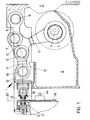
- a motor-driven crankshaft 3 is rotatably mounted for driving the central bearing 4 of a push rod 5, designed in the manner of a triangular lever.
- a push rod 5 designed in the manner of a triangular lever.
- the front rocker bearing 6 is articulated via a push rod 11 on the tappet 12 at the pivot point 19.
- the plunger 12 is in the direction of pressure, which is longitudinally displaceably mounted in the stamp center line 15 in the frame and carries the stamping stamp 16 at its end part opposite the pivot point 19.
- the stamping stamp 16 works with the stamping tool and in particular with the ejector stamping stamp 17 if a stamping piece 13 is present the embossing tool is oriented.
- the embossing piece 13 can be guided, for example, via a feed plate 18 in front of the embossing tool and can be led out of this area after the embossing.
- the feed plate is rotatable at 44 and is adjustably supported by a stepping device.
- the stepper drive can also be operated from the press drive consequences.
- the feed plate is pivoted out of the stamping area.
- the means for feeding the embossing blank into the feed plate, the means for the gradual movement and for the removal or ejection from the turntable are not shown in detail and can be constructed in a known manner.
- Position 27 indicates the position of the embossing piece 13 and the embossing surfaces of the embossing die 16 and the ejector embossing die 17.
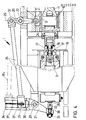
- the latter cooperates with an ejector rod 31 which can be actuated via a deflection drive in the direction of an ejector movement guided in the punch center line 15.
- the deflecting drive according to FIG. 4 consists, among other things, of a first double-armed deflecting lever 20, which is mounted fixed to the frame in the pivot point 22.
- the deflection lever is articulated at 24 on the tappet 12 and can thus be moved with it.
- Its second lever end carries a swivel joint 32 in which a push rod 26 is rotatably mounted.
- the fulcrums 22, 24 and 32 are located on a common central axis 29 for them.
- the fulcrum 22 on the frame side is arranged perpendicular to the stroke movement direction of the plunger 12 along its half stroke length.
- the pivot points 24 and 32 are spaced unevenly from the pivot point 22 of the bell crank.
- a second double-armed bell crank 21 is mounted so that it can swing. This has a long groove in which a sliding block 37 can be moved longitudinally and can be adjusted via a spindle drive 34, for example into position 37 1 .
- the bell crank is cranked to receive a fork 36, which carries a role to form an output fulcrum 33.
- the sliding block 37 carries as a pivot point 25 for the bell crank 21 a screw bolt with a transverse threaded hole for the spindle 34 and pin studs on both sides for the forked end of the pressure rod.
- FIGS. 2 and 3 show in particular the phases of the manufacture of the embossed part depending on the rotational movement of the central bearing 4.
- the frame-side link bearing 9 is arranged with respect to the punch center line 15 on the side opposite the crankshaft 3.
- the link 8 is movable with the connected rear swing arm bearings 7 around the handlebar bearing 9 in a circular arc with the radius dimension corresponding to the handlebar length.
- the distance from the center of the rear swing arm bearing 7 to the center of the central bearing 4 is greater than the possible greatest distance from the center of the central bearing 4 to Stamp center line 15, measured as the distance between the center of the center bearing 4 and the center of the rear rocker arm 7.
- the distance from the center of the front rocker arm 6 to the center of the rear rocker arm 7 and the distance from the center of the front rocker arm 6 to the center of the center arm 4 is designed so that the center of the front rocker bearing 6 whenever the central bearing 4 assumes a position that corresponds to the front dead center T of the plunger 12 is on the side towards the punch center line 15, which is associated with the frame-side link bearing 9.
- the center bearing 4 is in a position which corresponds to the rear dead center T h of the tappet 12, the center of the front rocker bearing 6 lies on the side of the punch center line 15 which is to be assigned to the crankshaft 3.
- T h in the right part of the curve 43 marks the beginning of the dead center position of the plunger 12 while Continue to move crankshaft 3, center bearing 4 and triangular lever 5.
- the crankshaft 3 rotates in the direction of the arrow 38, the embossing piece is changed after reaching the rear dead center.
- the embossing piece is carried into the embossing tool by the embossing stamp 16.
- the acceleration phase is ended approximately at point 41; the tappet is braked at 41 until it reaches the front dead center T as a result of the movement of the front rocker bearing 6 into the left curve part.
- the finished embossed part for example a coin or medal
- the takeover of the coin into the feed plate 18 takes place in a period of greatly slowing movement of the plunger up to the point 42 shown
- Driving the plunger can be driven and the ejector stamp 17 can be carried at least for the area of the restoring movement of the plunger via the deflection gear in the sense of an ejector movement, so that even for the time after embossing the finished part by the stamp 16 and the ejector stamp 17 and between them up to Transfer to the feed plate 18 is performed on all sides, possibly including a minor game.
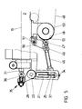
- the deflection lever 21 which is placed on the end 28 of the ejector stamp and is embodied as shown in FIG. 4, is acted upon by a push rod 45, which is articulated via a fulcrum 46 on a control lever 50.
- the control lever can be pivoted about a fulcrum 51 and is placed against the control cam 52 by means of a force accumulator (not shown) by means of a control roller 47, which has curve components 53 for adjusting the push rod.
- the control cam is mounted in a rotating manner and moved by a drive pulley 48 which is connected to the tappet drive via a belt drive 49.
- the adjustment of the cam plate 52 leads to an ejector movement of the ejector plunger synchronously with the plunger return movement in the sense of the description in FIG. 4.
Landscapes
- Engineering & Computer Science (AREA)
- Mechanical Engineering (AREA)
- Press Drives And Press Lines (AREA)
- Shaping Metal By Deep-Drawing, Or The Like (AREA)
Applications Claiming Priority (2)
| Application Number | Priority Date | Filing Date | Title |
|---|---|---|---|
| DE3230958A DE3230958A1 (de) | 1982-08-20 | 1982-08-20 | Muenzpraegepresse mit massnahmen fuer die allseitige fuehrung des praegestueckes in der presse |
| DE3230958 | 1982-08-20 |
Publications (3)
| Publication Number | Publication Date |
|---|---|
| EP0101590A2 true EP0101590A2 (fr) | 1984-02-29 |
| EP0101590A3 EP0101590A3 (en) | 1985-01-16 |
| EP0101590B1 EP0101590B1 (fr) | 1987-07-01 |
Family
ID=6171281
Family Applications (1)
| Application Number | Title | Priority Date | Filing Date |
|---|---|---|---|
| EP83107727A Expired EP0101590B1 (fr) | 1982-08-20 | 1983-08-05 | Presse d'estampage de monnaie avec des moyens pour le guidage universel de la pièce d'estampage dans la presse |
Country Status (3)
| Country | Link |
|---|---|
| EP (1) | EP0101590B1 (fr) |
| JP (1) | JPH0712491B2 (fr) |
| DE (2) | DE3230958A1 (fr) |
Cited By (4)
| Publication number | Priority date | Publication date | Assignee | Title |
|---|---|---|---|---|
| EP0718091A1 (fr) * | 1994-12-23 | 1996-06-26 | SCHULER PRESSEN GmbH & Co. | Presse d'estampage de monnaie |
| EP0718092A1 (fr) | 1994-12-23 | 1996-06-26 | SCHULER PRESSEN GmbH & Co. | Presse d'estampage de monnaie |
| US6708609B1 (en) | 1999-07-29 | 2004-03-23 | Schuler Pressen Gmbh & Co. Kg | Press product line |
| WO2019076628A1 (fr) * | 2017-10-17 | 2019-04-25 | Schuler Pressen Gmbh | Presse d'estampage et procédé servant à estamper un rond |
Families Citing this family (7)
| Publication number | Priority date | Publication date | Assignee | Title |
|---|---|---|---|---|
| DE4239617A1 (de) * | 1992-11-25 | 1994-05-26 | Lothar Wanzke | Prägeeinrichtung |
| DE19846951A1 (de) * | 1998-10-12 | 2000-04-20 | Strip S D O O Podjetje Za Svet | Presse mit Kniehebelantrieb |
| CN102126301B (zh) * | 2010-12-03 | 2013-11-27 | 广东工业大学 | 伺服机械压力机三角肘杆工作机构的优化设计方法 |
| DE102015117200B4 (de) | 2015-10-08 | 2018-03-15 | Schuler Pressen Gmbh | Prägepresse und Verfahren zu deren Betrieb |
| CN111231557B (zh) * | 2019-09-27 | 2021-07-27 | 广西科技大学 | 一种夹片全自动双头压字机机构 |
| CN111231556B (zh) * | 2019-09-27 | 2021-07-27 | 广西科技大学 | 一种夹片全自动双头压字机 |
| CN119035350B (zh) * | 2024-09-23 | 2025-04-25 | 绍兴新华制盖有限公司 | 用于全自动凸字铣字机的凸字工位及送料方法 |
Family Cites Families (5)
| Publication number | Priority date | Publication date | Assignee | Title |
|---|---|---|---|---|
| DE157536C (fr) * | ||||
| FR743842A (fr) * | 1933-04-07 | |||
| CH383167A (de) * | 1960-06-13 | 1964-10-15 | Smeralovy Z Narodni Podnik | Auswerfvorrichtung für automatische Pressen, insbesondere für Stufenpressen |
| US3661008A (en) * | 1970-03-17 | 1972-05-09 | Wickman Mach Tool Sales Ltd | Presses |
| DE2742041A1 (de) * | 1977-09-19 | 1979-04-05 | Schuler Gmbh L | Vorrichtung zum auswerfen von werkstuecken aus matrizen |
-
1982
- 1982-08-20 DE DE3230958A patent/DE3230958A1/de not_active Withdrawn
-
1983
- 1983-08-05 EP EP83107727A patent/EP0101590B1/fr not_active Expired
- 1983-08-05 DE DE8383107727T patent/DE3372273D1/de not_active Expired
- 1983-08-19 JP JP58150434A patent/JPH0712491B2/ja not_active Expired - Lifetime
Cited By (5)
| Publication number | Priority date | Publication date | Assignee | Title |
|---|---|---|---|---|
| EP0718091A1 (fr) * | 1994-12-23 | 1996-06-26 | SCHULER PRESSEN GmbH & Co. | Presse d'estampage de monnaie |
| EP0718092A1 (fr) | 1994-12-23 | 1996-06-26 | SCHULER PRESSEN GmbH & Co. | Presse d'estampage de monnaie |
| US6708609B1 (en) | 1999-07-29 | 2004-03-23 | Schuler Pressen Gmbh & Co. Kg | Press product line |
| WO2019076628A1 (fr) * | 2017-10-17 | 2019-04-25 | Schuler Pressen Gmbh | Presse d'estampage et procédé servant à estamper un rond |
| US11453039B2 (en) | 2017-10-17 | 2022-09-27 | Schuler Pressen Gmbh | Stamping press and method for stamping a round blank |
Also Published As
| Publication number | Publication date |
|---|---|
| DE3230958A1 (de) | 1984-02-23 |
| EP0101590B1 (fr) | 1987-07-01 |
| JPH0712491B2 (ja) | 1995-02-15 |
| JPS5954424A (ja) | 1984-03-29 |
| DE3372273D1 (en) | 1987-08-06 |
| EP0101590A3 (en) | 1985-01-16 |
Similar Documents
| Publication | Publication Date | Title |
|---|---|---|
| DE3322944C2 (de) | Matrizenauswerfer-Vorrichtung für Mehrstufen-Umformmaschinen | |
| EP0085387B1 (fr) | Appareil pour couper et rainurer des bandes en mouvement, en particulier des bandes de papier | |
| DD151134A1 (de) | Antrieb fuer funktionsgruppen in bogenfuehrungszylindern von druckmaschinen | |
| EP0101590B1 (fr) | Presse d'estampage de monnaie avec des moyens pour le guidage universel de la pièce d'estampage dans la presse | |
| EP0384979A1 (fr) | Dispositif de séparation pour une pile de corps d'ouvrage | |
| CH616110A5 (fr) | ||
| DE1940395A1 (de) | Schmiedepresse | |
| EP0330914A1 (fr) | Dispositif d'éjection des pièces hors des matrices dans une presse de formage | |
| EP1371588B1 (fr) | Dispositif de positionnement d'une barre à pinces d'une machine de poiçonnage et d'estampage de feuilles | |
| DE3731216C2 (fr) | ||
| DE3347786C2 (de) | Walzenvorschubeinrichtung | |
| EP0640547A1 (fr) | Casier rotatif pour piles sur un dispositif à mouvement croisé pour produits imprimés | |
| DE69104406T2 (de) | Vorrichtung zum Einrütteln von Blättern. | |
| EP0082260B1 (fr) | Dispositif d'alignement latéral de feuilles pour une machine à imprimer | |
| EP1941957A1 (fr) | Dispositif d'alimentation intermittente d'un demi-produit en forme de bande ou de fil dans une presse | |
| EP0063717B1 (fr) | Transmission pour l'exécution de mouvements comportant des temps d'arrêt intercalaires | |
| EP0151204B1 (fr) | Presse à frapper les monnaies | |
| DD278538A5 (de) | Einrichtung zur steuerung der werkzeugstellung in abhaengigkeit von der hubposition | |
| DE2148528C3 (de) | Auswerfervorrichtung zum Ausschieben von Preßteilen aus den ortsfesten Matrizen von Eindruck-, Doppeldruck- oder Mehrstufenpressen | |
| DE19501798A1 (de) | Verfahren und Vorrichtung zum Ausrichten eines Bogens auf dem Anlegetisch einer Bogenrotationsdruckmaschine | |
| DE2414442C2 (de) | Auswerfeinrichtung zum Auswerfen von Preßteilen aus der Matrize einer Presse | |
| EP1004394B9 (fr) | Porte-outil pour machine-outil | |
| EP0541835B1 (fr) | Dispositif de transport pour bonbons | |
| DE4324199C1 (de) | Vorrichtung zur symmetrischen Verstellung eines Falzwalzenspaltes in einem Schwertfalzwerk | |
| EP0188648A1 (fr) | Presse de transfert |
Legal Events
| Date | Code | Title | Description |
|---|---|---|---|
| PUAI | Public reference made under article 153(3) epc to a published international application that has entered the european phase |
Free format text: ORIGINAL CODE: 0009012 |
|
| AK | Designated contracting states |
Designated state(s): BE DE FR GB IT |
|
| PUAL | Search report despatched |
Free format text: ORIGINAL CODE: 0009013 |
|
| AK | Designated contracting states |
Designated state(s): BE DE FR GB IT |
|
| 17P | Request for examination filed |
Effective date: 19850711 |
|
| 17Q | First examination report despatched |
Effective date: 19860424 |
|
| GRAA | (expected) grant |
Free format text: ORIGINAL CODE: 0009210 |
|
| AK | Designated contracting states |
Kind code of ref document: B1 Designated state(s): BE DE FR GB IT |
|
| ET | Fr: translation filed | ||
| REF | Corresponds to: |
Ref document number: 3372273 Country of ref document: DE Date of ref document: 19870806 |
|
| ITF | It: translation for a ep patent filed | ||
| PLBE | No opposition filed within time limit |
Free format text: ORIGINAL CODE: 0009261 |
|
| STAA | Information on the status of an ep patent application or granted ep patent |
Free format text: STATUS: NO OPPOSITION FILED WITHIN TIME LIMIT |
|
| 26N | No opposition filed | ||
| ITTA | It: last paid annual fee | ||
| REG | Reference to a national code |
Ref country code: GB Ref legal event code: IF02 |
|
| PGFP | Annual fee paid to national office [announced via postgrant information from national office to epo] |
Ref country code: GB Payment date: 20020723 Year of fee payment: 20 |
|
| PGFP | Annual fee paid to national office [announced via postgrant information from national office to epo] |
Ref country code: BE Payment date: 20020821 Year of fee payment: 20 |
|
| PGFP | Annual fee paid to national office [announced via postgrant information from national office to epo] |
Ref country code: FR Payment date: 20020823 Year of fee payment: 20 |
|
| PGFP | Annual fee paid to national office [announced via postgrant information from national office to epo] |
Ref country code: DE Payment date: 20021011 Year of fee payment: 20 |
|
| PG25 | Lapsed in a contracting state [announced via postgrant information from national office to epo] |
Ref country code: GB Free format text: LAPSE BECAUSE OF EXPIRATION OF PROTECTION Effective date: 20030804 |
|
| REG | Reference to a national code |
Ref country code: GB Ref legal event code: PE20 |