EP0101917A1 - Outil d'alésage - Google Patents
Outil d'alésage Download PDFInfo
- Publication number
- EP0101917A1 EP0101917A1 EP83107265A EP83107265A EP0101917A1 EP 0101917 A1 EP0101917 A1 EP 0101917A1 EP 83107265 A EP83107265 A EP 83107265A EP 83107265 A EP83107265 A EP 83107265A EP 0101917 A1 EP0101917 A1 EP 0101917A1
- Authority
- EP
- European Patent Office
- Prior art keywords
- tool
- shank
- chuck
- pull rod
- tool head
- Prior art date
- Legal status (The legal status is an assumption and is not a legal conclusion. Google has not performed a legal analysis and makes no representation as to the accuracy of the status listed.)
- Granted
Links
Images

Classifications
-
- B—PERFORMING OPERATIONS; TRANSPORTING
- B23—MACHINE TOOLS; METAL-WORKING NOT OTHERWISE PROVIDED FOR
- B23B—TURNING; BORING
- B23B29/00—Holders for non-rotary cutting tools; Boring bars or boring heads; Accessories for tool holders
- B23B29/24—Tool holders for a plurality of cutting tools, e.g. turrets
- B23B29/32—Turrets adjustable by power drive, i.e. turret heads
-
- G—PHYSICS
- G01—MEASURING; TESTING
- G01B—MEASURING LENGTH, THICKNESS OR SIMILAR LINEAR DIMENSIONS; MEASURING ANGLES; MEASURING AREAS; MEASURING IRREGULARITIES OF SURFACES OR CONTOURS
- G01B11/00—Measuring arrangements characterised by the use of optical techniques
- G01B11/16—Measuring arrangements characterised by the use of optical techniques for measuring the deformation in a solid, e.g. optical strain gauge
-
- B—PERFORMING OPERATIONS; TRANSPORTING
- B23—MACHINE TOOLS; METAL-WORKING NOT OTHERWISE PROVIDED FOR
- B23B—TURNING; BORING
- B23B29/00—Holders for non-rotary cutting tools; Boring bars or boring heads; Accessories for tool holders
- B23B29/04—Tool holders for a single cutting tool
- B23B29/046—Tool holders for a single cutting tool with an intermediary toolholder
-
- B—PERFORMING OPERATIONS; TRANSPORTING
- B23—MACHINE TOOLS; METAL-WORKING NOT OTHERWISE PROVIDED FOR
- B23B—TURNING; BORING
- B23B29/00—Holders for non-rotary cutting tools; Boring bars or boring heads; Accessories for tool holders
- B23B29/24—Tool holders for a plurality of cutting tools, e.g. turrets
- B23B29/244—Toolposts, i.e. clamping quick-change toolholders, without description of the angular positioning device
-
- B—PERFORMING OPERATIONS; TRANSPORTING
- B23—MACHINE TOOLS; METAL-WORKING NOT OTHERWISE PROVIDED FOR
- B23Q—DETAILS, COMPONENTS, OR ACCESSORIES FOR MACHINE TOOLS, e.g. ARRANGEMENTS FOR COPYING OR CONTROLLING; MACHINE TOOLS IN GENERAL CHARACTERISED BY THE CONSTRUCTION OF PARTICULAR DETAILS OR COMPONENTS; COMBINATIONS OR ASSOCIATIONS OF METAL-WORKING MACHINES, NOT DIRECTED TO A PARTICULAR RESULT
- B23Q17/00—Arrangements for observing, indicating or measuring on machine tools
- B23Q17/24—Arrangements for observing, indicating or measuring on machine tools using optics or electromagnetic waves
-
- B—PERFORMING OPERATIONS; TRANSPORTING
- B23—MACHINE TOOLS; METAL-WORKING NOT OTHERWISE PROVIDED FOR
- B23B—TURNING; BORING
- B23B2260/00—Details of constructional elements
- B23B2260/084—Hirth couplings
-
- Y—GENERAL TAGGING OF NEW TECHNOLOGICAL DEVELOPMENTS; GENERAL TAGGING OF CROSS-SECTIONAL TECHNOLOGIES SPANNING OVER SEVERAL SECTIONS OF THE IPC; TECHNICAL SUBJECTS COVERED BY FORMER USPC CROSS-REFERENCE ART COLLECTIONS [XRACs] AND DIGESTS
- Y10—TECHNICAL SUBJECTS COVERED BY FORMER USPC
- Y10T—TECHNICAL SUBJECTS COVERED BY FORMER US CLASSIFICATION
- Y10T279/00—Chucks or sockets
- Y10T279/17—Socket type
- Y10T279/17564—Loose jaws
- Y10T279/17598—Fixed cam and moving jaws
-
- Y—GENERAL TAGGING OF NEW TECHNOLOGICAL DEVELOPMENTS; GENERAL TAGGING OF CROSS-SECTIONAL TECHNOLOGIES SPANNING OVER SEVERAL SECTIONS OF THE IPC; TECHNICAL SUBJECTS COVERED BY FORMER USPC CROSS-REFERENCE ART COLLECTIONS [XRACs] AND DIGESTS
- Y10—TECHNICAL SUBJECTS COVERED BY FORMER USPC
- Y10T—TECHNICAL SUBJECTS COVERED BY FORMER US CLASSIFICATION
- Y10T409/00—Gear cutting, milling, or planing
- Y10T409/30—Milling
- Y10T409/309352—Cutter spindle or spindle support
- Y10T409/309408—Cutter spindle or spindle support with cutter holder
- Y10T409/309464—Cutter spindle or spindle support with cutter holder and draw bar
-
- Y—GENERAL TAGGING OF NEW TECHNOLOGICAL DEVELOPMENTS; GENERAL TAGGING OF CROSS-SECTIONAL TECHNOLOGIES SPANNING OVER SEVERAL SECTIONS OF THE IPC; TECHNICAL SUBJECTS COVERED BY FORMER USPC CROSS-REFERENCE ART COLLECTIONS [XRACs] AND DIGESTS
- Y10—TECHNICAL SUBJECTS COVERED BY FORMER USPC
- Y10T—TECHNICAL SUBJECTS COVERED BY FORMER US CLASSIFICATION
- Y10T82/00—Turning
- Y10T82/25—Lathe
- Y10T82/2585—Tool rest
- Y10T82/2591—Tool post
Definitions
- the invention relates to a divided tool with the features contained in the preamble of claim 1, as is known from EP-A1-0010074.
- the known tool of the type mentioned at the beginning contains prismatic guide surfaces at the point of separation between the tool shank and the tool head.
- the pull rod has a cylindrical pull head which engages in a recess of the tool head which is open on a narrow side. This recess has a keyhole-like cross-sectional shape. With this tool, the tool head can only be connected to the tool shank in a certain rotational position will.
- the tool head and tool shank are connected and disconnected on a movement path that is oriented approximately at right angles to the longitudinal axis of the tool shank.
- the invention has for its object to provide a divided tool of the type mentioned, the tool head is easily and quickly connectable and detachable with the tool shank and in the composite position has a high dimensional stability and stability even with changing cutting forces during the machining process. This object is achieved by the features listed in the characterizing part of patent claim 1.
- the coupling has an essentially rotationally symmetrical structure.
- This has the advantage that the tool head for connection to the tool shaft does not have to have a specific relative rotational position to the tool shaft. In every rotational position of the tool head, a secure gripping of its pull shank is guaranteed by the chuck of the coupling.
- the clamping head can be inserted with its traction shank into the chuck of the tool shank on a linear movement path, this movement path being aligned coaxially with the longitudinal axis of the chuck.
- the opening and closing movement of the chuck is carried out by a longitudinal displacement on the part of the drawbar.
- the pull rod is at least in the tightening direction in a positive connection with the chuck, so that the chuck carries out every tightening movement of the pull rod in the same size.
- the radially inward closing movement of the chuck is caused by the interaction of the outer cone arranged on part of its outer circumference area with a corresponding inner conical surface of the recess of the tool shank.
- the chuck executes both an axial movement corresponding to the longitudinal movement of the pull rod and a radially inward movement of the pliers.
- the jaw projections of the chuck grip behind the radially outward projection of the pull shaft of the tool head and take it along in the pulling direction of the pull rod.
- the chuck is opened by moving the pull rod in the direction of the tool head, in which the chuck is carried along.
- the characterizing feature of claim 3 ches 2 centering effect exerted axially on several points.
- the same goal is sought with regard to the radially inwardly directed forces exerted by the inner cone surfaces of the recess of the tool shank on the outer cone segments of the clamping jaws.
- Such a uniform closing movement is ensured if the chuck jaws of the chuck do not change their parallel position to the tool axis during the closing movement.
- the radially inward closing movement of the jaws of the chuck is already completed before the pull rod or the chuck have completed their axial movement in order to achieve the closing end position.
- they are securely held in radial closing position by their contact with the corresponding inner cylindrical surfaces of the tool shank via their cylindrical segment surfaces and in large-area contact with comparatively little surface pressure Are in contact, the wedge forces exerted by the chuck on the pull shaft or the effective wedge angle of these wedge forces are significantly reduced when the pull rod is tightened further.
- the chuck is only effective radially inward and thus still centering wedge forces on the traction shank of the tool head through the inner cone segment surfaces of the clamping jaws. This increases the Tension and positioning security of the subject matter of the invention or its coupling even under heavy, pulsating loads.
- the clamping jaws of the chuck lie both inside and outside in the region of two cones lying next to one another in the axial direction, both on the shank of the tool head and on the peripheral wall of the Recess of the tool shank.
- This at least four-point or four-surface contact on two reference parts means a static indeterminacy, by which it is not readily guaranteed that the respective conical contact surfaces bear against their corresponding counter surfaces.
- the clamping jaws are wedged between the traction shank of the tool head and the tool shank in approximately a common radial plane, while the other contact areas of the clamping jaws on the traction shank and on the tool shank in any case in the clamping end position in different axial positions grasp the inside and outside of the individual jaws or chuck.
- the bending forces introduced into the clamping jaws by the pull rod act in such a way that the clamping jaws can bend slightly in these areas and thus automatically compensate for the static uncertainties of the multi-range system of the clamping jaws of the chuck on the tool shank and on the pull shank of the tool head.
- the result is an effective multiple clamping of the tool head over a large axial length within the tool shaft.
- the characterizing feature of claim 11 ensures that a corresponding axial movement of the chuck is connected to the axial opening movement of the pull rod, which enables radial separation - the clamping jaws of the chuck.
- the characteristic of claim 12 favors easy opening and closing of the collet by its axial displacement within the tool shaft on the part of the pull rod.
- the characterizing feature of claim 14 first enables that the tool head can assume practically any desired rotational position with respect to the tool shank at comparatively narrow angular distances, the coupling being equally effective.
- the Hirth serration ensures the desired torsional strength of the connection between the tool head and the tool shank through the interlocking interlocking of the two-sided toothing.
- the Hirth toothing has the great advantage that it leads to an automatic centering of the tool head relative to the tool shaft or its central longitudinal axis when the pulling action acts axially on the pulling shaft of the tool head.
- the construction according to the invention enables the arrangement of at least one through hole from the outside of the tool head facing the tool cutting edge to the machine-side end of the drawbar.
- the axis of the through hole can even coincide with the central longitudinal axis of the entire tool and thus be completely independent of the respective rotational position of the tool head relative to the tool shank.
- This hole can be used to pass the light beam from an optical or electro-optical measuring system, which monitors, for example, the position and integrity of the cutting edge.
- the bore can serve for the passage of a coolant or lubricant. Can too there are several holes for different such purposes.
- a through hole passing through the pull rod and the pull shaft remains free from external interference during operation.
- the insertion of a seal between the extension of the pull rod and the pull shank leads to a friction which, for example when the pull rod is axially displaced in the opening direction, also transfers an axial movement to the pull shank and thus to the tool head and promotes its release from the tool shank.
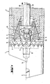
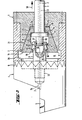
- the tool essentially consists of the tool shank 1, a pull rod 3 which is displaceably mounted in it in the longitudinal direction of the tool shank axis 2, the tool head 4 with a cutting body 5 made of hard metal, for example fastened at its front end, and one arranged in a front recess 6 of the tool shank 1, in total with 7 designated chuck.
- the pull rod 3 is by a power drive, not shown - e.g. a screw spindle or a hydraulic - in the direction of the shaft axis 2 between the open position (Fig. 1) and the closed position (Fig. 2) of the chuck 7.
- the tool head 4 is provided with a screwed-in pull shaft 8 which projects in the direction of the tool shaft 1 and which projects into the recess 6 of the tool shaft 1.
- the tool head 4 can be positively clamped by the pull rod 3 via the chuck 7 and the pull shaft 8 against the end face of the tool shaft 1, which in the case of the exemplary embodiments is formed by a Hirth toothing designated overall by 9.
- the Hirth serration 9 on the one hand enables the tool head 4 to be fixed in different rotational positions with respect to the tool shank 1. On the other hand, it is characterized by a self-centering effect when the pull rod 3 is pulled against the tool shank 1 in its tightening direction 10.
- the chuck 7 consists of a plurality of clamping jaws 11 running parallel to one another in the direction of the shaft axis 2 and surrounding the pull rod 3 and the clamping bolt 8. Between the individual clamping jaws 11 there is in each case a spring element 12 consisting of a rubber-elastic material, which laterally with the clamping jaws 10 is cohesively connected. The connection can be made for example by gluing or vulcanizing, so that the jaws 11 with the Spring elements 12 form a unit, namely the actual chuck 7.
- the spring elements 12 serve to automatically spread the clamping jaws 11 apart in the open position of the collet (FIG. 1) and thereby release the traction shank 8 of the tool head 4 in such a way that the tool head 4 can be detached from the tool shank 1 in the axial direction against the tightening direction 10.
- the pull rod 3 is provided in its area encompassed by the chuck 7 with an outwardly projecting, in particular ring-like radial projection 13, the flank 14 of which faces away from the tool head 4, both in the open and in the closed position of the chuck 7, for axial transmission of tension to the jaws 11 of inward, on the tie rod-side projections 15 is radially covered.
- the traction shank 8 of the tool head 4 is provided in its region encompassed by the chuck 7 with a radially outward, in particular ring-like projection 16.
- the flank 17 of the projection 16 facing away from the pull rod 3 is radially covered in the closed position (FIG. 2) of the chuck 7 for axial pull transmission to the tool head 4 by the inward, tension-side jaw protrusions 18.
- the flanks 17 remain apart from radial overlap with the clamping jaw projections 18.
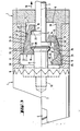
- the flank 17 facing away from the pull rod 3 (FIG. 3) of the radial projection 16 of the pull shank 8 is an outer conical surface which opens in the tightening direction 10 of the pull rod 3 and is designated by 19 in FIGS. 1, 2 and 4 and which in the closed position of the chuck 7 of the flanks 20 of the jaw protrusions 18 (FIG. 3), which are designed as cone segments, are acted upon.
- two outer cone surfaces 19 are arranged on the pull shaft 8 at an axial distance from one another.
- the jaw protrusions 18 corresponding to these outer cone surfaces 19 are designed as inner cone segment surfaces.
- the outer conical surfaces 19 of the traction shank 8 have the same diameter.
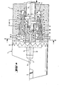
- the clamping jaws 11 have on the outer circumference of the chuck 7 axially spaced apart from one another in the embodiments according to FIGS. 3 and 4 two outer cone segments 21, 22 which close in the tightening direction 10 of the pull rod 3.
- the peripheral wall of the recess 6 in the tool shank 1 contains a number of inner cone surfaces 23, 24 which cooperate with the outer cone segments 21, 22 and correspond to the number of outer cone segments 21, 22 of each clamping jaw 11.
- the effective diameters of the outer cone segments 21, 22 of the clamping jaws 11, which are spaced apart from one another in the axial direction, are so different and graduated from one another that the effective diameter 39 of the outer cone segment 22 on the tie rod side is smaller than that of the outer cone segment 21 on the tool head side, and that each outer cone segment 21, 22 in the direction of the Tool head 4 connects a cylinder segment surface 25 or 26. Consequently, the clamping jaws 11 are supported via their outer cone segments 21, 22 on the corresponding inner cone surfaces 23, 24 of the tool shank 1 when the pull rod 3 is pushed in the direction of the tool head 4 and the chuck 7 is consequently open. On the other hand, when the pull rod 3 is tightened in its tightening direction 10 (FIGS. 3 and 4 upper half) and consequently the chuck 7 is closed, the clamping jaws 11 rest against corresponding inner cylindrical surfaces 27, 28 of the tool shank 1 via their cylindrical segment surfaces 25, 26.
- the cylinder segment surfaces 26 of the clamping jaws 11 remote from the tool head lie in the direction of the shaft axis 2 with their axial length 40 centrally between the tie rod contact flanks 29 of the clamping jaw projections 15 and the inner cone surfaces 20 of the clamping jaws 11 on the tool shaft side.
- the cylinder segment surfaces 25 of the clamping jaws facing the tool head 4 11 lie in approximately the same radial plane as the flanks 20 of the clamping jaws 11 facing the tool head 4 and designed as inner cone segment surfaces.
- the flanks 20 designed as inner cone segment surfaces form an angle 30 of approximately 30 ° with the tool shaft axis 2.
- On the clamping jaws 11 protruding inner projections 31 are arranged in the direction of the tool head 4 of the radial projection 13 of the pull rod 3.
- the traction shank 8 is connected to the remaining parts of the tool head 4 by means of a threaded connection 32.
- Pull rod 3 and pull shaft 8 are penetrated by at least one bore 33 or 34 running in the axial direction.
- the bores 33, 34 are part of a connecting path between the tool cutting edge of the cutting body 5 of the tool head 4 and an auxiliary unit (not shown) arranged on the machine-side end of the pull rod 3.
- the bores 33, 34 are aligned with one another and are used either to pass the light beam from an optical or electro-optical measuring system or also to pass coolant or lubricant through.
- the end of the pull rod 3 on the tool head side is guided axially displaceably by means of an axial extension shoulder 35 within a bore 36 made in the end of the pull shaft 8 of the tool head 4 on the pull rod side.
- This leadership between Drawbar 3 and drawbar 8 is liquid-tight.
- the seal between the extension lug 35 of the pull rod 3 and the pull shaft 8 is formed by a round cord ring 37 which surrounds the extension lug 35 and lies in an annular groove.
- the tool shank 1 is provided at its end on the tool head side with an axially effective, in particular annular, travel limit stop 38 for the opening movement of the chuck 7.
- the tool in the embodiment of FIG. 4 works as follows: When the chuck is in the open position (lower part), the clamping jaws 11 are in a spread, radially outer position. In this position, the traction shank 8 of the tool head 4 can freely enter the radial space between the clamping jaws 11 or can be pulled out of it in the direction of the axis 2. In this open position of the chuck 7, its radially outer surfaces bear with the outer cone segments 21, 22 on the corresponding inner cone surfaces 23, 24 of the tool shank 1.
- the pull rod 3 is tightened in the tightening direction 10.
- the jaws 11 of the chuck 7 slide with their outer cone segments 2.1, 22 initially over the inner cone surfaces 23, 24 of the tool shank 1, with the result that the jaws 11 are displaced radially inward. This means that the chuck closes.
- the pull rod 3 is tightened further, the mutual contact between the clamping jaws 11 and the tool shank 1 passes from the cone regions on both sides into the cylinder regions on both sides.
- the radially inward movement of the jaws 11 is complete. There is only one axial movement in the tightening direction 10 between the clamping jaws 11 and the tool shank 1.
- the clamping jaws 11 are wedged between the outer conical surfaces 19 of the pull shank 8 and in particular the inner cylinder surface 27 of the tool shank 1 on the tool head side, specifically in a plane perpendicular to the tool shank axis 2. Under the further tightening of the pull rod 3, the part of each clamping jaw 11 on the pull rod side acts as a two-armed lever.
- the two lever arm ends are approximately through the tie rod contact flank 29 of the jaw projection 15 and the tie rod side, as an inner cone segment surface. formed flank 20 of the clamping jaw 11 is formed, while the pull rod-side cylinder segment surface 26 of each clamping jaw 11 forms the counter bearing of this two-armed lever.
- the pull rod 3 is pushed back against the tightening direction 10.
- the radial projection 13 of the pull rod 3 abuts against the inner projection 31 of the clamping jaws 11 and pushes them out of their clamping position in the direction of the tool head 4.
- the tool head 4 is also carried along by the round cord ring 37 via the pull shaft 8.
- the chuck 7 opens under the pressure of the spring elements 12.
- the clamping jaws 11 come apart.
- the flanks 20 of the clamping jaws are no longer in radial overlap with the outer conical surfaces 19 of the tension shank 8, the tool head 4 can be removed from the tool shank 1 unhindered.
Landscapes
- Engineering & Computer Science (AREA)
- Mechanical Engineering (AREA)
- Physics & Mathematics (AREA)
- General Physics & Mathematics (AREA)
- Optics & Photonics (AREA)
- Gripping On Spindles (AREA)
Priority Applications (1)
| Application Number | Priority Date | Filing Date | Title |
|---|---|---|---|
| AT83107265T ATE19976T1 (de) | 1982-07-30 | 1983-07-25 | Geteiltes werkzeug fuer die spanabhebende bearbeitung. |
Applications Claiming Priority (6)
| Application Number | Priority Date | Filing Date | Title |
|---|---|---|---|
| DE19823228521 DE3228521C2 (de) | 1982-07-30 | 1982-07-30 | Werkzeug-Wechselhalter |
| DE3228521 | 1982-07-30 | ||
| DE3243948 | 1982-11-27 | ||
| DE19823243948 DE3243948A1 (de) | 1982-11-27 | 1982-11-27 | Teilbares werkzeug fuer die spanabhebende bearbeitung |
| DE19833309922 DE3309922A1 (de) | 1983-03-19 | 1983-03-19 | Werkzeugwechselhalter |
| DE3309922 | 1983-03-19 |
Publications (2)
| Publication Number | Publication Date |
|---|---|
| EP0101917A1 true EP0101917A1 (fr) | 1984-03-07 |
| EP0101917B1 EP0101917B1 (fr) | 1986-05-28 |
Family
ID=27190274
Family Applications (1)
| Application Number | Title | Priority Date | Filing Date |
|---|---|---|---|
| EP83107265A Expired EP0101917B1 (fr) | 1982-07-30 | 1983-07-25 | Outil d'alésage |
Country Status (6)
| Country | Link |
|---|---|
| US (1) | US4632614A (fr) |
| EP (1) | EP0101917B1 (fr) |
| KR (1) | KR860001709B1 (fr) |
| CA (1) | CA1225822A (fr) |
| DE (1) | DE3363749D1 (fr) |
| ES (1) | ES524580A0 (fr) |
Cited By (13)
| Publication number | Priority date | Publication date | Assignee | Title |
|---|---|---|---|---|
| DE3507225A1 (de) * | 1985-03-01 | 1986-09-04 | Fried. Krupp Gmbh, 4300 Essen | Werkzeugeinrichtung mit wechselbarem werkzeugkopf |
| DE3536183A1 (de) * | 1985-03-01 | 1986-09-04 | Fried. Krupp Gmbh, 4300 Essen | Werkzeugeinrichtung mit wechselbarem werkzeugkopf |
| EP0169543A3 (en) * | 1984-07-23 | 1988-01-20 | Hermann Dipl.-Ing. Kastner | Divisible tool for machining |
| EP0195246A3 (fr) * | 1985-03-13 | 1988-07-27 | Otto Zettl | Accouplement à interchange rapide pour outils de coupe |
| US4784542A (en) * | 1985-03-01 | 1988-11-15 | Fried. Krupp Gesellschaft Mit Beschrankter Haftung | Tool-mounting assembly having an exchangeable tool head |
| EP0299141A1 (fr) * | 1987-04-15 | 1989-01-18 | Axa-Entwicklungs- Und Maschinenbaugesellschaft Für Produktionstechnische Anlagen Und Geräte Mbh | Machine-outil, poinçonneuse, ou pareille machine avec un dispositif de fixation d'outil pour changement automatique d'outil |
| AU580688B2 (en) * | 1985-09-14 | 1989-01-27 | Fried Krupp Gesellschaft Mit Beschrankter Haftung | Tool coupling |
| EP0416611A3 (en) * | 1989-09-07 | 1991-05-29 | Traub Ag | Installation of an exchangeable tool holder on the turret of a lathe |
| US5065492A (en) * | 1988-10-01 | 1991-11-19 | Krupp Widia Gmbh | Method of and assembly for releasably connecting a tool head to a tool base holder of a tool turret machine tool |
| WO1999042238A1 (fr) * | 1996-04-08 | 1999-08-26 | Bissett Kevin J | Ensemble poupee porte-piece a couplage rapide |
| DE112010004240B4 (de) * | 2009-11-02 | 2014-06-18 | Kennametal Inc. | Werkzeughalter sowie Kühlmittelkupplungsystem bestehend aus einem Werkzeughalter und einem Werkzeughalterstützglied |
| US9314985B2 (en) | 2011-09-27 | 2016-04-19 | Kennametal Inc. | Coated pelletizing extrusion dies and method for making the same |
| CN106756716A (zh) * | 2016-12-29 | 2017-05-31 | 芜湖新兴铸管有限责任公司 | 一种铸管喷锌生产设备组合顶尖 |
Families Citing this family (32)
| Publication number | Priority date | Publication date | Assignee | Title |
|---|---|---|---|---|
| SE454488B (sv) * | 1986-10-31 | 1988-05-09 | Seco Tools Ab | Forfarande och anordning for att astadkomma hopkoppling av en hallarkropp med ett verktygshuvud |
| US4998851A (en) * | 1987-12-11 | 1991-03-12 | Gte Valenite Corporation | Vibration dampened boring bar |
| DE3807887A1 (de) * | 1988-03-10 | 1989-09-21 | Hertel Ag Werkzeuge Hartstoff | Werkzeugwechselhalter |
| US4919023A (en) * | 1988-03-22 | 1990-04-24 | Bloink Harry W | Quick-change tool adapter |
| US4871286A (en) * | 1988-10-24 | 1989-10-03 | Gte Valenite Corporation | Grooving or threading tool |
| SE462554B (sv) * | 1989-02-01 | 1990-07-16 | Sandvik Ab | Spaennanordning foer verktyg |
| US5090280A (en) * | 1990-03-21 | 1992-02-25 | Kennametal Inc. | Tool holder assembly with angular adjustment mechanism |
| US5245896A (en) * | 1992-08-19 | 1993-09-21 | Kennametal Inc. | Quick-change tool holder with center height adjustment mechanism |
| DE4228558C1 (de) * | 1992-08-27 | 1994-02-10 | Gildemeister Devlieg System | Spannvorrichtung für Werkzeughalter |
| US5261302A (en) * | 1992-10-07 | 1993-11-16 | Kennametal Inc. | Quick-change tool holder with adjustment mechanism for repeatable center-height adjustment |
| DE19543734C1 (de) * | 1995-11-24 | 1997-05-07 | Benteler Werke Ag | Werkzeughaltevorrichtung für den automatischen Werkzeugwechsel |
| US5873682A (en) * | 1997-04-14 | 1999-02-23 | Koyo Corporation Of Usa | Pivoting tool holder |
| SE512318C2 (sv) * | 1997-08-29 | 2000-02-28 | Sandvik Ab | Verktygskoppling |
| US5971681A (en) * | 1997-10-10 | 1999-10-26 | Kurt Manufacturing Company, Inc. | Drawbar guide ring with drive keys |
| DE29720447U1 (de) * | 1997-11-18 | 1998-04-02 | MARANTEC Antriebs- und Steuerungstechnik GmbH & Co. Produktions-KG, 33428 Marienfeld | Antriebsspindel |
| SE517192C2 (sv) * | 1999-02-26 | 2002-05-07 | Sandvik Ab | Verktygskoppling |
| SE514356C2 (sv) * | 1999-06-09 | 2001-02-12 | Sandvik Ab | Hållare för lösgörbar montering av skärverktyg |
| SE516003C2 (sv) * | 2000-03-02 | 2001-11-05 | Sandvik Ab | Verktyg med snedställda monteringsytor mellan hållar- och verktygsdel |
| SE516501C2 (sv) * | 2000-05-18 | 2002-01-22 | Sandvik Ab | Verktygskoppling |
| RU2242331C2 (ru) * | 2003-02-17 | 2004-12-20 | Государственное образовательное учреждение высшего профессионального образования "Алтайский государственный технический университет им. И.И. Ползунова" | Модульная инструментальная оснастка |
| SE527703C2 (sv) * | 2004-08-19 | 2006-05-16 | Sandvik Intellectual Property | Roterbart verktyg samt skärhuvud med axiella serraterade ingreppsorgan |
| DE102009003287A1 (de) * | 2009-05-20 | 2010-11-25 | Hilti Aktiengesellschaft | Bohrer |
| JP5272935B2 (ja) * | 2009-07-09 | 2013-08-28 | 村田機械株式会社 | カップリング装置 |
| CN102686343B (zh) * | 2009-12-14 | 2015-02-18 | 京瓷株式会社 | 切削工具用刀夹及切削工具、以及使用该切削工具的切削加工物的制造方法 |
| CN103717333A (zh) * | 2011-08-02 | 2014-04-09 | 伊斯卡有限公司 | 模块化切削工具支架及其夹持机构 |
| DE102012224524B4 (de) * | 2012-12-28 | 2014-07-10 | Illinois Tool Works Inc. | Kopplungsvorrichtung für eine Antriebsvorrichtung sowie Antriebseinrichtung |
| DE102013218884B4 (de) | 2013-09-19 | 2015-05-21 | Kennametal Inc. | Spanendes Werkzeug |
| US9702385B2 (en) * | 2014-05-15 | 2017-07-11 | Iscar, Ltd. | Machine tool assembly configured for swift disassembly |
| US10252389B2 (en) | 2017-07-05 | 2019-04-09 | Kennametal Inc. | Quick-change clamping unit for toolholder and method of using same |
| CN110576199B (zh) * | 2018-06-11 | 2021-08-17 | 河南平高电气股份有限公司 | 端面切槽刀体 |
| CN114025903A (zh) * | 2019-07-08 | 2022-02-08 | 株式会社泰珂洛 | 切削刀具 |
| KR102758374B1 (ko) * | 2020-02-20 | 2025-01-22 | 주식회사 디엔솔루션즈 | 공작기계의 롱보링바 장치 |
Citations (5)
| Publication number | Priority date | Publication date | Assignee | Title |
|---|---|---|---|---|
| DE2736412A1 (de) * | 1976-08-24 | 1978-03-02 | Kennametal Inc | Spannvorrichtung |
| DE2234389B2 (de) * | 1972-07-13 | 1979-03-22 | Bernhard 3011 Garbsen Rau | Werkzeughalter für nicht umlaufende Schneidwerkzeuge an Drehmaschinen |
| DE2706469B2 (de) * | 1977-02-16 | 1979-04-12 | Kurt 5900 Siegen Klur | Auf den Support von Drehmaschinen aufsetzbare Werkzeughalterung |
| EP0010074A1 (fr) * | 1978-09-26 | 1980-04-16 | Santrade Ltd. | Outil de coupe |
| DE2106854B2 (de) * | 1971-02-13 | 1981-06-11 | Hans 8502 Zirndorf Heinlein | Werkzeughalter |
Family Cites Families (14)
| Publication number | Priority date | Publication date | Assignee | Title |
|---|---|---|---|---|
| DE1159733B (de) * | 1958-05-17 | 1963-12-19 | Ernst Matheis | Stahlhalter |
| US3242819A (en) * | 1964-04-06 | 1966-03-29 | Sundstrand Corp | Tool adapter with retention means |
| US3635108A (en) * | 1970-03-09 | 1972-01-18 | Us Navy | Laser-guided boring tool for deep hole boring |
| US3650018A (en) * | 1970-08-06 | 1972-03-21 | Cincinnati Milacron Inc | Machine tool with tool changing and transferring means |
| US3762271A (en) * | 1971-06-01 | 1973-10-02 | Ratier Sa Forest | Device for clamping a taper shank tool-holder in the nose of a rotary machine-tool spindle |
| DE2230143C3 (de) * | 1972-06-21 | 1979-11-29 | Schiess Ag, 4000 Duesseldorf | Werkzeugsupport mit darin lotrecht verfahrbarem Meißelschieber an einer Werkzeugmaschine mit einem dem Werkzeugsupport zugeordneten Wechselmagazin |
| US3868886A (en) * | 1973-07-05 | 1975-03-04 | Ex Cell O Corp | Tool holding assembly |
| US3889962A (en) * | 1974-01-08 | 1975-06-17 | Hardinge Brothers Inc | Seals for collets |
| US3975984A (en) * | 1975-09-19 | 1976-08-24 | Caterpillar Tractor Co. | Self aligning collect for machine tools |
| CH612869A5 (fr) * | 1977-08-15 | 1979-08-31 | Emile Albert Minder | |
| US4334811A (en) * | 1979-10-12 | 1982-06-15 | Werkzeugmaschinenfabrik Oerlikon-Buhrle Ag | Spindle extension, especially for drilling and milling machines |
| DE3007440A1 (de) * | 1980-02-28 | 1981-09-17 | Fried. Krupp Gmbh, 4300 Essen | Werkzeugeinrichtung mit wechselbarem werkzeugtraeger |
| DE8115135U1 (de) * | 1981-05-21 | 1981-10-01 | Benz GmbH Werkzeug- u. Maschinenbau KG, 7612 Hasloch | Schnellwechselwerkzeughalter, insbesondere fuer drehmaschinen |
| EP0132825A1 (fr) * | 1983-07-23 | 1985-02-13 | Hermann Dipl.-Ing. Kastner | Outil divisible pour l'usinage |
-
1983
- 1983-07-25 DE DE8383107265T patent/DE3363749D1/de not_active Expired
- 1983-07-25 EP EP83107265A patent/EP0101917B1/fr not_active Expired
- 1983-07-27 CA CA000433268A patent/CA1225822A/fr not_active Expired
- 1983-07-29 ES ES524580A patent/ES524580A0/es active Granted
- 1983-07-29 US US06/527,257 patent/US4632614A/en not_active Expired - Fee Related
- 1983-07-30 KR KR1019830003573A patent/KR860001709B1/ko not_active Expired
Patent Citations (5)
| Publication number | Priority date | Publication date | Assignee | Title |
|---|---|---|---|---|
| DE2106854B2 (de) * | 1971-02-13 | 1981-06-11 | Hans 8502 Zirndorf Heinlein | Werkzeughalter |
| DE2234389B2 (de) * | 1972-07-13 | 1979-03-22 | Bernhard 3011 Garbsen Rau | Werkzeughalter für nicht umlaufende Schneidwerkzeuge an Drehmaschinen |
| DE2736412A1 (de) * | 1976-08-24 | 1978-03-02 | Kennametal Inc | Spannvorrichtung |
| DE2706469B2 (de) * | 1977-02-16 | 1979-04-12 | Kurt 5900 Siegen Klur | Auf den Support von Drehmaschinen aufsetzbare Werkzeughalterung |
| EP0010074A1 (fr) * | 1978-09-26 | 1980-04-16 | Santrade Ltd. | Outil de coupe |
Cited By (15)
| Publication number | Priority date | Publication date | Assignee | Title |
|---|---|---|---|---|
| EP0169543A3 (en) * | 1984-07-23 | 1988-01-20 | Hermann Dipl.-Ing. Kastner | Divisible tool for machining |
| DE3507225A1 (de) * | 1985-03-01 | 1986-09-04 | Fried. Krupp Gmbh, 4300 Essen | Werkzeugeinrichtung mit wechselbarem werkzeugkopf |
| DE3536183A1 (de) * | 1985-03-01 | 1986-09-04 | Fried. Krupp Gmbh, 4300 Essen | Werkzeugeinrichtung mit wechselbarem werkzeugkopf |
| US4784542A (en) * | 1985-03-01 | 1988-11-15 | Fried. Krupp Gesellschaft Mit Beschrankter Haftung | Tool-mounting assembly having an exchangeable tool head |
| EP0195246A3 (fr) * | 1985-03-13 | 1988-07-27 | Otto Zettl | Accouplement à interchange rapide pour outils de coupe |
| AU580688B2 (en) * | 1985-09-14 | 1989-01-27 | Fried Krupp Gesellschaft Mit Beschrankter Haftung | Tool coupling |
| EP0299141A1 (fr) * | 1987-04-15 | 1989-01-18 | Axa-Entwicklungs- Und Maschinenbaugesellschaft Für Produktionstechnische Anlagen Und Geräte Mbh | Machine-outil, poinçonneuse, ou pareille machine avec un dispositif de fixation d'outil pour changement automatique d'outil |
| US4976575A (en) * | 1987-04-15 | 1990-12-11 | AXA-Entwicklungs- und Maschinenbau- gesellschaft fur produktionstechnisch e anlagen und Gerate mbH | Tool holding system for automatic tool changing |
| US5065492A (en) * | 1988-10-01 | 1991-11-19 | Krupp Widia Gmbh | Method of and assembly for releasably connecting a tool head to a tool base holder of a tool turret machine tool |
| EP0416611A3 (en) * | 1989-09-07 | 1991-05-29 | Traub Ag | Installation of an exchangeable tool holder on the turret of a lathe |
| WO1999042238A1 (fr) * | 1996-04-08 | 1999-08-26 | Bissett Kevin J | Ensemble poupee porte-piece a couplage rapide |
| DE112010004240B4 (de) * | 2009-11-02 | 2014-06-18 | Kennametal Inc. | Werkzeughalter sowie Kühlmittelkupplungsystem bestehend aus einem Werkzeughalter und einem Werkzeughalterstützglied |
| US8807880B2 (en) | 2009-11-02 | 2014-08-19 | Kennametal Inc. | Toolholder coupling for high pressure coolant |
| US9314985B2 (en) | 2011-09-27 | 2016-04-19 | Kennametal Inc. | Coated pelletizing extrusion dies and method for making the same |
| CN106756716A (zh) * | 2016-12-29 | 2017-05-31 | 芜湖新兴铸管有限责任公司 | 一种铸管喷锌生产设备组合顶尖 |
Also Published As
| Publication number | Publication date |
|---|---|
| KR840005379A (ko) | 1984-11-12 |
| ES8404218A1 (es) | 1984-05-01 |
| EP0101917B1 (fr) | 1986-05-28 |
| US4632614A (en) | 1986-12-30 |
| CA1225822A (fr) | 1987-08-25 |
| ES524580A0 (es) | 1984-05-01 |
| KR860001709B1 (ko) | 1986-10-18 |
| DE3363749D1 (en) | 1986-07-03 |
Similar Documents
| Publication | Publication Date | Title |
|---|---|---|
| EP0101917B1 (fr) | Outil d'alésage | |
| DE102013209371B4 (de) | Kupplungsteil, insbesondere Schneidkopf für ein Rotationswerkzeug sowie hierzu komplementäres Kupplungsteil und Rotationswerkzeug | |
| EP0198379B1 (fr) | Preneur à mâchoire de prise échangeable | |
| EP0530431A2 (fr) | Mandrin de perçage | |
| DE3433878A1 (de) | Axial-spannverbindung | |
| WO2011107354A2 (fr) | Dispositif pour l'assemblage de deux composants | |
| EP0086379A1 (fr) | Mécanisme de changement d'outil | |
| DE10219599B4 (de) | Werkzeugspanneinrichtung | |
| DE4024644A1 (de) | Vorrichtung zum loesbaren verbinden eines werkzeugs mit einer maschinenspindel | |
| EP0299324B1 (fr) | Raccord de tuyau télémanipulable et outil multifonctionnel pour celui-ci | |
| DE4423932A1 (de) | Vorrichtung zum Schnellwechseln eines Spannzeugs einer Werkzeugmaschine | |
| DE102009011221B4 (de) | Spannvorrichtung für Hohlschaftwerkzeuge, insbesondere zum Einbau in eine Revolverscheibe | |
| DE3605970C2 (de) | Schnellwechselfutter für Werkzeuge | |
| DE8517718U1 (de) | Werkzeugmaschinenspindel und hierzu passende Werkzeughalter | |
| DE19703354C1 (de) | Spannvorrichtung zum Spannen zweier voneinander lösbarer Maschinenteile, insbesondere zum Festspannen eines Werkzeuges oder Werkstückes an einer Bearbeitungsmaschine | |
| CH673972A5 (fr) | ||
| DE4110720C2 (fr) | ||
| EP1152856A1 (fr) | Dispositif permettant d'assembler de fa on amovible un outil avec une broche de machine | |
| DE20319597U1 (de) | Werkzeughalter-System | |
| DE3243948C2 (fr) | ||
| EP1477270B1 (fr) | Machine outil | |
| DE102004029047A1 (de) | Werkzeugspannvorrichtung | |
| EP0285704A2 (fr) | Système de serrage composé de plusieurs parties en particulier pour outils tournant rond | |
| DE4239769C2 (de) | Vorrichtung zum Befestigen von Werkzeugen an einer Werkzeugmaschinenspindel oder einem Werkzeughalter | |
| DE4303608A1 (de) | Spanneinrichtung für ein Werkzeug |
Legal Events
| Date | Code | Title | Description |
|---|---|---|---|
| PUAI | Public reference made under article 153(3) epc to a published international application that has entered the european phase |
Free format text: ORIGINAL CODE: 0009012 |
|
| AK | Designated contracting states |
Designated state(s): AT BE CH DE FR GB IT LI LU NL SE |
|
| 17P | Request for examination filed |
Effective date: 19840402 |
|
| GRAA | (expected) grant |
Free format text: ORIGINAL CODE: 0009210 |
|
| AK | Designated contracting states |
Kind code of ref document: B1 Designated state(s): AT BE CH DE FR GB IT LI LU NL SE |
|
| REF | Corresponds to: |
Ref document number: 19976 Country of ref document: AT Date of ref document: 19860615 Kind code of ref document: T |
|
| REF | Corresponds to: |
Ref document number: 3363749 Country of ref document: DE Date of ref document: 19860703 |
|
| ET | Fr: translation filed | ||
| ITF | It: translation for a ep patent filed | ||
| PLBE | No opposition filed within time limit |
Free format text: ORIGINAL CODE: 0009261 |
|
| STAA | Information on the status of an ep patent application or granted ep patent |
Free format text: STATUS: NO OPPOSITION FILED WITHIN TIME LIMIT |
|
| 26N | No opposition filed | ||
| PGFP | Annual fee paid to national office [announced via postgrant information from national office to epo] |
Ref country code: SE Payment date: 19910723 Year of fee payment: 9 |
|
| PGFP | Annual fee paid to national office [announced via postgrant information from national office to epo] |
Ref country code: LU Payment date: 19910725 Year of fee payment: 9 |
|
| ITTA | It: last paid annual fee | ||
| PGFP | Annual fee paid to national office [announced via postgrant information from national office to epo] |
Ref country code: NL Payment date: 19910731 Year of fee payment: 9 |
|
| PGFP | Annual fee paid to national office [announced via postgrant information from national office to epo] |
Ref country code: BE Payment date: 19910806 Year of fee payment: 9 |
|
| PGFP | Annual fee paid to national office [announced via postgrant information from national office to epo] |
Ref country code: CH Payment date: 19910819 Year of fee payment: 9 |
|
| GBC | Gb: translation of claims filed (gb section 78(7)/1977) | ||
| EPTA | Lu: last paid annual fee | ||
| PG25 | Lapsed in a contracting state [announced via postgrant information from national office to epo] |
Ref country code: LU Free format text: LAPSE BECAUSE OF NON-PAYMENT OF DUE FEES Effective date: 19920725 |
|
| PG25 | Lapsed in a contracting state [announced via postgrant information from national office to epo] |
Ref country code: SE Effective date: 19920726 |
|
| PG25 | Lapsed in a contracting state [announced via postgrant information from national office to epo] |
Ref country code: LI Effective date: 19920731 Ref country code: CH Effective date: 19920731 Ref country code: BE Effective date: 19920731 |
|
| BERE | Be: lapsed |
Owner name: HERTEL KARL GUSTAV Effective date: 19920731 Owner name: HERTEL GUNTHER Effective date: 19920731 Owner name: RALL GERHARD Effective date: 19920731 |
|
| PG25 | Lapsed in a contracting state [announced via postgrant information from national office to epo] |
Ref country code: NL Effective date: 19930201 |
|
| NLV4 | Nl: lapsed or anulled due to non-payment of the annual fee | ||
| REG | Reference to a national code |
Ref country code: CH Ref legal event code: PL |
|
| EUG | Se: european patent has lapsed |
Ref document number: 83107265.7 Effective date: 19930204 |
|
| PGFP | Annual fee paid to national office [announced via postgrant information from national office to epo] |
Ref country code: GB Payment date: 19980703 Year of fee payment: 16 |
|
| PGFP | Annual fee paid to national office [announced via postgrant information from national office to epo] |
Ref country code: FR Payment date: 19980720 Year of fee payment: 16 |
|
| PGFP | Annual fee paid to national office [announced via postgrant information from national office to epo] |
Ref country code: AT Payment date: 19980723 Year of fee payment: 16 |
|
| PGFP | Annual fee paid to national office [announced via postgrant information from national office to epo] |
Ref country code: DE Payment date: 19980818 Year of fee payment: 16 |
|
| PG25 | Lapsed in a contracting state [announced via postgrant information from national office to epo] |
Ref country code: GB Free format text: LAPSE BECAUSE OF NON-PAYMENT OF DUE FEES Effective date: 19990725 Ref country code: AT Free format text: LAPSE BECAUSE OF NON-PAYMENT OF DUE FEES Effective date: 19990725 |
|
| PG25 | Lapsed in a contracting state [announced via postgrant information from national office to epo] |
Ref country code: FR Free format text: THE PATENT HAS BEEN ANNULLED BY A DECISION OF A NATIONAL AUTHORITY Effective date: 19990731 |
|
| GBPC | Gb: european patent ceased through non-payment of renewal fee |
Effective date: 19990725 |
|
| PG25 | Lapsed in a contracting state [announced via postgrant information from national office to epo] |
Ref country code: DE Free format text: LAPSE BECAUSE OF NON-PAYMENT OF DUE FEES Effective date: 20000503 |
|
| REG | Reference to a national code |
Ref country code: FR Ref legal event code: ST |