EP0102013B1 - Method of rolling off metallic materials, particularly strip material, and rolling mill for carrying out the method - Google Patents
Method of rolling off metallic materials, particularly strip material, and rolling mill for carrying out the method Download PDFInfo
- Publication number
- EP0102013B1 EP0102013B1 EP83107988A EP83107988A EP0102013B1 EP 0102013 B1 EP0102013 B1 EP 0102013B1 EP 83107988 A EP83107988 A EP 83107988A EP 83107988 A EP83107988 A EP 83107988A EP 0102013 B1 EP0102013 B1 EP 0102013B1
- Authority
- EP
- European Patent Office
- Prior art keywords
- rolled stock
- speed
- peripheral
- roll
- rolling
- Prior art date
- Legal status (The legal status is an assumption and is not a legal conclusion. Google has not performed a legal analysis and makes no representation as to the accuracy of the status listed.)
- Expired
Links
- 238000000034 method Methods 0.000 title claims abstract description 38
- 239000000463 material Substances 0.000 title claims abstract description 11
- 239000007769 metal material Substances 0.000 title claims abstract description 8
- 238000005096 rolling process Methods 0.000 title claims description 116
- 230000002093 peripheral effect Effects 0.000 claims abstract description 29
- 230000001105 regulatory effect Effects 0.000 claims description 7
- 238000011144 upstream manufacturing Methods 0.000 claims description 6
- 238000000926 separation method Methods 0.000 description 6
- 238000005097 cold rolling Methods 0.000 description 3
- 238000005461 lubrication Methods 0.000 description 3
- 230000015572 biosynthetic process Effects 0.000 description 2
- 238000005516 engineering process Methods 0.000 description 2
- 230000001419 dependent effect Effects 0.000 description 1
- 238000010586 diagram Methods 0.000 description 1
- 238000005098 hot rolling Methods 0.000 description 1
- 238000007689 inspection Methods 0.000 description 1
- 238000012423 maintenance Methods 0.000 description 1
- 238000005554 pickling Methods 0.000 description 1
- 230000001360 synchronised effect Effects 0.000 description 1
Images

Classifications
-
- B—PERFORMING OPERATIONS; TRANSPORTING
- B21—MECHANICAL METAL-WORKING WITHOUT ESSENTIALLY REMOVING MATERIAL; PUNCHING METAL
- B21B—ROLLING OF METAL
- B21B37/00—Control devices or methods specially adapted for metal-rolling mills or the work produced thereby
- B21B37/46—Roll speed or drive motor control
-
- B—PERFORMING OPERATIONS; TRANSPORTING
- B21—MECHANICAL METAL-WORKING WITHOUT ESSENTIALLY REMOVING MATERIAL; PUNCHING METAL
- B21B—ROLLING OF METAL
- B21B2275/00—Mill drive parameters
- B21B2275/02—Speed
- B21B2275/04—Roll speed
- B21B2275/05—Speed difference between top and bottom rolls
-
- B—PERFORMING OPERATIONS; TRANSPORTING
- B21—MECHANICAL METAL-WORKING WITHOUT ESSENTIALLY REMOVING MATERIAL; PUNCHING METAL
- B21B—ROLLING OF METAL
- B21B2275/00—Mill drive parameters
- B21B2275/02—Speed
- B21B2275/06—Product speed
Definitions
- the invention relates to a method for rolling out metallic materials, in particular strip material, by means of at least one upper and one lower work roll, in which the rolling stock speed is guided or determined from outside the stand or the stands.
- the rolling stock speed on the inlet side of the stand is guided or determined by the peripheral speed of one work roll and the rolling stock speed on the outlet side of the stand by the other work roll of the pair of work rolls, in a ratio that corresponds to the desired reduction of the rolling stock is fixed.
- the two work rolls acting on the rolling stock are driven in such a way that they have corresponding circumferential roller speeds, that is to say they have a speed ratio of 1: 1 to one another.
- a synchronization point is determined in the roll gap at which a relative speed occurs between the rolling stock and the circumference of the work roll.
- the position of the flow sheath in the roll gap is adjusted in accordance with the forces acting on the rolling stock, for example the forward and backward pull, the horizontal component of the rolling forces and the frictional forces between the rolling stock and the work roll.
- the stand is able to guide the rolling stock with the help of the work rolls, but if no flow sheath occurs in the roll gap, it is no longer possible to guide the rolling stock through the work rolls. because the pull-through reserve of the roll stand is exhausted. In such an operating state, the rolling stock speed is no longer determined by the work rolls, because the roller circumferential speed and the rolling stock speed do not match at any point in the roll gap.
- Rolling with a position of the flow edges near the rolling stock entry or exit is also problematic because an unstable condition can easily arise even with slight changes in the rolling conditions, for example the strip tension, which causes vibration phenomena, in particular rotational vibrations of the work rolls, and the like resulting slide on the rolling stock.
- the aim today is to work with the lowest possible power and power requirements. This is achieved by improving the lubrication and reducing friction.
- this also has the disadvantage of reducing the pull-through reserve of the scaffolding, i. H. a floating edge position close to the rolled material outlet, with otherwise the same rolling conditions with regard to work roll diameter, removal and strip tension.
- US-A-3 823 593 has disclosed a rolling method of the type specified at the outset, the so-called push-rolling method, which is characterized in that the working rollers, which interact in pairs, are at a circumferential speed ratio which deviates from 1.
- the peripheral speed ratio between the work rolls interacting in pairs is set so that there are always two different positions of the flow sheaths for the faster and the slower work roll within the roll gap.
- drivers or reels act on the rolling stock on the inlet side and the outlet side of the stand, the drive speed for the inlet-side rolling stock driver or rolling stock reel in a fixed relationship to a work roll and the driving speed of the outlet-side rolling stock driver or Rolled goods reel has a fixed relationship of dependency on the other work roll of the work roll pair, in order thereby to ensure the maintenance of the two floating edges within the roll gap.
- a rolling mill known from US Pat. No. 3,823,593 for performing the method specified at the outset works with at least one work pair of rollers and devices associated therewith for varying the rolling stock speed relative to the circumferential circumferential speed of the pair of work rolls, the drive speeds of the two work rolls of the pair of work rolls being variable relative to one another, but fixedly specified during the rolling operation, and a rolling stock driver or a rolling stock reel being arranged upstream of this pair of work rolls.
- the object of the invention is to provide a method for rolling out metallic materials, in particular strip material, of the generic type and a rolling mill for exercising the same, which, taking advantage of the advantages resulting from better lubrication and the higher pass reduction during cold rolling, ensures adequate stability of the rolling process at all times guaranteed.
- a rolling mill for practicing the method is distinguished from the prior art based on US Pat. No. 3,823,593 by the characterizing features of claim 10 and can be further developed according to the features of claims 11 to 13.
- a rolling mill which, in addition to three rolling stands connected in series, each also has an inlet-side and an outlet-side reel.
- the two outer roll stands can each be operated at the peripheral speeds of their rolls, which deviate from the rolling stock speed determined by the peripheral speed of the work rolls of the middle roll stand.
- the known rolling mill is not designed so that the drive speeds of the two work rolls of the middle roll stand can be varied relative to one another, but are predefined during the rolling operation.
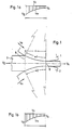
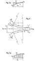
- the upper work roll 1 and the lower work roll 2 of a rolling mill are shown, between which, for example, metallic strip material is passed as the rolling stock 3.
- the length of the roll gap 4 between the two work rolls 1 and 2 is determined, on the one hand from the entry plane 5 which is normal to the direction of passage of the rolling stock 3, on the other hand from the exit plane 6 thereof which is also normal to the direction of passage of the rolling stock 3, as shown in FIGS. 1 to 5 clearly shows.
- the centering angles ⁇ 1 and a2 are indicated, which are determined by the entry plane 5 and the exit plane 6 of the rolling stock 3 to the axes of rotation of the work rolls 1 and 2, which in each case the contact surfaces of the work rolls 1 and 2 determine with the rolling stock 3 over the length of the roll gap 4.
- the centering angles a1 and a2 are each shown in the same size in FIGS. 1 to 5.
- FIGS. 1a and 1b are the Ge speed ratios, which result from the rolling process according to FIG. 1, clarified.
- the roll peripheral speed V o or V u and, on the other hand, the rolling stock speed V w - at the entry 5 of the rolling stock 3 into the roll gap 4 with V E and at the exit 6 of the rolling stock 3 from the roll gap 4 V A designated - plotted.
- the respective vertical distance between V o and V w represents the relative speed between work roll 1 or 2 and rolling stock 3.
- 1a and 1b illustrate that the circumferential speeds V o and V u of both work rolls 1 and 2 are greater than the rolling stock speed V w over the entire roll gap 4 and thus there is no flow sheath within the roll gap.
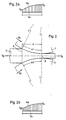
- the work rolls 1 and 2 are operated at peripheral speeds V o and V u which are lower than the rolling stock speed V w .
- the curves V w and V o and V u do not intersect (see FIGS. 2a and 2b), so that there is no flow divide here either.
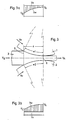
- the speed ratios for the upper work roll 1 are as explained in connection with FIG. 1, ie the peripheral speed V o of the work roll 1 is greater than the rolling stock speed V w (cf. FIG. 3a).
- the lower work roll 2 is operated according to FIG. 2 with a circumferential speed V u below the rolling stock speed V w (cf. FIG. 3b).
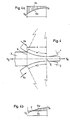
- the rolling process according to FIG. 4 corresponds to the rolling process according to FIG. 1 with regard to the speed relationships between the upper work roll 1 and the rolling stock 3 (cf. FIG. 4a).
- the lower work roll 2 and the rolling stock 3 have identical speeds in the floating separation point F, that is to say the relative speed is 0 in the floating separation point F, and the rolling stock speed V w is lower before the point F in the direction of the entry plane 5 the point F in the direction of the exit plane 6, it is greater than the circumferential roller speed V u of the lower work roll 2.
- the speed ratios in the area of the lower work roll 2 correspond to those according to FIG. 2, ie the rolling stock speed V w is always higher than the peripheral speed V u of the work roll 2.
- the speed ratios in the area of the upper work roll 1 are such that here, as in FIG. 4b forms a floating shear point F.
- the outlet speed V A of the rolling stock 3 in the exit plane 6 of the roll gap is to be lower than the peripheral speed V o , V u of the two work rolls 1 and 2, as indicated in FIG. 1, then it proves to be expedient that 6 from the infeed side of the rolling stand by determining the infeed speed V E of the rolling stock 3 either through a decoiler 7 or through a driver 8 arranged between it and the rolling stand in the form of a pair of S-rollers.
- the take-up reel 9 arranged downstream of the roll stand runs at a speed adapted to the outlet speed V A of the rolling stock 3.
- the arrangement according to FIG. 7 is also used when the method according to FIG. 3 is carried out, because here too it is necessary to work with increased forward pull. With this method, the frictional forces cancel each other out, but the horizontally acting components of the rolling forces must be compensated for by forward pulling.
- FIG. 7 An arrangement according to FIG. 7 is expediently also used to operate the method according to FIG. 5, where a flow sheath F (on the upper work roll 1) is formed.
- the pair of work rolls 1, 2 have pre-and / or post-rolled material drivers 8; 12; 14, 16 or the rolled goods reel 7, 9; 10, 11; 13, 15 are set to a drive speed that deviates from the circumferential roller speed or must be adjustable.
- the speed ratio required for the respective rolling process between the circumferential roll speed and the drive speed for the driver or reel can be determined on the basis of a speed which is fixed for the work rolls 1 and 2.
- a speed which is fixed for the work rolls 1 and 2. By a between the drive for the work rolls 1 and 2- and the drive for the drivers 8; 12; 14, 16 and / or the drives for the reel 7, 9; 10, 11; 13, 15 provided (electronic) control and / or regulating devices, the rolling stock inlet and the rolling stock outlet speeds can then be preset in a ratio corresponding to the respective pass reduction.
Landscapes
- Engineering & Computer Science (AREA)
- Mechanical Engineering (AREA)
- Metal Rolling (AREA)
- Control Of Metal Rolling (AREA)
Abstract
Description
Die Erfindung betrifft ein Verfahren zum Auswalzen von metallischen Werkstoffen, insbesondere Bandmaterial, mittels mindestens je einer oberen und einer unteren Arbeitswalze, bei welchem die Walzgutgeschwindigkeit von außerhalb des Gerüstes oder der Gerüste geführt bzw. bestimmt wird.The invention relates to a method for rolling out metallic materials, in particular strip material, by means of at least one upper and one lower work roll, in which the rolling stock speed is guided or determined from outside the stand or the stands.
Ein solches Verfahren ist bereits bekannt durch die US-A-3 823 593.Such a method is already known from US-A-3 823 593.
Bei diesem bekannten Verfahren wird die Walzgutgeschwindigkeit an der Einlaufseite des Gerüstes durch die Umfangsgeschwindigkeit der einen Arbeitswalze und die Walzgutgeschwindigkeit an der Auslaufseite des Gerüstes durch die andere Arbeitswalze des Arbeitswalzenpaares geführt bzw. bestimmt, und zwar in einem Verhältnis, das entsprechend der gewünschten Reduktion des Walzgutes fest vorgegeben ist.In this known method, the rolling stock speed on the inlet side of the stand is guided or determined by the peripheral speed of one work roll and the rolling stock speed on the outlet side of the stand by the other work roll of the pair of work rolls, in a ratio that corresponds to the desired reduction of the rolling stock is fixed.
Bei den in der Praxis am weitesten verbreiteten Verfahren zum Auswalzen von metallischen Werkstoffen, insbesondere Bandmaterial, werden die beiden auf das Walzgut einwirkenden Arbeitswalzen so angetrieben, daß sie übereinstimmende Walzenumfangsgeschwindigkeiten aufweisen, also in einem Geschwindigkeitsverhältnis 1 : 1 zueinander stehen.In the most widespread methods for rolling out metallic materials, in particular strip material, the two work rolls acting on the rolling stock are driven in such a way that they have corresponding circumferential roller speeds, that is to say they have a speed ratio of 1: 1 to one another.
Diese bekannte Walzverfahren werden dabei so ausgeübt, daß die sogenannten Fließscheiden innerhalb des Walzspaltes liegen, der einlaufseitig durch eine vom Walzguteintritt und auslaufseitig durch eine vom Walzlaufaustritt bestimmte Normalebene zum Walzgutdurchlauf begrenzt wird.These known rolling processes are carried out in such a way that the so-called flow separators lie within the roll gap, which is delimited on the inlet side by a normal plane for the rolling stock passage determined by the rolling stock inlet and on the outlet side by a normal plane determined by the rolling barrel outlet.
Durch diese Fließscheiden wird dabei im Walzspalt ein Synchronpunkt bestimmt, an welchem eine Relativgeschwindigkeit zwischen dem Walzgut und dem Umfang der Arbeitswalze auftritt. Die Lage der Fließscheide im Walzspalt stellt sich entsprechend den auf das Walzgut wirkenden Kräften, bspw. dem Vor- und Rückwärtszug, der Horizontalkomponente der Walzkräfte und den Reibkräften zwischen Walzgut und Arbeitswalze ein. Solange sich eine Fließscheide im Bereich des Walzspaltes einstellt, ist das Gerüst in der Lage, mit Hilfe der Arbeitswalzen das Walzgut zu führen, tritt jedoch keine Fließscheide im Walz- .spalt auf, so ist die Führung des Walzgutes durch die Arbeitswalzen nicht mehr möglich, weil die Durchziehreserve des Walzgerüstes erschöpft ist. Bei einem solchen Betriebszustand wird die Walzgutgeschwindigkeit nicht mehr von den Arbeitswalzen bestimmt, weil an keiner Stelle des Walzspaltes Walzenumfangsgeschwindigkeit und Walzgutgeschwindigkeit übereinstimmen.Through these flow separations, a synchronization point is determined in the roll gap at which a relative speed occurs between the rolling stock and the circumference of the work roll. The position of the flow sheath in the roll gap is adjusted in accordance with the forces acting on the rolling stock, for example the forward and backward pull, the horizontal component of the rolling forces and the frictional forces between the rolling stock and the work roll. As long as there is a flow sheath in the area of the roll gap, the stand is able to guide the rolling stock with the help of the work rolls, but if no flow sheath occurs in the roll gap, it is no longer possible to guide the rolling stock through the work rolls. because the pull-through reserve of the roll stand is exhausted. In such an operating state, the rolling stock speed is no longer determined by the work rolls, because the roller circumferential speed and the rolling stock speed do not match at any point in the roll gap.
Auch ist ein Walzen mit einer Lage der Fließscheiden in der-Nähe von Walzguteintritt oder Walzgutaustritt problematisch, weil sich schon bei geringen Änderungen der Walzbedingungen, bspw. der Bandzüge, leicht ein instabiler Zustand einstellen kann, der Schwingungserscheinungen, insbesondere Rotationsschwingungen der Arbeitswalzen, und hieraus resultierende Rutscher am Walzgut zur Folge hat.Rolling with a position of the flow edges near the rolling stock entry or exit is also problematic because an unstable condition can easily arise even with slight changes in the rolling conditions, for example the strip tension, which causes vibration phenomena, in particular rotational vibrations of the work rolls, and the like resulting slide on the rolling stock.
Beim Kaltwalzen von metallischen Werkstoffen, insbesondere Bandmaterial, ist man heute bestrebt, mit einem möglichst geringen Kraft- und Leistungsbedarf zu arbeiten. Man erreicht dies durch die Verbesserung der Schmierung und die damit erzielte Verringerung der Reibung. Hieraus ergibt sich jedoch als Nachteil zugleich eine Verringerung der Durchziehreserve der Gerüste, d. h. eine Fließscheidenlage nahe am Walzgutaustritt, bei sonst gleichen Walzbedingungen hinsichtlich Arbeitswalzendurchmesser, Abnahme und Bandzug.When cold rolling metallic materials, in particular strip material, the aim today is to work with the lowest possible power and power requirements. This is achieved by improving the lubrication and reducing friction. However, this also has the disadvantage of reducing the pull-through reserve of the scaffolding, i. H. a floating edge position close to the rolled material outlet, with otherwise the same rolling conditions with regard to work roll diameter, removal and strip tension.
Da auch beim Warmwalzen von metallischen Werkstoffen, insbesondere Bandmaterial, und in den nachgeschalteten Beizanlagen besonderer Wert auf Energieeinsparungen gelegt wird, ergibt sich die Forderung, für Kaltwalzwerke größere Warmbanddicken einzusetzen und diese, besonders in den ersten Gerüsten, mit höheren Stichabnahmen zu betreiben. Eine Erhöhung der Stichabnahmen bei sonst gleichen Walzbedingungen verringern aber ebenfalls die Durchziehreserve der Gerüste.Since special emphasis is placed on energy savings when hot-rolling metallic materials, in particular strip material, and in the subsequent pickling lines, there is a need to use larger hot-strip thicknesses for cold rolling mills and to operate them with higher passes, especially in the first stands. However, an increase in the number of passes under otherwise identical rolling conditions also reduces the pull-through reserve of the stands.
Zur Vermeidung dieser Nachteile ist durch die US-A-3 823 593 ein Walzverfahren der eingangs angegebenen Gattung, das sogenannte Schubwalzverfahren, bekanntgeworden, welches sich dadurch auszeichnet, daß die jeweils paarweise zusammenwirkenden Arbeitswalzen zueinander in einem Umfangsgeschwindigkeitsverhältnis stehen, das von 1 abweicht. Hierbei wird das Umfangsgeschwindigkeitsverhältnis zwischen den paarweise zusammenwirkenden Arbeitswalzen so eingestellt, daß sich immer innerhalb des Walzspaltes zwei verschiedene Lagen der Fließscheiden für die schnellere und die langsamere Arbeitswalze ergeben.In order to avoid these disadvantages, US-A-3 823 593 has disclosed a rolling method of the type specified at the outset, the so-called push-rolling method, which is characterized in that the working rollers, which interact in pairs, are at a circumferential speed ratio which deviates from 1. In this case, the peripheral speed ratio between the work rolls interacting in pairs is set so that there are always two different positions of the flow sheaths for the faster and the slower work roll within the roll gap.
Bedingt durch die unterschiedlichen Walzenumfangsgeschwindigkeiten der beiden zusammenarbeitenden Arbeitswalzen ist es bei diesem Schubwalzverfahren jedoch notwendig, die Walzgutgeschwindigkeit von außerhalb des Gerüstes zu führen bzw. zu bestimmen. Zu diesem Zweck wirken nach dem Stand der Technik an der Einlaufseite und der Auslaufseite des Gerüstes jeweils Treiber oder Haspel auf das Walzgut ein, wobei die Antriebsgeschwindigkeit für den einlaufseitigen Walzguttreiber bzw. Walzguthaspel in einem festen Abhängigkeitsverhältnis zur einen Arbeitswalze und die Antriebsgeschwindigkeit des auslaufseitigen Walzguttreibers bzw. Walzguthaspels in einem festen Abhängigkeitsverhältnis von der anderen Arbeitswalze des Arbeitswalzenpaares steht, um dadurch die Aufrechterhaltung der beiden Fließscheiden innerhalb des Walzspaltes sicherzustellen.Due to the different roller circumferential speeds of the two working rollers working together, it is necessary with this push rolling method to guide or determine the rolling stock speed from outside the stand. For this purpose, according to the state of the art, drivers or reels act on the rolling stock on the inlet side and the outlet side of the stand, the drive speed for the inlet-side rolling stock driver or rolling stock reel in a fixed relationship to a work roll and the driving speed of the outlet-side rolling stock driver or Rolled goods reel has a fixed relationship of dependency on the other work roll of the work roll pair, in order thereby to ensure the maintenance of the two floating edges within the roll gap.
Ein durch die US-A-3 823 593 bekanntes Walzwerk zur Ausübung des eingangs angegebenen Verfahrens arbeitet mit mindestens einem Arbeitswalzenpaar sowie diesem zugeordneten Vorrichtungen zur Variation der Walzgutgeschwindigkeit relativ zur Walzenumfangsgeschwindigkeit des Arbeitswalzenpaares, wobei die Antriebsdrehzahlen der beiden Arbeitswalzen des Arbeitswalzenpaares relativ zueinander variierbar, aber während des Walzbetriebes fest vorgegeben sind, und wobei diesem Arbeitswalzenpaar ein Walzguttreiber bzw. ein Walzguthaspel vorgeordnet sind. Aufgabe der Erfindung ist es, ein Verfahren zum Auswalzen von metallischen Werkstoffen, insbesondere Bandmaterial, der gattungsgemäßen Art sowie ein Walzwerk zur Ausübung desselben anzugeben, welches unter Nutzung der aus einer besseren Schmierung und der höheren Stichabnahme beim Kaltwalzen resultierenden Vorteile jederzeit eine ausreichende Stabilität des Walzprozesses gewährleistet.A rolling mill known from US Pat. No. 3,823,593 for performing the method specified at the outset works with at least one work pair of rollers and devices associated therewith for varying the rolling stock speed relative to the circumferential circumferential speed of the pair of work rolls, the drive speeds of the two work rolls of the pair of work rolls being variable relative to one another, but fixedly specified during the rolling operation, and a rolling stock driver or a rolling stock reel being arranged upstream of this pair of work rolls. The object of the invention is to provide a method for rolling out metallic materials, in particular strip material, of the generic type and a rolling mill for exercising the same, which, taking advantage of the advantages resulting from better lubrication and the higher pass reduction during cold rolling, ensures adequate stability of the rolling process at all times guaranteed.
Die Lösung dieser Aufgabe wird dabei in verfahrenstechnischer Hinsicht durch die Kennzeichnungsmerkmale des Anspruchs 1 erreicht.In terms of process technology, this object is achieved by the characterizing features of claim 1.
Hierbei erweist es sich als vorteilhaft, daß auch bei Schwankungen der Walzparameter, nämlich der Walzgutdicke, der Züge, der Reibung oder dergleichen, innerhalb des Walzspaltes keine Fließscheide auftritt, weil sich dort nämlich nirgendwo ein Synchronpunkt zwischen der Walzgutgeschwindigkeit und der Walzenumfangsgeschwindigkeit einstellt und deshalb mit negativer Durchziehreserve gewalzt wird.Here it proves to be advantageous that even with fluctuations in the rolling parameters, namely the rolling stock thickness, the trains, the friction or the like, no flow sheath occurs within the roll gap, because there is no synchronous point anywhere between the rolling stock speed and the circumferential roll speed and therefore with negative pull-through reserve is rolled.
Erfindungsgemäß ist es im einfachsten Falle möglich, das Verfahren entweder nach den Merkmalen des Anspruchs 2 oder aber nach den Merkmalen des Anspruchs 3 durchzuführen.According to the invention, in the simplest case it is possible to carry out the method either according to the features of
Besonders bewährt hat sich jedoch eine Verfahrensart mit den Erfindungsmerkmalen nach Anspruch 4 oder 5. Selbstverständlich ist es aber auch möglich, das Verfahren nach Anspruch 6 zu betreiben, weil hierdurch das Arbeiten des Schubwalzverfahrens besonders begünstigt wird.However, a type of method with the features of the invention according to
In verfahrenstechnischer Hinsicht ist es nach der Erfindung besonders empfehlenswert, einen Sicherheitsabstand zwischen der jeweiligen Walzenumfangsgeschwindigkeit und der Walzgutgeschwindigkeit einzuhalten, der auch bei kleinen Rotationsschwingungen der Arbeitswalzen eine Fließscheidenbildung im Bereich des Walzspaltes unterbindet. Bewährt haben sich in diesem Zusammenhang die Verfahrensmerkmale des Anspruchs 7. Wie praktische Versuche ergeben haben, ist dieses Ziel schon erreichbar, wenn die Walzgutgeschwindigkeit etwa um 5 % von der jeweiligen Walzenumfangsgeschwindigkeit abweichend größer und/oder kleiner eingestellt wird.In terms of process technology, it is particularly recommended according to the invention to maintain a safety distance between the respective roller circumferential speed and the speed of the rolling stock, which prevents the formation of flowing sheaths in the area of the roll gap even with small rotational vibrations of the work rolls. In this context, the method features of claim 7 have proven successful. As practical tests have shown, this goal can be achieved if the rolling stock speed is set larger and / or smaller deviating from the respective peripheral roll speed by approximately 5%.
Wenn eine konstante Stichabnahme am Walzgut erzielt werden soll, ist es erfindungsgemäß von Vorteil, die Verfahrensmerkmale des Anspruchs 8 zu nutzen. Möglich ist es aber auch, zum Zwecke einer veränderbaren Stichabnahme am Walzgut, die Verfahrensmaßnahmen nach Anspruch 9 anzuwenden.If a constant pass reduction on the rolling stock is to be achieved, it is advantageous according to the invention to use the method features of claim 8. However, it is also possible to use the procedural measures according to claim 9 for the purpose of a variable pass inspection on the rolling stock.
Ein Walzwerk zur Ausübung des Verfahrens zeichnet sich gegenüber dem auf die US-A-3 823 593 basierenden Stand der Technik durch die Kennzeichnungsmerkmale des Anspruchs 10 aus und kann nach den Merkmalen der Ansprüche 11 bis 13 weitergebildet werden.A rolling mill for practicing the method is distinguished from the prior art based on US Pat. No. 3,823,593 by the characterizing features of
Der DE-A-2345463 ist noch ein Walzwerk als bekannt zu entnehmen, welches außer drei hintereinandergeschalteten Walzgerüsten noch je einen einlaufseitigen und einen auslaufseitigen Walzguthaspel umfaßt. Hierbei können die beiden äußeren Walzgerüste jeweils mit Umfangsgeschwindigkeiten ihrer Walzen betrieben werden, die von der durch die Umfangsgeschwindigkeit der Arbeitswalzen des mittleren Walzgerüstes bestimmten Walzgutgeschwindigkeit abweicht.From DE-A-2345463 a rolling mill is known to be known which, in addition to three rolling stands connected in series, each also has an inlet-side and an outlet-side reel. In this case, the two outer roll stands can each be operated at the peripheral speeds of their rolls, which deviate from the rolling stock speed determined by the peripheral speed of the work rolls of the middle roll stand.
Das vorbekannte Walzwerk ist jedoch nicht so ausgelegt, daß die Antriebsdrehzahlen der beiden Arbeitswalzen des mittleren Walzgerüstes relativ zueinander variierbar, aber während des Walzbetriebes fest vorgegeben sind.However, the known rolling mill is not designed so that the drive speeds of the two work rolls of the middle roll stand can be varied relative to one another, but are predefined during the rolling operation.
Es ist daher beim bekannten Walzwerk nicht möglich, die Antriebsgeschwindigkeit am vor-und/oder nachgeordneten Walzgerüst so einzustellen, daß die Relativgeschwindigkeit des Walzbandes zu den beiden Arbeitswalzen des mittleren. Walzgerüstes jeweils unterschiedlich ausfällt.It is therefore not possible in the known rolling mill to set the drive speed on the upstream and / or downstream rolling stand in such a way that the relative speed of the rolled strip to the two work rolls of the middle one. Roll stand is different in each case.
Weitere Merkmale, Einzelheiten und Vorteile der Erfindung werden nachfolgend anhand einer Zeichnung ausführlich erläutert.Further features, details and advantages of the invention are explained in detail below with reference to a drawing.
Dabei zeigen die
- Figuren 1 bis 5 in schematisch vereinfachter Darstellung verschiedene Verwirklichungsmöglichkeiten für das erfindungsgemäße Walzverfahren,
Figur 6 in schematischer Darstellung ein Walzwerk zur Ausübung des Walzverfahrens nach Fig. 1,- Figur 7 schematisch dargestellt, ein Walzwerk zur Ausübung des Walzverfahrens nach Fig. 2, 3 und 5 und
- Figur 8 in schematischer Darstellung ein Walzwerk zur Ausübung des Walzverfahrens nach Fig. 4.
- FIGS. 1 to 5, in a schematically simplified representation, different implementation options for the rolling method according to the invention,
- 6 shows a schematic representation of a rolling mill for carrying out the rolling process according to FIG. 1,
- FIG. 7 shows schematically a rolling mill for carrying out the rolling process according to FIGS. 2, 3 and 5 and
- 8 shows a schematic illustration of a rolling mill for carrying out the rolling process according to FIG. 4.
Im sämtlichen Figuren der Zeichnung sind die obere Arbeitswalze 1 und die untere Arbeitswalze 2 eines Walzwerkes dargestellt, zwischen denen als Walzgut 3 beispielsweise metallisches Bandmaterial hindurchgeführt wird. Die Länge des Walzspaltes 4 zwischen den beiden Arbeitswalzen 1 und 2 wird bestimmt, einerseits von der normal zur Durchlaufrichtung des Walzgutes 3 liegenden Eintrittsebene 5, andererseits von der'ebenfalls normal zur Durchlaufrichtung des Walzgutes 3 liegenden Austrittsebene 6 desselben, wie das aus den Fig. 1 bis 5 deutlich hervorgeht.In all the figures of the drawing, the upper work roll 1 and the
Ferner sind in den Fig. 1 bis 5 der Zeichnung die Zentrierwinkel α1 und a2 angedeutet, welche durch die Eintrittsebene 5 und die Austrittsebene 6 des Walzgutes 3 zu den Drehachsen der Arbeitswalzen 1 und 2 bestimmt werden, welche jeweils die Kontaktflächen der Arbeitswalzen 1 und 2 mit dem Walzgut 3 über die Länge des Walzspaltes 4 bestimmen.1 to 5 of the drawing, the centering angles α1 and a2 are indicated, which are determined by the
Die Zentrierwinkel a1 und a2 sind in den Fig. 1 bis 5 jeweils in gleicher Größe dargestellt.The centering angles a1 and a2 are each shown in the same size in FIGS. 1 to 5.
Zu Fig. 1 gehören die Schaubilder nach Fig. 1a und 1b. In den Fig. 1a und 1b sind die Geschwindigkeitsverhältnisse, die sich bei dem Walzverfahren nach Fig. 1 ergeben, verdeutlicht. Über der Länge des Walzspaltes 4 sind zum einen die Walzenumfangsgeschwindigkeit Vo bzw. Vu und zum anderen die Walzgutgeschwindigkeit Vw - am Eintritt 5 des Walzgutes 3 in den Walzspalt 4 mit VE und am Austritt 6 des Walzgutes 3 aus dem Walzspalt 4 mit VA bezeichnet - aufgetragen. Der jeweilige Senkrechtabstand zwischen Vo und Vw gibt die Relativgeschwindigkeit zwischen Arbeitswalze 1 bzw. 2 und Walzgut 3 wieder. Die Fig. 1a und 1b veranschaulichen, daß über den gesamten Walzspalt 4 gesehen die Umfangsgeschwindigkeiten Vo und Vu beider Arbeitswalzen 1 und 2 größer als die Walzgutgeschwindigkeit Vw sind und somit innerhalb des Walzspaltes sich keine Fließscheide einstellt.The diagrams according to FIGS. 1a and 1b belong to FIG. 1. 1a and 1b are the Ge speed ratios, which result from the rolling process according to FIG. 1, clarified. Along the length of the
Bei dem Walzverfahren nach Fig. 2 werden die Arbeitswalzen 1 und 2 mit Umfangsgeschwindigkeiten Vo und Vu betrieben, die kleiner sind als die Walzgutgeschwindigkeit Vw. Die Kurven Vw und Vo bzw. Vu schneiden sich nicht (vgl. Fig. 2a und 2b), so daß auch hier keine Fließscheide auftritt.2, the
Bei dem Walzverfahren nach Fig. 3 liegen die Geschwindigkeitsverhältnisse für die obere Arbeitswalze 1 wie im Zusammenhang mit Fig. 1 erläutert, d. h. die Umfangsgeschwindigkeit Vo der Arbeitswalze 1 ist größer als die Walzgutgeschwindigkeit Vw (vgl. Fig. 3a). Die untere Arbeitswalze 2 wird dagegen entsprechend der Fig. 2 mit einer unter der Walzgutgeschwindigkeit Vw liegenden Umfangsgeschwindigkeit Vu betrieben (vgl. Fig. 3b).3, the speed ratios for the upper work roll 1 are as explained in connection with FIG. 1, ie the peripheral speed V o of the work roll 1 is greater than the rolling stock speed V w (cf. FIG. 3a). The
Das Walzverfahren nach Fig. 4 stimmt hinsichtlich der Geschwindigkeitsverhältnisse zwischen oberer Arbeitswalze 1 und Walzgut 3 mit dem Walzverfahren nach Fig. 1 überein (vgl. 4a). Wie Fig. 4b erkennen läßt, haben dagegen die untere Arbeitswalze 2 und das Walzgut 3 im Fließscheidenpunkt F übereinstimmende Geschwindigkeiten, d. h. im Fließscheidenpunkt F ist die Relativgeschwindigkeit 0, vor dem Punkt F in Richtung auf die Eintrittsebene 5 ist die Walzgutgeschwindigkeit Vw kleiner, hinter dem Punkt F in Richtung auf die Austrittsebene 6 ist sie größer als die Walzenumfangsgeschwindigkeit Vu der unteren Arbeitswalze 2.The rolling process according to FIG. 4 corresponds to the rolling process according to FIG. 1 with regard to the speed relationships between the upper work roll 1 and the rolling stock 3 (cf. FIG. 4a). As can be seen in FIG. 4b, on the other hand, the
Bei dem Walzverfahren nach Fig. 5 treten ähnliche Mischverhältnisse wie bei dem Verfahren nach Fig. 4 auf. Die Geschwindigkeitsverhältnisse im Bereich der unteren Arbeitswalze 2 entsprechen denen nach Fig. 2, d. h. die Walzgutgeschwindigkeit Vw liegt immer höher als die Umfangsgeschwindigkeit Vu der Arbeitswalze 2. Die Geschwindigkeitsverhältnisse im Bereich der oberen Arbeitswalze 1 sind derart, daß sich hier wie bei Fig. 4b ein Fließscheidenpunkt F ausbildet.5, mixing ratios similar to those in the method according to FIG. 4 occur. The speed ratios in the area of the
Daß nach Fig. 4b der Fließscheidenpunkt F nahe der Eintrittsebene 5 und nach Fig. 5a der Fließscheidenpunkt F nahe der Austrittsebene 6 liegen, ist besonders vorteilhaft und deshalb praxisnah. Denkbar ist jedoch eine Verlagerung der Fließscheidenpunkte F innerhalb des Walzspaltes 4 in Richtung auf die Austrittsebene 6 bzw. die Eintrittsebene 5.The fact that, according to FIG. 4b, the flow separation point F is close to the
Es ist ohne weiteres klar, daß bei den in den Fig. 1 bis 3 wiedergegebenen Walzverfahren die Arbeitswalzen 1, 2 des Walzgerüstes keine Führungseigenschaften mehr für das Walzgut 3 haben und daher die Walzgutgeschwindigkeit Vw jeweils von außerhalb des Gerüstes geführt bzw. bestimmt werden muß.It is readily apparent that in the rolling processes shown in FIGS. 1 to 3, the work rolls 1, 2 of the rolling stand no longer have any guiding properties for the
Soll beispielsweise die Auslaufgeschwindigkeit VA des Walzgutes 3. in der Austrittsebene 6 des Walzspaltes kleiner sein als die Umfangsgeschwindigkeit Vo, Vu der beiden Arbeitswalzen 1 und 2, wie das in Fig. 1 angedeutet ist, dann erweist es sich als zweckmäßig, die Laufgeschwindigkeit des Walzgutes 3 gemäß Fig. 6 von der Einlaufseite des Walzgerüstes aus zu führen, indem die Einlaufgeschwindigkeit VE des Walzgutes 3 entweder durch einen Abwickelhaspel 7 oder aber einen zwischen diesem und dem Walzgerüst angeordneten Treiber 8 in Form eines S-Rollenpaares bestimmt wird. Der dem Walzgerüst nachgeordnete Aufwickelhaspel 9 läuft hingegen mit einer der Auslaufgeschwindigkeit VA des Walzgutes 3 angepaßten Drehzahl.For example, if the outlet speed V A of the rolling
Sollen gemäß Fig. 2 die Umfangsgeschwindigkeiten Vo und Vu der Arbeitswalzen 1 und 2 kleiner als die Laufgeschwindigkeit des Walzgutes 3 in der Eintrittsebene 5 des Walzspaltes 4 gehalten werden, dann ist es vorteilhaft, zur Führung des Walzgutes 3 einer Anordnung gemäß Fig. 7 einzusetzen, bei der entweder ein dem Walzgerüst nachgeordneter Aufwickelhaspel 11 oder aber ein zwischen diesem und dem Walzgerüst angeordneter, als S-Rollenpaar ausgebildeter Treiber 12 die Auslaufgeschwindigkeit VA für das Walzgut 3 bestimmt. Der Abwickelhaspel 10 läuft hier dann entsprechend der gegenüber der Umfangsgeschwindigkeit der Walzen erhöhten Walzguteinlaufgeschwindigkeit VE mit.If the circumferential speeds V o and V u of the work rolls 1 and 2 are to be kept lower than the running speed of the
. Die Anordnung nach Fig. 7 wird auch bei Ausübung des Verfahrens nach Fig. 3 eingesetzt, weil hier ebenfalls mit erhöhtem Vorwärtszug gearbeitet werden muß. Bei diesem Verfahren heben sich die Reibkräfte auf, die horizontal wirkenden Komponenten der Walzkräfte müssen jedoch durch Vorwärtszug kompensiert werden.. The arrangement according to FIG. 7 is also used when the method according to FIG. 3 is carried out, because here too it is necessary to work with increased forward pull. With this method, the frictional forces cancel each other out, but the horizontally acting components of the rolling forces must be compensated for by forward pulling.
Anhand der Fig. 1, 2, 3, 6 und 7 wurde erläutert, wie konventionelle Bendwalzverfahren unter Sicherstellung einer ausreichenden Stabilität des Walzprozesses durch Vermeidung von Fließscheidenausbildungen innerhalb des Walzspaltes so verbessert werden können, daß trotz optimaler Schmierung und damit verbundener Verringerung der Reibung ein verringerter Kraft- und Leistungsbedarf eintritt sowie erhöhte Stichabnahmen bei sonst gleichen Walzbedingungen erreichbar sind.With reference to FIGS. 1, 2, 3, 6 and 7 it was explained how conventional Bendwalzenverfahren can be improved while ensuring sufficient stability of the rolling process by avoiding the formation of floating shafts within the roll gap so that a reduced despite optimal lubrication and the associated reduction in friction Power and power requirements occur as well as increased passes can be achieved under otherwise identical rolling conditions.
Zum Betreiben des Verfahrens nach Fig. 5, wo sich eine Fließscheide F (an der oberen Arbeitswalze 1) ausbildet, wird zweckmäßigerweise ebenfalls eine Anordnung nach Fig. 7 eingesetzt.An arrangement according to FIG. 7 is expediently also used to operate the method according to FIG. 5, where a flow sheath F (on the upper work roll 1) is formed.
Bei dem Verfahren nach Fig. 4 kann es passieren, daß Horizontalkräfte auftreten, die nahezu den beim Verfahren gemäß Fig. 1 entsprechen. Aus diesem Grund empfiehlt es sich, sowohl vor als auch hinter dem Walzgerüst Treiber 14 und 16 entsprechend Fig. 8 vorzusehen.In the method according to FIG. 4 it can happen that horizontal forces occur which almost correspond to those in the method according to FIG. 1. For this reason, it is advisable to do both before and also to provide
Es wurde bereits erwähnt, daß bei den anhand der Fig. 1 bis 5 beschriebenen Walzverfahren dem Arbeitswalzenpaar 1, 2 vor- und/oder nachgeo- - rdnete Walzguttreiber 8 ; 12; 14, 16 bzw. die Walzguthaspel 7, 9 ; 10, 11 ; 13, 15 auf eine von der Walzenumfangsgeschwindigkeit abweichende Antriebsgeschwindigkeit eingestellt sind bzw. einstellbar sein müssen.It has already been mentioned that in the rolling processes described with reference to FIGS. 1 to 5, the pair of work rolls 1, 2 have pre-and / or post-rolled material drivers 8; 12; 14, 16 or the rolled goods reel 7, 9; 10, 11; 13, 15 are set to a drive speed that deviates from the circumferential roller speed or must be adjustable.
Das für den jeweiligen Walzvorgang erforderliche Geschwindigkeitsverhältnis zwischen der Walzenumfangsgeschwindigkeit und der Antriebsgeschwindigkeit für die Treiber bzw. Haspel kann dabei ausgehend von einer für die Arbeitswalzen 1 und 2 fest vorgegebenen Drehzahl bestimmt werden. Durch eine zwischen dem Antrieb für die Arbeitswalzen 1 und 2- und dem Antrieb für die Treiber 8 ; 12 ; 14,16 und/oder den Antrieben für die Haspel 7, 9 ; 10, 11 ; 13, 15 vorgesehene (elektronische) Steuer- und/oder Regelvorrichtungen können dann die Walzguteinlauf- und die Walzgutauslaufgeschwindigkeiten in einem der jeweiligen Stichabnahme entsprechenden Verhältnis zueinander fest voreingestellt werden. Möglich ist es aber auch, die (elektronische) Steuer- und/oder Regelvorrichtung so auszulegen, daß Walzguteinlauf- bzw. Auslaufgeschwindigkeit und Walzenumfangsgeschwindigkeit in gegenseitiger Abhängigkeit gesteuert und/oder geregelt werden können.The speed ratio required for the respective rolling process between the circumferential roll speed and the drive speed for the driver or reel can be determined on the basis of a speed which is fixed for the work rolls 1 and 2. By a between the drive for the work rolls 1 and 2- and the drive for the drivers 8; 12; 14, 16 and / or the drives for the reel 7, 9; 10, 11; 13, 15 provided (electronic) control and / or regulating devices, the rolling stock inlet and the rolling stock outlet speeds can then be preset in a ratio corresponding to the respective pass reduction. However, it is also possible to design the (electronic) control and / or regulating device in such a way that the rolling stock inlet or outlet speed and the roller peripheral speed can be controlled and / or regulated in a mutually dependent manner.
Bewährt hat es sich, die Walzgut- (Einlauf- und Auslauf-) geschwindigkeit um bis zu 20 % von der jeweiligen Walzenumfangsgeschwindigkeit abweichend - größer und/oder kleiner - einzustellen, wenn eine optimale Stabilität des Walzprozesses gewährleistet bleiben soll. Abweichungen von 5 bis 8 % gewährleisten jedoch schon eine ausreichende Stabilität des Walzprozesses.It has proven useful to set the rolling stock (infeed and outfeed) speed by up to 20% from the respective circumferential roller speed - larger and / or smaller - if optimum stability of the rolling process is to be guaranteed. Deviations of 5 to 8%, however, already ensure sufficient stability of the rolling process.
Claims (13)
Priority Applications (1)
| Application Number | Priority Date | Filing Date | Title |
|---|---|---|---|
| AT83107988T ATE25012T1 (en) | 1982-08-23 | 1983-08-12 | PROCESS FOR ROLLING METALLIC MATERIALS, ESPECIALLY STRIP MATERIAL, AND ROLLING MILL FOR PERFORMING THE PROCESS. |
Applications Claiming Priority (2)
| Application Number | Priority Date | Filing Date | Title |
|---|---|---|---|
| DE19823231273 DE3231273A1 (en) | 1982-08-23 | 1982-08-23 | METHOD FOR ROLLING METAL MATERIALS, IN PARTICULAR STRIP MATERIAL, AND ROLLING MILL FOR EXERCISING THE METHOD |
| DE3231273 | 1982-08-23 |
Publications (2)
| Publication Number | Publication Date |
|---|---|
| EP0102013A1 EP0102013A1 (en) | 1984-03-07 |
| EP0102013B1 true EP0102013B1 (en) | 1987-01-21 |
Family
ID=6171488
Family Applications (1)
| Application Number | Title | Priority Date | Filing Date |
|---|---|---|---|
| EP83107988A Expired EP0102013B1 (en) | 1982-08-23 | 1983-08-12 | Method of rolling off metallic materials, particularly strip material, and rolling mill for carrying out the method |
Country Status (4)
| Country | Link |
|---|---|
| EP (1) | EP0102013B1 (en) |
| JP (1) | JPS5954414A (en) |
| AT (1) | ATE25012T1 (en) |
| DE (2) | DE3231273A1 (en) |
Families Citing this family (1)
| Publication number | Priority date | Publication date | Assignee | Title |
|---|---|---|---|---|
| DE102007049062B3 (en) | 2007-10-12 | 2009-03-12 | Siemens Ag | Operating method for introducing a rolling stock into a rolling stand of a rolling mill, control device and rolling mill for rolling a strip-shaped rolling stock |
Family Cites Families (5)
| Publication number | Priority date | Publication date | Assignee | Title |
|---|---|---|---|---|
| US1618515A (en) * | 1921-05-28 | 1927-02-22 | William C Coryell | Metal working |
| BE632512A (en) * | 1962-05-18 | |||
| US3709017A (en) * | 1969-06-26 | 1973-01-09 | V Vydrin | Method of rolling metal sheet articles between the driven rolls of the roll mill |
| US3811307A (en) * | 1971-06-28 | 1974-05-21 | V Sosjurko | Method of rolling metal sheet articles |
| SE383268B (en) * | 1972-09-11 | 1976-03-08 | Morgaardshammar Ab | COMPACT KALLVALLSVERK |
-
1982
- 1982-08-23 DE DE19823231273 patent/DE3231273A1/en not_active Withdrawn
-
1983
- 1983-08-12 DE DE8383107988T patent/DE3369255D1/en not_active Expired
- 1983-08-12 AT AT83107988T patent/ATE25012T1/en not_active IP Right Cessation
- 1983-08-12 EP EP83107988A patent/EP0102013B1/en not_active Expired
- 1983-08-19 JP JP58150443A patent/JPS5954414A/en active Pending
Non-Patent Citations (1)
| Title |
|---|
| "The Rolling of Metals", vol. 1, L. R. UNDERWOOD, J. Wiley & Sons Inc., New York, 1980, page 236 2nd paragraph * |
Also Published As
| Publication number | Publication date |
|---|---|
| EP0102013A1 (en) | 1984-03-07 |
| JPS5954414A (en) | 1984-03-29 |
| ATE25012T1 (en) | 1987-02-15 |
| DE3231273A1 (en) | 1984-02-23 |
| DE3369255D1 (en) | 1987-02-26 |
Similar Documents
| Publication | Publication Date | Title |
|---|---|---|
| EP0908248A2 (en) | Device and method for influencing the frictional relationships between an upper and a lower roll of a rolling stand | |
| DE3600144A1 (en) | ARRANGEMENT FOR REMOVING TIN, FROM HOT ROLLED STEEL TAPES | |
| EP1456421A1 (en) | Method and device for controlled straightening and cooling of a wide metal strip, especially a steel strip or sheet metal, running out of a hot rolled strip rolling mill | |
| DE3012225A1 (en) | ROLLING METHOD AND ROLLING MILL FOR ROLLING METAL STRIP | |
| EP0425715B1 (en) | Strip accumulator | |
| DE3622926C2 (en) | Continuous multi-stage rolling mill | |
| EP1311354B1 (en) | Method and device for tension levelling a cold-rolled strip and regulating the degree of levelling | |
| DE2327657A1 (en) | PROCESS FOR THE CONTINUOUS PRODUCTION OF WELDED LIGHTWEIGHT BEAM PROFILES, IN PARTICULAR I- OR T-BEAMS | |
| WO2011018063A1 (en) | Method for the multi-core deburring of wires and associated device | |
| DE2808888A1 (en) | METHOD OF ROLLING METAL STRIP AND ROLLING MILL FOR CARRYING OUT THE METHOD | |
| EP1414596A2 (en) | Hot rolling installation | |
| DE60004948T2 (en) | METHOD FOR THE CONTINUOUS PRODUCTION OF A METAL STRIP | |
| EP0102013B1 (en) | Method of rolling off metallic materials, particularly strip material, and rolling mill for carrying out the method | |
| DE102004036531B4 (en) | Hot-rolling device | |
| EP0228691B1 (en) | Rolling mill for mechanical pre-de-scaling of steel band | |
| DE3121851C2 (en) | Rolling mill with several stands arranged one behind the other for the continuous rolling of billets | |
| EP0703014B1 (en) | Method for rolling hollow blocks in an Assel rolling mill | |
| EP4257259A1 (en) | Roller conveyor for a rolling mill with improved lateral guide rollers | |
| DE2659318A1 (en) | PROCESS FOR ROLLING ROUND STEEL | |
| DE3126974A1 (en) | "ROLLING METHOD AND ROLLING MILL" | |
| DE10218575A1 (en) | Machine for separating metal sheet webs has feed rollers to pair of stacked rotating rollers for upper and lower discharge | |
| EP0925850A2 (en) | Method of rolling a metal strip | |
| DE3111603A1 (en) | Method for rolling moulded profile sections | |
| EP1294502B1 (en) | Device for processing strip | |
| DE3908147A1 (en) | METHOD FOR INCREASING FRICTION BETWEEN ROLLS AND ROLLING GOODS IN A PLANETAL ROLLING MILL AND ROLL |
Legal Events
| Date | Code | Title | Description |
|---|---|---|---|
| PUAI | Public reference made under article 153(3) epc to a published international application that has entered the european phase |
Free format text: ORIGINAL CODE: 0009012 |
|
| 17P | Request for examination filed |
Effective date: 19830812 |
|
| AK | Designated contracting states |
Designated state(s): AT DE FR GB IT |
|
| GRAA | (expected) grant |
Free format text: ORIGINAL CODE: 0009210 |
|
| AK | Designated contracting states |
Kind code of ref document: B1 Designated state(s): AT DE FR GB IT |
|
| REF | Corresponds to: |
Ref document number: 25012 Country of ref document: AT Date of ref document: 19870215 Kind code of ref document: T |
|
| REF | Corresponds to: |
Ref document number: 3369255 Country of ref document: DE Date of ref document: 19870226 |
|
| ET | Fr: translation filed | ||
| ITF | It: translation for a ep patent filed | ||
| PLBE | No opposition filed within time limit |
Free format text: ORIGINAL CODE: 0009261 |
|
| STAA | Information on the status of an ep patent application or granted ep patent |
Free format text: STATUS: NO OPPOSITION FILED WITHIN TIME LIMIT |
|
| 26N | No opposition filed | ||
| PG25 | Lapsed in a contracting state [announced via postgrant information from national office to epo] |
Ref country code: GB Free format text: LAPSE BECAUSE OF NON-PAYMENT OF DUE FEES Effective date: 19880812 Ref country code: AT Effective date: 19880812 |
|
| PG25 | Lapsed in a contracting state [announced via postgrant information from national office to epo] |
Ref country code: FR Free format text: LAPSE BECAUSE OF NON-PAYMENT OF DUE FEES Effective date: 19890428 |
|
| GBPC | Gb: european patent ceased through non-payment of renewal fee | ||
| REG | Reference to a national code |
Ref country code: FR Ref legal event code: ST |
|
| PGFP | Annual fee paid to national office [announced via postgrant information from national office to epo] |
Ref country code: DE Payment date: 19911010 Year of fee payment: 9 |
|
| PG25 | Lapsed in a contracting state [announced via postgrant information from national office to epo] |
Ref country code: DE Effective date: 19930501 |