EP0102013B1 - Procédé de laminage de matériaux métalliques, particulièrement de feuillard, et laminoir pour l'exécution du procédé - Google Patents
Procédé de laminage de matériaux métalliques, particulièrement de feuillard, et laminoir pour l'exécution du procédé Download PDFInfo
- Publication number
- EP0102013B1 EP0102013B1 EP83107988A EP83107988A EP0102013B1 EP 0102013 B1 EP0102013 B1 EP 0102013B1 EP 83107988 A EP83107988 A EP 83107988A EP 83107988 A EP83107988 A EP 83107988A EP 0102013 B1 EP0102013 B1 EP 0102013B1
- Authority
- EP
- European Patent Office
- Prior art keywords
- rolled stock
- speed
- peripheral
- roll
- rolling
- Prior art date
- Legal status (The legal status is an assumption and is not a legal conclusion. Google has not performed a legal analysis and makes no representation as to the accuracy of the status listed.)
- Expired
Links
- 238000000034 method Methods 0.000 title claims abstract description 38
- 239000000463 material Substances 0.000 title claims abstract description 11
- 239000007769 metal material Substances 0.000 title claims abstract description 8
- 238000005096 rolling process Methods 0.000 title claims description 116
- 230000002093 peripheral effect Effects 0.000 claims abstract description 29
- 230000001105 regulatory effect Effects 0.000 claims description 7
- 238000011144 upstream manufacturing Methods 0.000 claims description 6
- 238000000926 separation method Methods 0.000 description 6
- 238000005097 cold rolling Methods 0.000 description 3
- 238000005461 lubrication Methods 0.000 description 3
- 230000015572 biosynthetic process Effects 0.000 description 2
- 238000005516 engineering process Methods 0.000 description 2
- 230000001419 dependent effect Effects 0.000 description 1
- 238000010586 diagram Methods 0.000 description 1
- 238000005098 hot rolling Methods 0.000 description 1
- 238000007689 inspection Methods 0.000 description 1
- 238000012423 maintenance Methods 0.000 description 1
- 238000005554 pickling Methods 0.000 description 1
- 230000001360 synchronised effect Effects 0.000 description 1
Images

Classifications
-
- B—PERFORMING OPERATIONS; TRANSPORTING
- B21—MECHANICAL METAL-WORKING WITHOUT ESSENTIALLY REMOVING MATERIAL; PUNCHING METAL
- B21B—ROLLING OF METAL
- B21B37/00—Control devices or methods specially adapted for metal-rolling mills or the work produced thereby
- B21B37/46—Roll speed or drive motor control
-
- B—PERFORMING OPERATIONS; TRANSPORTING
- B21—MECHANICAL METAL-WORKING WITHOUT ESSENTIALLY REMOVING MATERIAL; PUNCHING METAL
- B21B—ROLLING OF METAL
- B21B2275/00—Mill drive parameters
- B21B2275/02—Speed
- B21B2275/04—Roll speed
- B21B2275/05—Speed difference between top and bottom rolls
-
- B—PERFORMING OPERATIONS; TRANSPORTING
- B21—MECHANICAL METAL-WORKING WITHOUT ESSENTIALLY REMOVING MATERIAL; PUNCHING METAL
- B21B—ROLLING OF METAL
- B21B2275/00—Mill drive parameters
- B21B2275/02—Speed
- B21B2275/06—Product speed
Definitions
- the invention relates to a method for rolling out metallic materials, in particular strip material, by means of at least one upper and one lower work roll, in which the rolling stock speed is guided or determined from outside the stand or the stands.
- the rolling stock speed on the inlet side of the stand is guided or determined by the peripheral speed of one work roll and the rolling stock speed on the outlet side of the stand by the other work roll of the pair of work rolls, in a ratio that corresponds to the desired reduction of the rolling stock is fixed.
- the two work rolls acting on the rolling stock are driven in such a way that they have corresponding circumferential roller speeds, that is to say they have a speed ratio of 1: 1 to one another.
- a synchronization point is determined in the roll gap at which a relative speed occurs between the rolling stock and the circumference of the work roll.
- the position of the flow sheath in the roll gap is adjusted in accordance with the forces acting on the rolling stock, for example the forward and backward pull, the horizontal component of the rolling forces and the frictional forces between the rolling stock and the work roll.
- the stand is able to guide the rolling stock with the help of the work rolls, but if no flow sheath occurs in the roll gap, it is no longer possible to guide the rolling stock through the work rolls. because the pull-through reserve of the roll stand is exhausted. In such an operating state, the rolling stock speed is no longer determined by the work rolls, because the roller circumferential speed and the rolling stock speed do not match at any point in the roll gap.
- Rolling with a position of the flow edges near the rolling stock entry or exit is also problematic because an unstable condition can easily arise even with slight changes in the rolling conditions, for example the strip tension, which causes vibration phenomena, in particular rotational vibrations of the work rolls, and the like resulting slide on the rolling stock.
- the aim today is to work with the lowest possible power and power requirements. This is achieved by improving the lubrication and reducing friction.
- this also has the disadvantage of reducing the pull-through reserve of the scaffolding, i. H. a floating edge position close to the rolled material outlet, with otherwise the same rolling conditions with regard to work roll diameter, removal and strip tension.
- US-A-3 823 593 has disclosed a rolling method of the type specified at the outset, the so-called push-rolling method, which is characterized in that the working rollers, which interact in pairs, are at a circumferential speed ratio which deviates from 1.
- the peripheral speed ratio between the work rolls interacting in pairs is set so that there are always two different positions of the flow sheaths for the faster and the slower work roll within the roll gap.
- drivers or reels act on the rolling stock on the inlet side and the outlet side of the stand, the drive speed for the inlet-side rolling stock driver or rolling stock reel in a fixed relationship to a work roll and the driving speed of the outlet-side rolling stock driver or Rolled goods reel has a fixed relationship of dependency on the other work roll of the work roll pair, in order thereby to ensure the maintenance of the two floating edges within the roll gap.
- a rolling mill known from US Pat. No. 3,823,593 for performing the method specified at the outset works with at least one work pair of rollers and devices associated therewith for varying the rolling stock speed relative to the circumferential circumferential speed of the pair of work rolls, the drive speeds of the two work rolls of the pair of work rolls being variable relative to one another, but fixedly specified during the rolling operation, and a rolling stock driver or a rolling stock reel being arranged upstream of this pair of work rolls.
- the object of the invention is to provide a method for rolling out metallic materials, in particular strip material, of the generic type and a rolling mill for exercising the same, which, taking advantage of the advantages resulting from better lubrication and the higher pass reduction during cold rolling, ensures adequate stability of the rolling process at all times guaranteed.
- a rolling mill for practicing the method is distinguished from the prior art based on US Pat. No. 3,823,593 by the characterizing features of claim 10 and can be further developed according to the features of claims 11 to 13.
- a rolling mill which, in addition to three rolling stands connected in series, each also has an inlet-side and an outlet-side reel.
- the two outer roll stands can each be operated at the peripheral speeds of their rolls, which deviate from the rolling stock speed determined by the peripheral speed of the work rolls of the middle roll stand.
- the known rolling mill is not designed so that the drive speeds of the two work rolls of the middle roll stand can be varied relative to one another, but are predefined during the rolling operation.
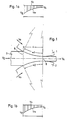
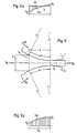
- the upper work roll 1 and the lower work roll 2 of a rolling mill are shown, between which, for example, metallic strip material is passed as the rolling stock 3.
- the length of the roll gap 4 between the two work rolls 1 and 2 is determined, on the one hand from the entry plane 5 which is normal to the direction of passage of the rolling stock 3, on the other hand from the exit plane 6 thereof which is also normal to the direction of passage of the rolling stock 3, as shown in FIGS. 1 to 5 clearly shows.
- the centering angles ⁇ 1 and a2 are indicated, which are determined by the entry plane 5 and the exit plane 6 of the rolling stock 3 to the axes of rotation of the work rolls 1 and 2, which in each case the contact surfaces of the work rolls 1 and 2 determine with the rolling stock 3 over the length of the roll gap 4.
- the centering angles a1 and a2 are each shown in the same size in FIGS. 1 to 5.
- FIGS. 1a and 1b are the Ge speed ratios, which result from the rolling process according to FIG. 1, clarified.
- the roll peripheral speed V o or V u and, on the other hand, the rolling stock speed V w - at the entry 5 of the rolling stock 3 into the roll gap 4 with V E and at the exit 6 of the rolling stock 3 from the roll gap 4 V A designated - plotted.
- the respective vertical distance between V o and V w represents the relative speed between work roll 1 or 2 and rolling stock 3.
- 1a and 1b illustrate that the circumferential speeds V o and V u of both work rolls 1 and 2 are greater than the rolling stock speed V w over the entire roll gap 4 and thus there is no flow sheath within the roll gap.
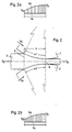
- the work rolls 1 and 2 are operated at peripheral speeds V o and V u which are lower than the rolling stock speed V w .
- the curves V w and V o and V u do not intersect (see FIGS. 2a and 2b), so that there is no flow divide here either.
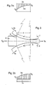
- the speed ratios for the upper work roll 1 are as explained in connection with FIG. 1, ie the peripheral speed V o of the work roll 1 is greater than the rolling stock speed V w (cf. FIG. 3a).
- the lower work roll 2 is operated according to FIG. 2 with a circumferential speed V u below the rolling stock speed V w (cf. FIG. 3b).
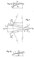
- the rolling process according to FIG. 4 corresponds to the rolling process according to FIG. 1 with regard to the speed relationships between the upper work roll 1 and the rolling stock 3 (cf. FIG. 4a).
- the lower work roll 2 and the rolling stock 3 have identical speeds in the floating separation point F, that is to say the relative speed is 0 in the floating separation point F, and the rolling stock speed V w is lower before the point F in the direction of the entry plane 5 the point F in the direction of the exit plane 6, it is greater than the circumferential roller speed V u of the lower work roll 2.
- the speed ratios in the area of the lower work roll 2 correspond to those according to FIG. 2, ie the rolling stock speed V w is always higher than the peripheral speed V u of the work roll 2.
- the speed ratios in the area of the upper work roll 1 are such that here, as in FIG. 4b forms a floating shear point F.
- the outlet speed V A of the rolling stock 3 in the exit plane 6 of the roll gap is to be lower than the peripheral speed V o , V u of the two work rolls 1 and 2, as indicated in FIG. 1, then it proves to be expedient that 6 from the infeed side of the rolling stand by determining the infeed speed V E of the rolling stock 3 either through a decoiler 7 or through a driver 8 arranged between it and the rolling stand in the form of a pair of S-rollers.
- the take-up reel 9 arranged downstream of the roll stand runs at a speed adapted to the outlet speed V A of the rolling stock 3.
- the arrangement according to FIG. 7 is also used when the method according to FIG. 3 is carried out, because here too it is necessary to work with increased forward pull. With this method, the frictional forces cancel each other out, but the horizontally acting components of the rolling forces must be compensated for by forward pulling.
- FIG. 7 An arrangement according to FIG. 7 is expediently also used to operate the method according to FIG. 5, where a flow sheath F (on the upper work roll 1) is formed.
- the pair of work rolls 1, 2 have pre-and / or post-rolled material drivers 8; 12; 14, 16 or the rolled goods reel 7, 9; 10, 11; 13, 15 are set to a drive speed that deviates from the circumferential roller speed or must be adjustable.
- the speed ratio required for the respective rolling process between the circumferential roll speed and the drive speed for the driver or reel can be determined on the basis of a speed which is fixed for the work rolls 1 and 2.
- a speed which is fixed for the work rolls 1 and 2. By a between the drive for the work rolls 1 and 2- and the drive for the drivers 8; 12; 14, 16 and / or the drives for the reel 7, 9; 10, 11; 13, 15 provided (electronic) control and / or regulating devices, the rolling stock inlet and the rolling stock outlet speeds can then be preset in a ratio corresponding to the respective pass reduction.
Landscapes
- Engineering & Computer Science (AREA)
- Mechanical Engineering (AREA)
- Metal Rolling (AREA)
- Control Of Metal Rolling (AREA)
Claims (13)
Priority Applications (1)
| Application Number | Priority Date | Filing Date | Title |
|---|---|---|---|
| AT83107988T ATE25012T1 (de) | 1982-08-23 | 1983-08-12 | Verfahren zum auswalzen von metallischen werkstoffen, insbesondere bandmaterial, und walzwerk zur ausuebung des verfahrens. |
Applications Claiming Priority (2)
| Application Number | Priority Date | Filing Date | Title |
|---|---|---|---|
| DE19823231273 DE3231273A1 (de) | 1982-08-23 | 1982-08-23 | Verfahren zum auswalzen von metallischen werkstoffen, insbesondere bandmaterial, und walzwerk zur ausuebung des verfahrens |
| DE3231273 | 1982-08-23 |
Publications (2)
| Publication Number | Publication Date |
|---|---|
| EP0102013A1 EP0102013A1 (fr) | 1984-03-07 |
| EP0102013B1 true EP0102013B1 (fr) | 1987-01-21 |
Family
ID=6171488
Family Applications (1)
| Application Number | Title | Priority Date | Filing Date |
|---|---|---|---|
| EP83107988A Expired EP0102013B1 (fr) | 1982-08-23 | 1983-08-12 | Procédé de laminage de matériaux métalliques, particulièrement de feuillard, et laminoir pour l'exécution du procédé |
Country Status (4)
| Country | Link |
|---|---|
| EP (1) | EP0102013B1 (fr) |
| JP (1) | JPS5954414A (fr) |
| AT (1) | ATE25012T1 (fr) |
| DE (2) | DE3231273A1 (fr) |
Families Citing this family (1)
| Publication number | Priority date | Publication date | Assignee | Title |
|---|---|---|---|---|
| DE102007049062B3 (de) | 2007-10-12 | 2009-03-12 | Siemens Ag | Betriebsverfahren zum Einbringen eines Walzguts in ein Walzgerüst eines Walzwerks, Steuereinrichtung und Walzwerk zum Walzen eines bandförmigen Walzgutes |
Family Cites Families (5)
| Publication number | Priority date | Publication date | Assignee | Title |
|---|---|---|---|---|
| US1618515A (en) * | 1921-05-28 | 1927-02-22 | William C Coryell | Metal working |
| BE632512A (fr) * | 1962-05-18 | |||
| US3709017A (en) * | 1969-06-26 | 1973-01-09 | V Vydrin | Method of rolling metal sheet articles between the driven rolls of the roll mill |
| US3811307A (en) * | 1971-06-28 | 1974-05-21 | V Sosjurko | Method of rolling metal sheet articles |
| SE383268B (sv) * | 1972-09-11 | 1976-03-08 | Morgaardshammar Ab | Kompakt kallvallsverk |
-
1982
- 1982-08-23 DE DE19823231273 patent/DE3231273A1/de not_active Withdrawn
-
1983
- 1983-08-12 DE DE8383107988T patent/DE3369255D1/de not_active Expired
- 1983-08-12 AT AT83107988T patent/ATE25012T1/de not_active IP Right Cessation
- 1983-08-12 EP EP83107988A patent/EP0102013B1/fr not_active Expired
- 1983-08-19 JP JP58150443A patent/JPS5954414A/ja active Pending
Non-Patent Citations (1)
| Title |
|---|
| "The Rolling of Metals", vol. 1, L. R. UNDERWOOD, J. Wiley & Sons Inc., New York, 1980, page 236 2nd paragraph * |
Also Published As
| Publication number | Publication date |
|---|---|
| EP0102013A1 (fr) | 1984-03-07 |
| JPS5954414A (ja) | 1984-03-29 |
| ATE25012T1 (de) | 1987-02-15 |
| DE3231273A1 (de) | 1984-02-23 |
| DE3369255D1 (en) | 1987-02-26 |
Similar Documents
| Publication | Publication Date | Title |
|---|---|---|
| EP0908248A2 (fr) | Dispositif et procédé pour influencer les conditions de friction entre un cylindre supérieur et un cylindre inférieur d'une cage de laminoir | |
| DE3600144A1 (de) | Anordnung zum entfernen von zunder von warmgewalzten stahlbaendern | |
| EP1456421A1 (fr) | Procede et dispositif pour dresser et refroidir de maniere regulee un feuillard metallique large, notamment un feuillard d'acier ou une tole, sortant d'un laminoir a chaud pour feuillards | |
| DE3012225A1 (de) | Walzverfahren und walzwerk zum walzen von metallband | |
| EP0425715B1 (fr) | Accumulateur de bandes | |
| DE3622926C2 (de) | Kontinuierliches mehrstufiges Walzwerk | |
| EP1311354B1 (fr) | Procede et dispositif de dressage par etirage de feuillards lamines a froid et reglage du degre d'etirage | |
| DE2327657A1 (de) | Verfahren zum kontinuierlichen herstellen von geschweissten leichtbautraegerprofilen, insbesondere i- oder ttraegern | |
| WO2011018063A1 (fr) | Procédé pour l'ébavurage multibrin de brins de fil et dispositif correspondant | |
| DE2808888A1 (de) | Verfahren zum walzen von metallbaendern und walzwerk zur durchfuehrung des verfahrens | |
| EP1414596A2 (fr) | Installation de laminage a chaud | |
| DE60004948T2 (de) | Verfahren zur kontinuierlichen herstellung eines metallbandes | |
| EP0102013B1 (fr) | Procédé de laminage de matériaux métalliques, particulièrement de feuillard, et laminoir pour l'exécution du procédé | |
| DE102004036531B4 (de) | Warmwalzvorrichtung | |
| EP0228691B1 (fr) | Laminoir pour prédécalaminage mécanique de feuillard d'acier | |
| DE3121851C2 (de) | Walzanlage mit mehreren, hintereinander angeordneten Gerüsten zum kontinuierlichen Walzen von Knüppeln | |
| EP0703014B1 (fr) | Procédé pour laminer des blocs creux dans un laminoir de type Assel | |
| EP4257259A1 (fr) | Train de rouleaux d'un laminoir pourvu de rouleaux de guidage latéraux améliorés | |
| DE2659318A1 (de) | Verfahren zum walzen von rundstahl | |
| DE3126974A1 (de) | "walzverfahren und walzwerk" | |
| DE10218575A1 (de) | Trennvorrichtung für bandförmiges Halbzeug mit Sollbruchstellen | |
| EP0925850A2 (fr) | Procédé de laminage pour une bande métallique | |
| DE3111603A1 (de) | Verfahren zum walzen von formprofilen | |
| EP1294502B1 (fr) | Dispositif de traitement de bande | |
| DE3908147A1 (de) | Verfahren zum erhoehen der reibung zwischen walzen und walzgut in einem planetenwalzwerk sowie walze |
Legal Events
| Date | Code | Title | Description |
|---|---|---|---|
| PUAI | Public reference made under article 153(3) epc to a published international application that has entered the european phase |
Free format text: ORIGINAL CODE: 0009012 |
|
| 17P | Request for examination filed |
Effective date: 19830812 |
|
| AK | Designated contracting states |
Designated state(s): AT DE FR GB IT |
|
| GRAA | (expected) grant |
Free format text: ORIGINAL CODE: 0009210 |
|
| AK | Designated contracting states |
Kind code of ref document: B1 Designated state(s): AT DE FR GB IT |
|
| REF | Corresponds to: |
Ref document number: 25012 Country of ref document: AT Date of ref document: 19870215 Kind code of ref document: T |
|
| REF | Corresponds to: |
Ref document number: 3369255 Country of ref document: DE Date of ref document: 19870226 |
|
| ET | Fr: translation filed | ||
| ITF | It: translation for a ep patent filed | ||
| PLBE | No opposition filed within time limit |
Free format text: ORIGINAL CODE: 0009261 |
|
| STAA | Information on the status of an ep patent application or granted ep patent |
Free format text: STATUS: NO OPPOSITION FILED WITHIN TIME LIMIT |
|
| 26N | No opposition filed | ||
| PG25 | Lapsed in a contracting state [announced via postgrant information from national office to epo] |
Ref country code: GB Free format text: LAPSE BECAUSE OF NON-PAYMENT OF DUE FEES Effective date: 19880812 Ref country code: AT Effective date: 19880812 |
|
| PG25 | Lapsed in a contracting state [announced via postgrant information from national office to epo] |
Ref country code: FR Free format text: LAPSE BECAUSE OF NON-PAYMENT OF DUE FEES Effective date: 19890428 |
|
| GBPC | Gb: european patent ceased through non-payment of renewal fee | ||
| REG | Reference to a national code |
Ref country code: FR Ref legal event code: ST |
|
| PGFP | Annual fee paid to national office [announced via postgrant information from national office to epo] |
Ref country code: DE Payment date: 19911010 Year of fee payment: 9 |
|
| PG25 | Lapsed in a contracting state [announced via postgrant information from national office to epo] |
Ref country code: DE Effective date: 19930501 |