EP0102022A2 - Dispositif pour tendre une bande de papier d'impression dans une imprimante - Google Patents
Dispositif pour tendre une bande de papier d'impression dans une imprimante Download PDFInfo
- Publication number
- EP0102022A2 EP0102022A2 EP83108042A EP83108042A EP0102022A2 EP 0102022 A2 EP0102022 A2 EP 0102022A2 EP 83108042 A EP83108042 A EP 83108042A EP 83108042 A EP83108042 A EP 83108042A EP 0102022 A2 EP0102022 A2 EP 0102022A2
- Authority
- EP
- European Patent Office
- Prior art keywords
- printing
- printing form
- platen
- printer
- stretching
- Prior art date
- Legal status (The legal status is an assumption and is not a legal conclusion. Google has not performed a legal analysis and makes no representation as to the accuracy of the status listed.)
- Withdrawn
Links
Images
Classifications
-
- B—PERFORMING OPERATIONS; TRANSPORTING
- B41—PRINTING; LINING MACHINES; TYPEWRITERS; STAMPS
- B41J—TYPEWRITERS; SELECTIVE PRINTING MECHANISMS, i.e. MECHANISMS PRINTING OTHERWISE THAN FROM A FORME; CORRECTION OF TYPOGRAPHICAL ERRORS
- B41J15/00—Devices or arrangements of selective printing mechanisms, e.g. ink-jet printers or thermal printers, specially adapted for supporting or handling copy material in continuous form, e.g. webs
- B41J15/16—Means for tensioning or winding the web
Definitions
- the present invention relates to a printing form stretching device in a printer.
- the prin ting form has to be suitably stretched and steadly positioned in order to obtain a high printing quality.
- the printing is generally obtained by means of printing elements moving as to the printing form, as for instance type-bearing drums or belts in case of so-called parallel printers and printing heads movable along the printing line in case of so-called serial prin ters.
- the movement of the printing element as to the printing form causes some form displacements which may be avoided only by a suitable stret ching of the printing form.
- the printing form stretching is only provided along the form feed direction(that is the direction transversal to the prin ting line) by means of feeding devices such as pin tractors, pin wheels, friction feeding rollers.
- the device object of the present invention overcomes such inconvenient and secures a suitable stretching of the printing form along the longi tudinal direction.
- the device of the present invention achieves the longitudinal stretching of the form by means of elastical pressure rollers mounted on one or more supporting bars.
- One or more pressure rollers arranged next to the central zone of the printing form and of conventional cylindrical shape, press the form against the printer platen.
- One or more pressure rollers arranged next to each of the printing form edges and of conical shape, besides pressing the form against the platen, apply on the form edges some longitudinal forces which stretch the form so assuring both a suitable longitudinal stretching along the printing line and a perfect contact with the platen.
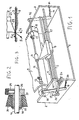
- perspective Figure 1 shows schematically a simplified view of a printer provided with the printing form stretching device of the invention.
- FIG 1 only shows the printer elementsessential for the invention understanding.
- the printer comprises a frame, a printing mechanism and a paper feeding mechanism.
- the frame is for instance constituted by a base 1 and two sides 2, 3.
- the printing mechanism is constituted by two guiding bars 4, 5 mounted between the sides and on which a printing carriage 6 slides.
- a printing head 7 is mounted on a printing carriage 6.
- Head 7 may be for instance of needle type; in such case the printing of the several characters is obtained with dot composition through the selective excitation of the several head needles and the transversal movement of the head and of the carriage.
- the printing is performed on printing form 9 which partially winds round platen 8.
- Platen 8 is mounted on a shaft 10 constrained to sides 2, 3.
- Platen 8 may act as feeding element of the printing form.
- the printer may be provided with a form feed mechanism constituted by pin tractors operated by a suitable motor.
- the paper feeding device of the invention comprises some pressure ele. ments 11, 12, 13 mounted on a bar 14 on which they may rotate.
- Such elements are resilient (preferably of rubber with high friction coefficient) and press printing form 9 against platen 8.
- Bar 14 parallel to printing platen 8, is arranged next to the printing line (preferably, but not necessarily, downstream such line). Bar 14 is substained, at its ends, by two control levers 15, 16 which may rotate on a lever anchor bar 17 pivoted on sides 2, 3.
- Such arms owing to the rotation of bar 17, allow to move elements 11, 12, 13 away from platen 8.
- the pressure and stretching resi lient elements 11, 12, 13 are suitably shaped.
- element 11 is cylindrical and is arranged next to the central part of bar 14; on the contrary elements 12, 13 are truncated cone-shaped and are arranged next to the ends of bar 14 with their tapers turned towards element 11.
- Figure 2 shows the cross section of pressure element 12.
- Pressure element 13 is identical.
- Element 12 is constituted by a coupling 25, engaged on bar 14 and pro vided with a cylindrical shoulder 2 6 , and by a cylindrical bushing 27 on which a resilient roller 28, preferably of rubber and with cone-shaped external surface, is engaged.
- Cylindrical shoulder 26 has a radial threaded opening where a locking screw 29, provided with knurled head, is screwed.
- Bushing 27 is engaged on coupling 25 on which it is free to rotate.
- the axial movements of bushing 27 (and therefore of conical roller .28) along the coupling are prevented on a side by shoulder 26 and on the other side by a ring or collar 30 housed into a coupling groove.
- Coupling 25 may be locked on bar 14 in a preestablished axial position by means of locking screw 29.
- the pressure rollers may be axially moved so as to be arranged next to the printing form edges whatever the printing support width is.
- Component F tangential to the platen surface, pulls printing form 9 towards its direction.
- bar 14 instead to be steadly fixed to arms 15, 16, will be pivoted on these ones and will be coupled to suitable driving geara
- the axial restraint of elements 11, 12, 13 will be preferably obtained with means different from the locking screw, for instance with collect chucks coaxial to bar 14 and provided with locking knurled collar.
- the lever mechanism which allows to move bar 14 and elements 11, 12, 13 away from the platen is merely explanatory and may be substituted with any spring or cam bistable mechanism or with levers of different type.
- the printer is designed to print on fixed width forms, the free axial positioning of the cone-shaped elements on bar 14 is not necessary.
Landscapes
- Handling Of Sheets (AREA)
- Registering, Tensioning, Guiding Webs, And Rollers Therefor (AREA)
- Advancing Webs (AREA)
Applications Claiming Priority (2)
| Application Number | Priority Date | Filing Date | Title |
|---|---|---|---|
| IT2302482 | 1982-08-30 | ||
| IT23024/82A IT1153720B (it) | 1982-08-30 | 1982-08-30 | Dispositivo di tensionamento del modulo di stampa in una stampante |
Publications (2)
| Publication Number | Publication Date |
|---|---|
| EP0102022A2 true EP0102022A2 (fr) | 1984-03-07 |
| EP0102022A3 EP0102022A3 (fr) | 1985-07-03 |
Family
ID=11203008
Family Applications (1)
| Application Number | Title | Priority Date | Filing Date |
|---|---|---|---|
| EP83108042A Withdrawn EP0102022A3 (fr) | 1982-08-30 | 1983-08-13 | Dispositif pour tendre une bande de papier d'impression dans une imprimante |
Country Status (4)
| Country | Link |
|---|---|
| EP (1) | EP0102022A3 (fr) |
| AU (1) | AU1845183A (fr) |
| BR (1) | BR8304647A (fr) |
| IT (1) | IT1153720B (fr) |
Cited By (1)
| Publication number | Priority date | Publication date | Assignee | Title |
|---|---|---|---|---|
| EP0184263A1 (fr) * | 1984-12-07 | 1986-06-11 | Koninklijke Philips Electronics N.V. | Dispositif pour le transport d'une bande souple |
Families Citing this family (1)
| Publication number | Priority date | Publication date | Assignee | Title |
|---|---|---|---|---|
| CN116155059B (zh) * | 2022-12-22 | 2023-11-17 | 浙江宝纺印染有限公司 | 一种仿蜡染印花用摩擦磁电微能源收集装置 |
Family Cites Families (2)
| Publication number | Priority date | Publication date | Assignee | Title |
|---|---|---|---|---|
| US3929327A (en) * | 1974-04-01 | 1975-12-30 | Addressograph Multigraph | Document transport and registration apparatus |
| DE2847577A1 (de) * | 1978-11-02 | 1980-05-08 | Olympia Werke Ag | Tintenschreib-, druck-, kopierwerk mit andruckrollen auf drehbar gelagerter antriebswelle |
-
1982
- 1982-08-30 IT IT23024/82A patent/IT1153720B/it active
-
1983
- 1983-08-13 EP EP83108042A patent/EP0102022A3/fr not_active Withdrawn
- 1983-08-26 BR BR8304647A patent/BR8304647A/pt unknown
- 1983-08-26 AU AU18451/83A patent/AU1845183A/en not_active Abandoned
Cited By (2)
| Publication number | Priority date | Publication date | Assignee | Title |
|---|---|---|---|---|
| EP0184263A1 (fr) * | 1984-12-07 | 1986-06-11 | Koninklijke Philips Electronics N.V. | Dispositif pour le transport d'une bande souple |
| US4629177A (en) * | 1984-12-07 | 1986-12-16 | U.S. Philips Corporation | Pressure roller arrangement for a paper transport device |
Also Published As
| Publication number | Publication date |
|---|---|
| IT8223024A1 (it) | 1984-03-01 |
| AU1845183A (en) | 1984-03-08 |
| EP0102022A3 (fr) | 1985-07-03 |
| IT8223024A0 (it) | 1982-08-30 |
| IT1153720B (it) | 1987-01-14 |
| BR8304647A (pt) | 1984-04-10 |
Similar Documents
| Publication | Publication Date | Title |
|---|---|---|
| EP0360728B1 (fr) | Dispositif pour régler l'espacement entre la tête d'impression et le cylindre d'une imprimante, notamment d'une imprimante à aiguilles | |
| EP0042921A1 (fr) | Ruban entourant une tête d'imprimante pour un mécanisme d'imprimante | |
| EP0102022A2 (fr) | Dispositif pour tendre une bande de papier d'impression dans une imprimante | |
| US4160606A (en) | Paper feed mechanism for multiple copy printer | |
| CA1037508A (fr) | Dispositif d'alimentation en papier | |
| EP0517285B1 (fr) | Alimentation des feuilles apte pour l'utilisation dans les imprimantes en série | |
| US3568812A (en) | Holdback devices | |
| JPS5829748B2 (ja) | キャリッジ上に交換可能なタイプボデ−を備えたタイプライタ− | |
| GB2163705A (en) | Paper feeder for printers | |
| US4475825A (en) | Non-impact printing apparatus | |
| US4514101A (en) | Paper thickness adjusting mechanism for impact printer | |
| US4448554A (en) | Sheet feeding apparatus having an expansible periphery | |
| US4623275A (en) | Shifting mechanism for a sintered-body platen in a dot-matrix impact printer | |
| US4527921A (en) | Paper feed apparatus for shuttle printer | |
| US3250366A (en) | Apparatus for equalizing the impacts of types in the lower case and upper case positions | |
| JP3475561B2 (ja) | 小型プリンタ | |
| JPS59222373A (ja) | 印字装置 | |
| US3752290A (en) | Advanced mechanism for inked ribbons or the like | |
| US5597251A (en) | Color printer | |
| US3145822A (en) | Tape actuated movable mechanical writing head | |
| EP0056955A2 (fr) | Procédé d'alimentation en papier dans des imprimantes | |
| EP0165396A3 (fr) | Cassette à ruban encreur pour imprimante | |
| JPS5649292A (en) | Serial printer | |
| JPS5872491A (ja) | 印字圧調整機構 | |
| JPH078221Y2 (ja) | プリンタのプラテン機構 |
Legal Events
| Date | Code | Title | Description |
|---|---|---|---|
| PUAI | Public reference made under article 153(3) epc to a published international application that has entered the european phase |
Free format text: ORIGINAL CODE: 0009012 |
|
| AK | Designated contracting states |
Designated state(s): CH DE FR GB LI NL |
|
| PUAL | Search report despatched |
Free format text: ORIGINAL CODE: 0009013 |
|
| AK | Designated contracting states |
Designated state(s): CH DE FR GB LI NL |
|
| STAA | Information on the status of an ep patent application or granted ep patent |
Free format text: STATUS: THE APPLICATION IS DEEMED TO BE WITHDRAWN |
|
| 18D | Application deemed to be withdrawn |
Effective date: 19860303 |
|
| RIN1 | Information on inventor provided before grant (corrected) |
Inventor name: PAGLIARO, VITTORIO |