EP0102063A2 - Schussfadeneinsetzvorrichtung für Düsenwebmaschinen und mit dieser Vorrichtung ausgerüstete Webmaschine - Google Patents
Schussfadeneinsetzvorrichtung für Düsenwebmaschinen und mit dieser Vorrichtung ausgerüstete Webmaschine Download PDFInfo
- Publication number
- EP0102063A2 EP0102063A2 EP83108381A EP83108381A EP0102063A2 EP 0102063 A2 EP0102063 A2 EP 0102063A2 EP 83108381 A EP83108381 A EP 83108381A EP 83108381 A EP83108381 A EP 83108381A EP 0102063 A2 EP0102063 A2 EP 0102063A2
- Authority
- EP
- European Patent Office
- Prior art keywords
- weft inserting
- weft
- lever
- loom
- inserting device
- Prior art date
- Legal status (The legal status is an assumption and is not a legal conclusion. Google has not performed a legal analysis and makes no representation as to the accuracy of the status listed.)
- Granted
Links
- 230000005540 biological transmission Effects 0.000 claims abstract description 22
- 230000033001 locomotion Effects 0.000 abstract description 7
- 239000012530 fluid Substances 0.000 description 3
- 238000003780 insertion Methods 0.000 description 2
- 230000037431 insertion Effects 0.000 description 2
- 238000012986 modification Methods 0.000 description 1
- 230000004048 modification Effects 0.000 description 1
- 230000000153 supplemental effect Effects 0.000 description 1
Images


Classifications
-
- D—TEXTILES; PAPER
- D03—WEAVING
- D03D—WOVEN FABRICS; METHODS OF WEAVING; LOOMS
- D03D47/00—Looms in which bulk supply of weft does not pass through shed, e.g. shuttleless looms, gripper shuttle looms, dummy shuttle looms
- D03D47/28—Looms in which bulk supply of weft does not pass through shed, e.g. shuttleless looms, gripper shuttle looms, dummy shuttle looms wherein the weft itself is projected into the shed
-
- D—TEXTILES; PAPER
- D03—WEAVING
- D03D—WOVEN FABRICS; METHODS OF WEAVING; LOOMS
- D03D47/00—Looms in which bulk supply of weft does not pass through shed, e.g. shuttleless looms, gripper shuttle looms, dummy shuttle looms
- D03D47/28—Looms in which bulk supply of weft does not pass through shed, e.g. shuttleless looms, gripper shuttle looms, dummy shuttle looms wherein the weft itself is projected into the shed
- D03D47/30—Looms in which bulk supply of weft does not pass through shed, e.g. shuttleless looms, gripper shuttle looms, dummy shuttle looms wherein the weft itself is projected into the shed by gas jet
- D03D47/3006—Construction of the nozzles
- D03D47/3013—Main nozzles
-
- D—TEXTILES; PAPER
- D03—WEAVING
- D03D—WOVEN FABRICS; METHODS OF WEAVING; LOOMS
- D03D47/00—Looms in which bulk supply of weft does not pass through shed, e.g. shuttleless looms, gripper shuttle looms, dummy shuttle looms
- D03D47/28—Looms in which bulk supply of weft does not pass through shed, e.g. shuttleless looms, gripper shuttle looms, dummy shuttle looms wherein the weft itself is projected into the shed
- D03D47/30—Looms in which bulk supply of weft does not pass through shed, e.g. shuttleless looms, gripper shuttle looms, dummy shuttle looms wherein the weft itself is projected into the shed by gas jet
- D03D47/3026—Air supply systems
- D03D47/3033—Controlling the air supply
- D03D47/3046—Weft yarn selection
Definitions
- This invention relates to a loom such as a jet loom and to a weft inserting device, e.g. for a jet loom such as the type in which a plurality of main nozzles adapted for inserting weft yarns are associated with respective supply units supplying said weft yarns.
- the weft inserting device of the present invention reciprocating motion of a driving member of the jet loom is transmitted to a main nozzle change lever in accordance with a weft yarn selection program.
- the driving member is a cam lever that is swung in reciprocation with rotation of the cam plate. The swinging . movement of the cam lever is transmitted to the change lever carrying a pair of main nozzles in accordance with preset weft yarn selecting program.
- Desired ones of the main nozzles may be used selectively and in different ways by properly formulating the program and without the necessity of changing mechanical design.
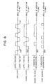
- Figs. 1 to 6 illustrate an embodiment of the present invention when applied to a weft inserting device mounted to a frame side of a loom.
- the numeral 1 designates a cam plate secured to a driving shaft 2 and making a half revolution per each revolution of movable loom parts, not shown.
- the numeral 3 designates a cam lever or driving member adapted for making a reciprocating swinging motion about pin 4 with rotation of cam plate 1.
- the cam lever 3 has a portion 3a carrying a first solenoid 5 and a latch rod 6 projecting from the surface of the lever portion 3a upon energization of the solenoid 5.
- the cam lever 3 also has another portion 3b carrying a cam follower 3c which is continuously urged by a spring 7 clockwise in Fig.
- the numeral 8 designates a transmission lever mounted for rotation about pin 4 and urged by a spring 9 to rotate clockwise so that it may engage at the lower edge thereof with the latch rod 6.
- the numeral 10 desigates a stop of the lever 3.
- the numeral 11 designates a change lever or a main nozzle supporting member mounted for swinging about a pin 13 and in the neighborhood of the weft inserting position and biased by a spring 12 to rotate clockwise in Fig. 2.
- This change lever 11 has a first lever portion lla connected by a connecting bar 14 to the transmission lever 8, a second lever portion llb carrying a first main nozzle 15 adapted for inserting weft yarn Yl supplied from a weft yarn supply unit, not shown, and a second lever portion llc carrying a second main nozzle 16 adapted for inserting weft yarn Y2 supplied from another weft yarn supply, also not shown.
- the numeral 17 designates a second solenoid adapted to be energized when the second main nozzle 16 has been shifted to the weft inserting position as shown in Fig. 4. With energization of the second solenoid 17, a holding rod 18 operatively associated therewith is extended to a position engageable with the lower edge of the first lever portion lla.
- the numeral 19 designates a control unit, such as a microcomputer, for supplying command signals the solenoids 5, 17 in accordance with a weft selection program which may be stored e.g. in a ROM.
- fluid supply valve means for controlling the fluid supplied to the first and second main nozzles 15, 16 are operated in response to the movement of the holding rod 18 in such a manner that the fluid is supplied to the second main nozzle 16 or to the first main nozzle 15 depending on whether the holding rod 18 has or has not been extended into the position engaging with the lower edge of the first lever portion lla.
- cam lever 3 is rotated counterclockwise in Fig. 4.
- the transmission lever 8 and the change lever 11, now engaged by the latch rod 6, are rotated counterclockwise with the pins 4, 13 as center, respectively, against the urging force of the springs 9, 12.
- the second main nozzle 16 is now at the weft inserting position in place of the first main nozzle 15.
- the second solenoid 17 is energized by an operational command from the control unit 19 so that the holding rod 18 extends into a position engaging with the change lever 11.
- the first solenoid 5 is deenergized so that the latching rod 6 is withdrawn to a position at which it cannot engage with the transmission lever 8.
- a length of weft yarn Y2 is impelled from the second main nozzle 16 to perform a third weft inserting operation.
- the first solenoid 5 is energized under the operational command from the control unit 19 so that the latching rod 6 is driven into a position to engage with the transmission lever 8.
- the first solenoid 5 is deenergized so that the latching rod 6 is withdrawn to a position at which it is not engageable with transmission lever 8.
- the next length of weft yarn Yl is impelled from the first main nozzle 15 to complete fourth weft insertion.
- the first solenoid 5 is energized so that the latching rod 6 is protruded to a position where it is engageable with the transmission lever 8.
- levers 3, 8 and 11 are rotated counterclockwise about respective pin 4, 13, as shown in Fig. 4, with the second main nozzle 6 being now at the weft inserting position in place of the first main nozzle 5.
- the second solenoid 17 is energized so that the holding rod 18 is driven to a position at which it is engageable with change lever 11.
- the first solenoid 5 is deenergized so that the latching rod 6 is withdrawn to a position at Wich it is not engageable with transmission lever 8.
- the cam plate 1 performs one and a half revolution, that is, as the movable parts of the loom perform approximately three revolutions
- the holding rod 18 is kept in the projected position as shown in Fig. 5 so that the second main nozzle 16 is also kept in the weft inserting position.
- three successive lengths of weft yarn Yl are impelled from the second main nozzle 16 to' complete fifth, sixth and seventh weft inserting operations.
- first solenoid 5 is energized for driving the latching rod 6 while the second solenoid 17 is deenergized for retracting the holding rod 18 to a position at which it is not engageable with the change lever 11.
- transmission lever 8 is engaged gently with stop 10.
- the first main nozzle 15 is now at the weft inserting position in place of second main nozzle 16.
- the arrangement according to the present invention provides an extremely useful and effective weft inserting device for a jet loom by means of which the reciprocal movement of the driving member may be transmitted to the main nozzle change lever in accordance with the weft yarn selection program so that the main nozzles may be placed in readiness for inserting weft yarn at the proper timing and sequence as determined by said selection program.
Landscapes
- Engineering & Computer Science (AREA)
- Textile Engineering (AREA)
- Looms (AREA)
Applications Claiming Priority (2)
| Application Number | Priority Date | Filing Date | Title |
|---|---|---|---|
| JP149738/82 | 1982-08-27 | ||
| JP57149738A JPS5943148A (ja) | 1982-08-27 | 1982-08-27 | 流体噴射式織機における緯入れ装置 |
Publications (3)
| Publication Number | Publication Date |
|---|---|
| EP0102063A2 true EP0102063A2 (de) | 1984-03-07 |
| EP0102063A3 EP0102063A3 (en) | 1985-08-28 |
| EP0102063B1 EP0102063B1 (de) | 1988-11-17 |
Family
ID=15481716
Family Applications (1)
| Application Number | Title | Priority Date | Filing Date |
|---|---|---|---|
| EP83108381A Expired EP0102063B1 (de) | 1982-08-27 | 1983-08-25 | Schussfadeneinsetzvorrichtung für Düsenwebmaschinen und mit dieser Vorrichtung ausgerüstete Webmaschine |
Country Status (5)
| Country | Link |
|---|---|
| US (1) | US4495971A (de) |
| EP (1) | EP0102063B1 (de) |
| JP (1) | JPS5943148A (de) |
| KR (1) | KR860001410B1 (de) |
| DE (1) | DE3378482D1 (de) |
Cited By (2)
| Publication number | Priority date | Publication date | Assignee | Title |
|---|---|---|---|---|
| EP0346966A1 (de) * | 1988-06-17 | 1989-12-20 | Picanol N.V. | Vorrichtung zum Vorführen von Schussfäden in Webmaschinen |
| KR100768599B1 (ko) * | 2000-09-09 | 2007-10-18 | 지멘스 악티엔게젤샤프트 | 연료 공급 유닛 |
Families Citing this family (2)
| Publication number | Priority date | Publication date | Assignee | Title |
|---|---|---|---|---|
| JPS61142888U (de) * | 1985-02-22 | 1986-09-03 | ||
| DE10347508A1 (de) * | 2003-10-13 | 2005-05-12 | Bst Berger Safety Textiles Gmb | Verfahren und Vorrichtung zum Weben |
Family Cites Families (10)
| Publication number | Priority date | Publication date | Assignee | Title |
|---|---|---|---|---|
| BE790103A (fr) * | 1971-10-13 | 1973-02-01 | Nissan Motor | Mecanisme selecteur de fils de trame pour un metier a tisser a jet de fluide |
| US3825038A (en) * | 1972-06-19 | 1974-07-23 | Ici Ltd | Weft selecting apparatus |
| US4100947A (en) * | 1975-10-05 | 1978-07-18 | Nissan Motor Company, Limited | Apparatus for selectively inserting weft yarns into the shed in a weaving loom |
| JPS5246172A (en) * | 1975-10-05 | 1977-04-12 | Nissan Motor | Device for gripping weft in unit for selectively inserting weft |
| JPS5428536Y2 (de) * | 1975-10-05 | 1979-09-12 | ||
| US4178971A (en) * | 1976-08-24 | 1979-12-18 | Vyzkumny A Vyvojovy Ustav Zavodu Vseobecneho Strojirenstvi | Method of and apparatus for inserting weft threads into a jet loom |
| CH615231A5 (en) * | 1977-04-07 | 1980-01-15 | Sulzer Ag | Weft-thread changing device for multi-colour weaving machines |
| JPS5496169A (en) * | 1978-01-17 | 1979-07-30 | Nissan Motor | Selective weft yarn introducing apparatus in shuttleless loom |
| CS214927B1 (en) * | 1979-12-22 | 1982-06-25 | Ladislav Sevcik | Facility for programmed interchange of position particularly of nozzles of the jet loom |
| JPS57133248A (en) * | 1981-02-09 | 1982-08-17 | Tsudakoma Ind Co Ltd | Method and apparatus for moving plural nozzles in fluid jet type loom |
-
1982
- 1982-08-27 JP JP57149738A patent/JPS5943148A/ja active Pending
-
1983
- 1983-08-04 KR KR1019830003651A patent/KR860001410B1/ko not_active Expired
- 1983-08-08 US US06/521,109 patent/US4495971A/en not_active Expired - Fee Related
- 1983-08-25 EP EP83108381A patent/EP0102063B1/de not_active Expired
- 1983-08-25 DE DE8383108381T patent/DE3378482D1/de not_active Expired
Cited By (4)
| Publication number | Priority date | Publication date | Assignee | Title |
|---|---|---|---|---|
| EP0346966A1 (de) * | 1988-06-17 | 1989-12-20 | Picanol N.V. | Vorrichtung zum Vorführen von Schussfäden in Webmaschinen |
| BE1002081A3 (nl) * | 1988-06-17 | 1990-06-19 | Picanol Nv | Inrichting voor het presenteren van inslagdraden bij weefmachines. |
| US4964443A (en) * | 1988-06-17 | 1990-10-23 | Picanol N.V. | Weft mixer |
| KR100768599B1 (ko) * | 2000-09-09 | 2007-10-18 | 지멘스 악티엔게젤샤프트 | 연료 공급 유닛 |
Also Published As
| Publication number | Publication date |
|---|---|
| EP0102063A3 (en) | 1985-08-28 |
| EP0102063B1 (de) | 1988-11-17 |
| DE3378482D1 (en) | 1988-12-22 |
| KR860001410B1 (ko) | 1986-09-23 |
| KR840005756A (ko) | 1984-11-15 |
| US4495971A (en) | 1985-01-29 |
| JPS5943148A (ja) | 1984-03-10 |
Similar Documents
| Publication | Publication Date | Title |
|---|---|---|
| EP0102063A2 (de) | Schussfadeneinsetzvorrichtung für Düsenwebmaschinen und mit dieser Vorrichtung ausgerüstete Webmaschine | |
| GB2059459A (en) | Weft selctors | |
| GB2041990A (en) | Electromagnetic jacquard attachment | |
| US4434728A (en) | Electromagnetic pattern selector for an embroidery machine | |
| US4191222A (en) | Weft presenter mechanisms | |
| US4852618A (en) | Weft yarn selector for a loom | |
| US4556089A (en) | Weft-thread mixer device for weaving machines | |
| US4099390A (en) | Selection device for the needles of a knitting machine | |
| EP0626476A1 (de) | Steuersystem für eine Vorrichtung zur Herstellung von Einlegekanten in Webmaschinen, insbesondere in Webmaschinen für durch Variation der Rietanschlagposition hergestellte Frottiergewebe | |
| US4426941A (en) | Embroidery machine pattern mechanism | |
| EP0379703A1 (de) | Kontrollvorrichtung zur Schussfadenauswahl bei Greiferwebmaschinen | |
| US4298034A (en) | Weft presenting device for weaving looms | |
| GB2063933A (en) | Terry motions | |
| GB2190107A (en) | Yarn selection in Axminster carpet looms | |
| US4132249A (en) | Weft selection and retention mechanism for shuttleless looms | |
| EP0539061A1 (de) | Vorrichtung zum Vereinzeln von Lamellen in zufälliger Reihenfolge | |
| EP0009840B1 (de) | Schussfadenwechsel-system für Webstühle | |
| US2990854A (en) | Selvage forming on fabrics | |
| US3731712A (en) | Weft distributor and selector for power looms | |
| EP0467444B1 (de) | Steuervorrichtung zum Programmieren von Rotationsschaftmaschinen für Webmaschinen | |
| US3315707A (en) | Weft thread changing apparatus in a shuttleless loom | |
| US4869297A (en) | Device for forming a selvedge or selvedges on woven cloth | |
| RU1794116C (ru) | Ткацкий станок | |
| GB2117420A (en) | Apparatus for drawing warp threads into prepared healds and dents | |
| JPH0333816B2 (de) |
Legal Events
| Date | Code | Title | Description |
|---|---|---|---|
| PUAI | Public reference made under article 153(3) epc to a published international application that has entered the european phase |
Free format text: ORIGINAL CODE: 0009012 |
|
| AK | Designated contracting states |
Designated state(s): BE CH DE LI |
|
| PUAL | Search report despatched |
Free format text: ORIGINAL CODE: 0009013 |
|
| AK | Designated contracting states |
Designated state(s): BE CH DE LI |
|
| 17P | Request for examination filed |
Effective date: 19851030 |
|
| 17Q | First examination report despatched |
Effective date: 19861104 |
|
| GRAA | (expected) grant |
Free format text: ORIGINAL CODE: 0009210 |
|
| AK | Designated contracting states |
Kind code of ref document: B1 Designated state(s): BE CH DE LI |
|
| REF | Corresponds to: |
Ref document number: 3378482 Country of ref document: DE Date of ref document: 19881222 |
|
| PG25 | Lapsed in a contracting state [announced via postgrant information from national office to epo] |
Ref country code: LI Effective date: 19890831 Ref country code: CH Effective date: 19890831 Ref country code: BE Effective date: 19890831 |
|
| PLBE | No opposition filed within time limit |
Free format text: ORIGINAL CODE: 0009261 |
|
| STAA | Information on the status of an ep patent application or granted ep patent |
Free format text: STATUS: NO OPPOSITION FILED WITHIN TIME LIMIT |
|
| 26N | No opposition filed | ||
| BERE | Be: lapsed |
Owner name: K.K. TOYODA JIDOSHOKKI SEISAKUSHO Effective date: 19890831 |
|
| REG | Reference to a national code |
Ref country code: CH Ref legal event code: PL |
|
| PG25 | Lapsed in a contracting state [announced via postgrant information from national office to epo] |
Ref country code: DE Effective date: 19900501 |