EP0102090A2 - Un chariot de tour-centre d'usinage - Google Patents
Un chariot de tour-centre d'usinage Download PDFInfo
- Publication number
- EP0102090A2 EP0102090A2 EP83200032A EP83200032A EP0102090A2 EP 0102090 A2 EP0102090 A2 EP 0102090A2 EP 83200032 A EP83200032 A EP 83200032A EP 83200032 A EP83200032 A EP 83200032A EP 0102090 A2 EP0102090 A2 EP 0102090A2
- Authority
- EP
- European Patent Office
- Prior art keywords
- tool holder
- lever
- tooth
- projection
- slide
- Prior art date
- Legal status (The legal status is an assumption and is not a legal conclusion. Google has not performed a legal analysis and makes no representation as to the accuracy of the status listed.)
- Granted
Links
Images

Classifications
-
- B—PERFORMING OPERATIONS; TRANSPORTING
- B23—MACHINE TOOLS; METAL-WORKING NOT OTHERWISE PROVIDED FOR
- B23B—TURNING; BORING
- B23B29/00—Holders for non-rotary cutting tools; Boring bars or boring heads; Accessories for tool holders
- B23B29/04—Tool holders for a single cutting tool
-
- Y—GENERAL TAGGING OF NEW TECHNOLOGICAL DEVELOPMENTS; GENERAL TAGGING OF CROSS-SECTIONAL TECHNOLOGIES SPANNING OVER SEVERAL SECTIONS OF THE IPC; TECHNICAL SUBJECTS COVERED BY FORMER USPC CROSS-REFERENCE ART COLLECTIONS [XRACs] AND DIGESTS
- Y10—TECHNICAL SUBJECTS COVERED BY FORMER USPC
- Y10T—TECHNICAL SUBJECTS COVERED BY FORMER US CLASSIFICATION
- Y10T408/00—Cutting by use of rotating axially moving tool
- Y10T408/91—Machine frame
-
- Y—GENERAL TAGGING OF NEW TECHNOLOGICAL DEVELOPMENTS; GENERAL TAGGING OF CROSS-SECTIONAL TECHNOLOGIES SPANNING OVER SEVERAL SECTIONS OF THE IPC; TECHNICAL SUBJECTS COVERED BY FORMER USPC CROSS-REFERENCE ART COLLECTIONS [XRACs] AND DIGESTS
- Y10—TECHNICAL SUBJECTS COVERED BY FORMER USPC
- Y10T—TECHNICAL SUBJECTS COVERED BY FORMER US CLASSIFICATION
- Y10T409/00—Gear cutting, milling, or planing
- Y10T409/30—Milling
- Y10T409/30448—Milling with detachable or auxiliary cutter support to convert cutting action
-
- Y—GENERAL TAGGING OF NEW TECHNOLOGICAL DEVELOPMENTS; GENERAL TAGGING OF CROSS-SECTIONAL TECHNOLOGIES SPANNING OVER SEVERAL SECTIONS OF THE IPC; TECHNICAL SUBJECTS COVERED BY FORMER USPC CROSS-REFERENCE ART COLLECTIONS [XRACs] AND DIGESTS
- Y10—TECHNICAL SUBJECTS COVERED BY FORMER USPC
- Y10T—TECHNICAL SUBJECTS COVERED BY FORMER US CLASSIFICATION
- Y10T409/00—Gear cutting, milling, or planing
- Y10T409/30—Milling
- Y10T409/309352—Cutter spindle or spindle support
Definitions
- the invention relates to a device for positioning and locking turning, milling or other tool holders on to mobile lathe-machining centre slides with an internal spindle.
- a lathe-machining centre is a machine tool able to effect a certain number of machining operations on a work piece, these including turning, boring, drilling and various others.
- the mobile slide with the internal spindle must obviously be able to carry in a securely clamped manner various types of tool holders, according to the operation which the machine is to carry out on the work piece. The problem therefore arises of how to securely clamp each type of tool holder.
- the invention solves this problem by means of a device comprising a double locking system, one of conventional type for machining centres, for use on tools which are not subjected to high torsional and bending stresses (such as a drilling tool), and a supplementary device applicable conjointly with the first if tools are used which are subjected to high stresses (such as a turning tool).
- a device is thus obtained which is universal overall, i.e. able to provide the optimum type of locking for any type of tool to be clamped to the spindle, this being attained without the use of costly and complicated devices and without prejudice to the overall dimensions of the tool holder slide.
- a device for positioning and locking turning, milling or other tool holders on to mobile slides with an internal spindle characterised by comprising, coupled to a first system of conventional internal type for locking machining centre tools, a second system for positioning and locking lathe tools, of which the tool holder is positioned in the conical seat of a conventional slide, and is locked by external units carried by the slide.
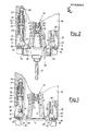
- the figures show diagrammatically the essential elements of the end of a slide 10 designed to carry the connection flange of a tool holder in a clamped condition.
- the slide comprises an axial bore formed with a first short substantially frusto-conical portion 11 connected to a second frusto-conical portion 12'which opens into a cavity 13 carrying the locking control unit 14 of known type for machining centre tools.
- a piston 23 provided with seal gaskets 2 4 is slidably inserted into a suitable chamber in the slide 10.
- a shank 28 slidably inserted into an appropriate seat and provided at its end with a tooth or projection 29.
- a lever 30 is hinged at 31 to the slide 10, and comprises at its two ends respective teeth 32 and 33, of which the first is arranged to cooperate with the projection 29 of the shank 28, and the second is designed to engage with a tool holder, as described hereinafter.
- the lever 30 also comprises a cavity 36 containing a plunger 34 kept urged against the end of the slide 10 by a spring 35.
- the purpose of the plunger 34 is only to keep the lever 30 rotated into the position of Figure 1, i.e. the rest position.
- Figure 1 shows the described device in its rest position, i.e. without any tool applied.
- Figure 2 shows a drilling or any other machining centre tool applied to the slide.
- the drilling tool 37 is rigid with a tool holder 38 comprising a cylindrical plate 39 connected to a frusto-conical shank 40 which terminates in a head 4l (standard tool holder configuration for machining centres).
- Figures 1 and 2 show clearly the rest and locking positions of the device 14, and as this is a conventional device for machining centres neither its operation nor its activating members will be described as these are known to every machining centre expert.
- the plate 44 In contrast to the machining centre tool, the plate 44 abuts against the slide base 48, and the shank 46 is inserted into the bore 12 but without mating with its surface.
- the end 47 is " locked . exactly as in the case shown in Figure 2, by which the tool 42 is clamped axially by means of initial pre-locking.
- the special configuration of the tool holder of which the upper base from which the shank 46 extends perfectly mates with the base 48 of the slide and its initial frusto-conical portion 11, results in advantageous pre-centering and centering of the tool holder.
Landscapes
- Engineering & Computer Science (AREA)
- Mechanical Engineering (AREA)
- Gripping On Spindles (AREA)
- Turning (AREA)
- Crushing And Grinding (AREA)
- Mechanical Operated Clutches (AREA)
- Jigs For Machine Tools (AREA)
Priority Applications (1)
| Application Number | Priority Date | Filing Date | Title |
|---|---|---|---|
| AT83200032T ATE29410T1 (de) | 1982-07-29 | 1983-01-11 | Ein schlitten fuer ein drehbankmaschinenzentrum. |
Applications Claiming Priority (2)
| Application Number | Priority Date | Filing Date | Title |
|---|---|---|---|
| IT6795982 | 1982-07-29 | ||
| IT67959/82A IT1155587B (it) | 1982-07-29 | 1982-07-29 | Dispositivo di riferimento e bloccaggio di portautensili per tornitura o fresatura o altri su slitte mobili con mandrino interno di un tornio centro di lavoro |
Publications (3)
| Publication Number | Publication Date |
|---|---|
| EP0102090A2 true EP0102090A2 (fr) | 1984-03-07 |
| EP0102090A3 EP0102090A3 (en) | 1984-10-03 |
| EP0102090B1 EP0102090B1 (fr) | 1987-09-09 |
Family
ID=11306724
Family Applications (1)
| Application Number | Title | Priority Date | Filing Date |
|---|---|---|---|
| EP83200032A Expired EP0102090B1 (fr) | 1982-07-29 | 1983-01-11 | Un chariot de tour-centre d'usinage |
Country Status (6)
| Country | Link |
|---|---|
| US (1) | US4596502A (fr) |
| EP (1) | EP0102090B1 (fr) |
| JP (1) | JPS5924932A (fr) |
| AT (1) | ATE29410T1 (fr) |
| DE (1) | DE3373429D1 (fr) |
| IT (1) | IT1155587B (fr) |
Cited By (1)
| Publication number | Priority date | Publication date | Assignee | Title |
|---|---|---|---|---|
| KR100929665B1 (ko) | 2009-04-06 | 2009-12-04 | 도원주 | 스핀들유닛 |
Families Citing this family (21)
| Publication number | Priority date | Publication date | Assignee | Title |
|---|---|---|---|---|
| DE8517718U1 (de) * | 1985-06-19 | 1986-10-16 | Komet Stahlhalter- Und Werkzeugfabrik Robert Breuning Gmbh, 7122 Besigheim | Werkzeugmaschinenspindel und hierzu passende Werkzeughalter |
| US4789280A (en) * | 1986-04-11 | 1988-12-06 | The Cross Company | Tooling assembly for automatic tool changing |
| JPS63232120A (ja) * | 1987-03-17 | 1988-09-28 | 東洋製罐株式会社 | 液化ガス添加装置の流下バルブ |
| US4844671A (en) * | 1987-05-11 | 1989-07-04 | Gottlieb Guhring Kg | Coupling device |
| US4919023A (en) * | 1988-03-22 | 1990-04-24 | Bloink Harry W | Quick-change tool adapter |
| DE4404725A1 (de) * | 1994-02-16 | 1995-08-17 | Beck August Gmbh Co | Ausrichtadapter |
| US5591358A (en) * | 1994-03-23 | 1997-01-07 | Progressive Tool & Industries Co. | Apparatus for clamping and laser welding |
| DE10151528B4 (de) * | 2001-10-18 | 2004-02-12 | Ds Technologie Werkzeugmaschinenbau Gmbh | Senkrechtdrehmaschine mit einem Vorsatzkopf an einem Werkzeugschieber |
| US7322775B2 (en) * | 2005-06-08 | 2008-01-29 | Van Horssen Charles A | Quick change holder for cutting tool |
| US7153069B1 (en) * | 2005-06-08 | 2006-12-26 | Van Horssen Charles A | Quick change holder for cutting tool |
| US7575399B2 (en) * | 2005-06-08 | 2009-08-18 | Van Horssen Charles A | Quick change holder for cutting tool |
| DE102008060297B3 (de) * | 2008-12-03 | 2010-07-15 | Boehringer Werkzeugmaschinen Gmbh | Drehmaschine |
| JP5374771B2 (ja) * | 2009-11-10 | 2013-12-25 | 株式会社森精機製作所 | 工作機械および工具ホルダ |
| JP3183660U (ja) * | 2013-03-13 | 2013-05-30 | ファナック株式会社 | マシニングセンタの非回転工具を取り付ける工具ホルダ |
| CN104440097B (zh) * | 2013-09-17 | 2017-01-11 | 富鼎电子科技(嘉善)有限公司 | 车铣复合进给装置,车铣复合机床及其加工方法 |
| JP6301985B2 (ja) * | 2016-02-19 | 2018-03-28 | ファナック株式会社 | 工作機械の主軸位相割出し装置 |
| US10464165B2 (en) * | 2016-08-02 | 2019-11-05 | Nakamura-Tome Precision Industry Co., Ltd. | Combined machining apparatus having a laser machining head |
| US20230147655A1 (en) * | 2020-04-17 | 2023-05-11 | Fanuc Corporation | Machine tool |
| US20230146160A1 (en) * | 2020-04-17 | 2023-05-11 | Fanuc Corporation | Machine tool |
| JP7443470B1 (ja) * | 2022-11-16 | 2024-03-05 | Dmg森精機株式会社 | 工具支持装置、及び該工具支持装置を備えた工作機械 |
| CN121290133B (zh) * | 2025-12-10 | 2026-03-31 | 浙江瑞宏自动化科技有限公司 | 一种主轴拉刀装置 |
Family Cites Families (11)
| Publication number | Priority date | Publication date | Assignee | Title |
|---|---|---|---|---|
| DE725991C (de) * | 1938-03-01 | 1942-10-03 | Ufficio Tecnico Ind Tessili Ar | Vorrichtung an Drehbaenken zum raschen Auswechseln auf Vorrat gehaltener Werkzeugtraeger mit bereits in Beziehung zur Arbeitsachse eingestellten Werkzeugen |
| GB826600A (en) * | 1958-04-28 | 1960-01-13 | Nat Acme Co | Improvements in chuck mechanism |
| DE1300776B (de) * | 1965-06-29 | 1969-08-07 | Forkardt Paul Kg | Vorderend-Spannfutter |
| US3593614A (en) * | 1968-05-24 | 1971-07-20 | Innocenti Societa General Per | Chuck device for releasably attaching a milling cutter to a machine tool spindle |
| FR2229505B1 (fr) * | 1973-05-17 | 1976-10-15 | Toyoda Machine Works Ltd | |
| JPS532514A (en) * | 1976-06-29 | 1978-01-11 | Sumitomo Electric Industries | Manufacture of diamond sintered articles |
| CH595987A5 (fr) * | 1976-07-01 | 1978-02-28 | Graphicart Int | |
| JPS6033616B2 (ja) * | 1976-07-30 | 1985-08-03 | 日立精機株式会社 | 大径工具と小径工具を併用し得る工具主軸 |
| JPS6216261Y2 (fr) * | 1978-07-21 | 1987-04-24 | ||
| US4354305A (en) * | 1978-12-21 | 1982-10-19 | Giddings & Lewis, Inc. | Contouring and threading attachment for multi-function machine tools |
| DE2945770C2 (de) * | 1979-11-13 | 1986-10-30 | K. Eugen Ing.(grad.) 7000 Stuttgart Sigloch | Bearbeitungszentrum |
-
1982
- 1982-07-29 IT IT67959/82A patent/IT1155587B/it active
-
1983
- 1983-01-11 EP EP83200032A patent/EP0102090B1/fr not_active Expired
- 1983-01-11 US US06/457,276 patent/US4596502A/en not_active Expired - Fee Related
- 1983-01-11 DE DE8383200032T patent/DE3373429D1/de not_active Expired
- 1983-01-11 AT AT83200032T patent/ATE29410T1/de not_active IP Right Cessation
- 1983-03-18 JP JP58044518A patent/JPS5924932A/ja active Pending
Cited By (1)
| Publication number | Priority date | Publication date | Assignee | Title |
|---|---|---|---|---|
| KR100929665B1 (ko) | 2009-04-06 | 2009-12-04 | 도원주 | 스핀들유닛 |
Also Published As
| Publication number | Publication date |
|---|---|
| EP0102090A3 (en) | 1984-10-03 |
| EP0102090B1 (fr) | 1987-09-09 |
| IT1155587B (it) | 1987-01-28 |
| DE3373429D1 (en) | 1987-10-15 |
| JPS5924932A (ja) | 1984-02-08 |
| ATE29410T1 (de) | 1987-09-15 |
| IT8267959A0 (it) | 1982-07-29 |
| US4596502A (en) | 1986-06-24 |
Similar Documents
| Publication | Publication Date | Title |
|---|---|---|
| EP0102090A2 (fr) | Un chariot de tour-centre d'usinage | |
| JP2774539B2 (ja) | カップリング装置 | |
| CA1070987A (fr) | Dispositif de bridage | |
| JPS643602B2 (fr) | ||
| US5133565A (en) | Expanding collet | |
| US2816770A (en) | Tool holder and adapter | |
| US4982970A (en) | Claw unit with paired separably connected claw elements | |
| EP0668807B1 (fr) | Tige pour outil de fraisage, comportant des evidements destines a cooperer avec un mandrin | |
| JPH02243209A (ja) | 工作機械主軸用工具アダプタ | |
| US4978262A (en) | Tool coupling between a toolholder and a machine spindle | |
| US4777714A (en) | Quick-change mount for chucks | |
| US4580472A (en) | Cutting tool with interchangeable tool head for machine tools | |
| US5391027A (en) | Machine tool system | |
| US4850765A (en) | Self-locking tool and socket | |
| US5716058A (en) | Chuck | |
| EP0684884B1 (fr) | Dispositif de fixation pour fraiseuses et machines similaires et adaptable a des dimensions de support differentes | |
| US4640517A (en) | Collet chuck | |
| US4686757A (en) | Machine tool chuck construction | |
| EP0091891A2 (fr) | Dispositif de serrage d'outils | |
| US1982719A (en) | Tool | |
| GB2159736A (en) | Clamping device for tools, such as drills, milling cutters or the like | |
| EP0013646A1 (fr) | Assemblage d'un mandrin et d'une pince de serrage | |
| US3133740A (en) | Hydraulic type holder for drill chucks and the like | |
| WO1983003562A1 (fr) | Arbre pour des machines a tailler des engrenages | |
| SU1400847A1 (ru) | Технологический спутник |
Legal Events
| Date | Code | Title | Description |
|---|---|---|---|
| PUAI | Public reference made under article 153(3) epc to a published international application that has entered the european phase |
Free format text: ORIGINAL CODE: 0009012 |
|
| AK | Designated contracting states |
Designated state(s): AT BE CH DE FR GB LI LU NL SE |
|
| PUAL | Search report despatched |
Free format text: ORIGINAL CODE: 0009013 |
|
| AK | Designated contracting states |
Designated state(s): AT BE CH DE FR GB LI LU NL SE |
|
| 17P | Request for examination filed |
Effective date: 19850313 |
|
| 17Q | First examination report despatched |
Effective date: 19860303 |
|
| D17Q | First examination report despatched (deleted) | ||
| GRAA | (expected) grant |
Free format text: ORIGINAL CODE: 0009210 |
|
| AK | Designated contracting states |
Kind code of ref document: B1 Designated state(s): AT BE CH DE FR GB LI LU NL SE |
|
| PG25 | Lapsed in a contracting state [announced via postgrant information from national office to epo] |
Ref country code: NL Effective date: 19870909 Ref country code: LI Effective date: 19870909 Ref country code: CH Effective date: 19870909 Ref country code: BE Effective date: 19870909 Ref country code: AT Effective date: 19870909 |
|
| REF | Corresponds to: |
Ref document number: 29410 Country of ref document: AT Date of ref document: 19870915 Kind code of ref document: T |
|
| PG25 | Lapsed in a contracting state [announced via postgrant information from national office to epo] |
Ref country code: SE Effective date: 19870930 |
|
| REF | Corresponds to: |
Ref document number: 3373429 Country of ref document: DE Date of ref document: 19871015 |
|
| ET | Fr: translation filed | ||
| REG | Reference to a national code |
Ref country code: CH Ref legal event code: PL |
|
| PG25 | Lapsed in a contracting state [announced via postgrant information from national office to epo] |
Ref country code: LU Free format text: LAPSE BECAUSE OF NON-PAYMENT OF DUE FEES Effective date: 19880131 |
|
| NLV1 | Nl: lapsed or annulled due to failure to fulfill the requirements of art. 29p and 29m of the patents act | ||
| PLBE | No opposition filed within time limit |
Free format text: ORIGINAL CODE: 0009261 |
|
| STAA | Information on the status of an ep patent application or granted ep patent |
Free format text: STATUS: NO OPPOSITION FILED WITHIN TIME LIMIT |
|
| 26N | No opposition filed | ||
| GBPC | Gb: european patent ceased through non-payment of renewal fee | ||
| PG25 | Lapsed in a contracting state [announced via postgrant information from national office to epo] |
Ref country code: GB Free format text: LAPSE BECAUSE OF NON-PAYMENT OF DUE FEES Effective date: 19881122 |
|
| PGFP | Annual fee paid to national office [announced via postgrant information from national office to epo] |
Ref country code: FR Payment date: 19911219 Year of fee payment: 10 |
|
| PGFP | Annual fee paid to national office [announced via postgrant information from national office to epo] |
Ref country code: DE Payment date: 19920129 Year of fee payment: 10 |
|
| PG25 | Lapsed in a contracting state [announced via postgrant information from national office to epo] |
Ref country code: FR Effective date: 19930930 |
|
| PG25 | Lapsed in a contracting state [announced via postgrant information from national office to epo] |
Ref country code: DE Effective date: 19931001 |
|
| REG | Reference to a national code |
Ref country code: FR Ref legal event code: ST |