EP0102139A2 - Sources cathodolumineuses et installations électriques comportant de telles sources - Google Patents
Sources cathodolumineuses et installations électriques comportant de telles sources Download PDFInfo
- Publication number
- EP0102139A2 EP0102139A2 EP83302442A EP83302442A EP0102139A2 EP 0102139 A2 EP0102139 A2 EP 0102139A2 EP 83302442 A EP83302442 A EP 83302442A EP 83302442 A EP83302442 A EP 83302442A EP 0102139 A2 EP0102139 A2 EP 0102139A2
- Authority
- EP
- European Patent Office
- Prior art keywords
- anode
- neck
- lamp
- bulb
- coating
- Prior art date
- Legal status (The legal status is an assumption and is not a legal conclusion. Google has not performed a legal analysis and makes no representation as to the accuracy of the status listed.)
- Ceased
Links
- 229910052751 metal Inorganic materials 0.000 claims abstract description 38
- 239000002184 metal Substances 0.000 claims abstract description 38
- 238000000576 coating method Methods 0.000 claims abstract description 31
- 239000011248 coating agent Substances 0.000 claims abstract description 30
- 239000011521 glass Substances 0.000 claims abstract description 27
- OAICVXFJPJFONN-UHFFFAOYSA-N Phosphorus Chemical compound [P] OAICVXFJPJFONN-UHFFFAOYSA-N 0.000 claims abstract description 9
- 239000012799 electrically-conductive coating Substances 0.000 claims abstract description 4
- WABPQHHGFIMREM-UHFFFAOYSA-N lead(0) Chemical compound [Pb] WABPQHHGFIMREM-UHFFFAOYSA-N 0.000 claims description 7
- 229910003437 indium oxide Inorganic materials 0.000 claims description 3
- PJXISJQVUVHSOJ-UHFFFAOYSA-N indium(iii) oxide Chemical compound [O-2].[O-2].[O-2].[In+3].[In+3] PJXISJQVUVHSOJ-UHFFFAOYSA-N 0.000 claims description 3
- XOLBLPGZBRYERU-UHFFFAOYSA-N tin dioxide Chemical compound O=[Sn]=O XOLBLPGZBRYERU-UHFFFAOYSA-N 0.000 claims description 3
- 229910001887 tin oxide Inorganic materials 0.000 claims description 3
- 238000004020 luminiscence type Methods 0.000 claims description 2
- PXHVJJICTQNCMI-UHFFFAOYSA-N Nickel Chemical compound [Ni] PXHVJJICTQNCMI-UHFFFAOYSA-N 0.000 description 8
- 239000000463 material Substances 0.000 description 4
- 229910052759 nickel Inorganic materials 0.000 description 4
- OKTJSMMVPCPJKN-UHFFFAOYSA-N Carbon Chemical compound [C] OKTJSMMVPCPJKN-UHFFFAOYSA-N 0.000 description 3
- 229910052799 carbon Inorganic materials 0.000 description 3
- BQCADISMDOOEFD-UHFFFAOYSA-N Silver Chemical compound [Ag] BQCADISMDOOEFD-UHFFFAOYSA-N 0.000 description 2
- 238000010438 heat treatment Methods 0.000 description 2
- 238000009413 insulation Methods 0.000 description 2
- 238000004519 manufacturing process Methods 0.000 description 2
- 239000003973 paint Substances 0.000 description 2
- 229910052709 silver Inorganic materials 0.000 description 2
- 239000004332 silver Substances 0.000 description 2
- 239000010935 stainless steel Substances 0.000 description 2
- 229910001220 stainless steel Inorganic materials 0.000 description 2
- 229910001369 Brass Inorganic materials 0.000 description 1
- 229910000640 Fe alloy Inorganic materials 0.000 description 1
- 229910001030 Iron–nickel alloy Inorganic materials 0.000 description 1
- RTAQQCXQSZGOHL-UHFFFAOYSA-N Titanium Chemical compound [Ti] RTAQQCXQSZGOHL-UHFFFAOYSA-N 0.000 description 1
- 239000004411 aluminium Substances 0.000 description 1
- 229910052782 aluminium Inorganic materials 0.000 description 1
- XAGFODPZIPBFFR-UHFFFAOYSA-N aluminium Chemical compound [Al] XAGFODPZIPBFFR-UHFFFAOYSA-N 0.000 description 1
- 229910052788 barium Inorganic materials 0.000 description 1
- DSAJWYNOEDNPEQ-UHFFFAOYSA-N barium atom Chemical compound [Ba] DSAJWYNOEDNPEQ-UHFFFAOYSA-N 0.000 description 1
- 230000005540 biological transmission Effects 0.000 description 1
- 239000010951 brass Substances 0.000 description 1
- 239000004020 conductor Substances 0.000 description 1
- 239000011888 foil Substances 0.000 description 1
- 239000011810 insulating material Substances 0.000 description 1
- 238000002955 isolation Methods 0.000 description 1
- 239000010936 titanium Substances 0.000 description 1
- 229910052719 titanium Inorganic materials 0.000 description 1
- WFKWXMTUELFFGS-UHFFFAOYSA-N tungsten Chemical class [W] WFKWXMTUELFFGS-UHFFFAOYSA-N 0.000 description 1
Images

Classifications
-
- H—ELECTRICITY
- H01—ELECTRIC ELEMENTS
- H01J—ELECTRIC DISCHARGE TUBES OR DISCHARGE LAMPS
- H01J63/00—Cathode-ray or electron-stream lamps
- H01J63/06—Lamps with luminescent screen excited by the ray or stream
Definitions
- This invention relates to cathodoluminescent light sources in the form of electric lamps which are suitable for use for general lighting purposes, and to electric lighting arrangements including such lamps.
- a cathodoluminescent lamp which includes an evacuated bulbous glass envelope with an integral glass neck terminated by a cap, an anode constituted by an electrically conductive coating on the interior surface of the bulb wall, such that at least part of the bulb wall is light-transmissive, a phosphor coating on the whole of the interior of the bulb wall and overlying the anode coating, a dome-shaped grid located within the bulb and supported by a hollow metal cylinder disposed within the envelope neck, and an electron emissive cathode mounted within the assembly of the grid and its supporting cylinder.
- the current-conducting leads to the cathode and the grid are sealed into the closure of the envelope neck, suitably a pinched glass foot tube, and extend to contacts on the lamp cap, and the lead to the anode is located along the exterior of the neck, being sealed through the envelope wall for connection to the anode coating, and extending to a contact provided on the exterior of the neck.
- the anode lead is mainly laid close to the interior surface of the envelope neck, so as to be spaced as far as possible from the cathode and grid leads, and the portion of the anode lead extending from the vicinity of the neck wall to the exahust tube is covered by a glass sleeve, for insulation; for connection of the anode coating to the anode lead, a coating of carbon is applied to the interior surface of the neck-bulb junction region of the envelope, covering the edge region of the anode coating, and the lead is attached to the carbon coating by means of a silver paint contact applied over the inner end of the lead in contact with the carbon.
- a cathodoluminescent lamp which includes an evacuated bulbous glass envelope with an integral glass neck closed by a pinched glass foot tube incorporating an exhaust tube located around the longitudinal axis of the foot tube, the foot tube terminating in a cap, an anode constituted by an electrically conductive coating on at least part of the interior surface of the bulb wall, such that at least part of the bulb wall is light-transmissive, a layer of phosphor on the whole of the interior of the bulb wall and overlying the said anode coating, which phosphor is excitable to luminescence by electron bombardment, a dome-shaped grid located within the bulb adjacent to the junction between the bulb and neck of the envelope and supported by a hollow metal cylinder disposed coaxially within the neck, an electron emissive cathode mounted within the assembly of the grid and its supporting cylinder, electrically conducting leads, all located wholly within the envelope neck and foot tube, connecting the anode, grid and cathode to respective external contacts carried by the said cap
- the end of the anode lead wire may be bent to form a hook to engage with the contact strip, or alternatively a short length of metal strip may be attached to the end of the wire and bent to the required shape; if desired such metal strip may be of sufficient length, and so shaped, to make additional contact with the anode coating on the neck.
- the internal anode connection arrangement in accordance with the invention is advantageous in that it facilitates the assembly of the lamp in manufacture. Furthermore, the arrangement of the leads in the pinched foot tube, described above, with the anode lead surrounded by the additional glass tube, provides improved isolation of the anode lead from the grid and cathode leads, which is desirable in view of the fact that a high potential is required to be applied to the anode for operation of the lamp.
- the portion of the anode lead extending from the pinch to the metal strip contact on the neck should be located at as great a distance as possible from the grid and cathode leads and the grid-supporting cylinder, and may if desired be insulated, at least partially, by a surrounding glass sleeve.
- the anode coating preferably covers the whole of the interior surface of the bulb wall, as well as part of the neck wall as aforesaid, and may consist of a known type of light-transmissive electrically conducting coating formed, for example, of tin oxide and/or indium oxide.
- part of the bulb may be provided with an internal reflective metal coating which also serves as at least part of the anode, the remainder of the bulb either being free from any conductive coating or, preferably, having a light-transmissive conductive coating to provide continuity of the anode over the whole of the bulb wall.
- the cathode should be, as specified in the specification of Application No.8102935, so shaped, and/ or so located within the grid assembly, that the electrons emitted from the cathode in operation of the lamp are substantially uniformly distributed over the whole of the surface of the grid on which they impinge.
- the cathode may be of effectively circular form, consisting either of a directly heated coil filament of "wreath" form incorporating electron emissive material, or of an indirectly heated hollow metal cylinder capped with a metal disc coated externally with electron emissive material, in either case the electron emissive part of the cathode being located in the region of the junction between the grid and the metal cylinder.
- the cathode may consist of a directly heated linear coil filament located within the grid-supporting cylinder and disposed either orthogonally to, or coaxially with, the cylinder axis.
- Another suitable form of cathode consists of a directly heated body formed of metal mesh or perforated metal foil, preferably a strip bent into a U shape and mounted with the base of the U, which carries electron emissive material, facing towards the grid and located within the grid-supporting cylinder a short distance from the plane of the base of the grid.
- the invention further provides an electric lighting arrangement consisting of a lamp of the form described above, and a circuit arrangement for operating the said lamp from a source of electric current supply, which circuit arrangement includes means for converting the supply voltage to unidirectional operating potentials of required magnitudes for application respectively to the anode, cathode and grid of the lamp. Suitable operating potentials are 5 to 15 kilovolts applied to the anode, 40 to 250 volts applied to the grid, and a cathode potential lower than that applied to the grid.
- the circuit arrangement may be contained within a housing which is detachably mounted on the lamp cap and is insertable into a lampholder, or may be incorporated in a lampholder, the housing or lampholder being provided with contacts arranged to co-operate with the contacts on the lamp cap.
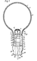
- the lamp shown in Figure 1 which is designed for general lighting service, comprises an evacuated envelope formed of any suitable glass which will inhibit the transmission of X-rays generated by the electron bombardment of the envelope in operation of the lamp, and consisting of a spherical bulb 1 and an integral - neck 2 in which an electron gun assembly is mounted, . supported from a pinched glass foot tube 3 which is sealed into the neck opening in conventional manner; a brass cap 4 is cemented on to the neck, also in conventional manner.
- a metal strip 5 is attached to the interior surface of the envelope neck, a short distance below the junction of the neck with the bulb 1.
- This strip is suitably formed of a nickel-iron alloy containing 48% of weight of nickel, and is shaped as shown in Figure 2 of the drawings, which is a perspective view of the metal strip and a portion of the neck as observed through the bulb: thus the strip is bent to form a central upstanding portion 6, spaced from the neck surface, the flat end portions 7 being secured to the glass.
- the metal strip is 1 mm wide and 0.1 mm thick, the end portions 7 are 2 mm long, and the sides of the upstanding portion 6 are each 1.5 mm long.
- the electron gun assembly consists of a dome-shaped grid 10 formed of metal wire mesh, supported on a hollow metal cylinder 11, to which a support/lead wire 12 is attached, a cathode 13 in the form of a tungsten wire helix incorporating electron emissive material, disposed coaxially with the cylinder 11 and with its upper end about 2 mm below the plane of the base of the grid, and supported on lead wires 14, and a metal disc 15 with a central aperture 16 to permit passage of the cathode leads therethrough, the disc being located within the cylinder 11 close to the open end thereof, insulated from the cylinder by a glass sleeve 17 fitted inside the cylinder, and supported by a wire 18 which is attached to one of the cathode leads 14 which is the negative lead to the cathode in operation.
- the function of the disc 15 is to act as a baffle plate for obstructing any electrons emitted by the cathode in operation which, in the absence of the disc, would escape through the open lower end of the cylinder 11 and would be attracted to the interior surface of the envelope neck, which is positively charged in operation, thus heating the neck and possibly causing it to crack.
- the wire mesh grid may suitably be formed of nickel or stainless steel.
- the cylinder 11 and disc 15 are preferably formed of titanium, but may be of other metal such as nickel or stainless steel.
- the grid lead wire 12, the cathode lead wires 14, and the baffle disc support wire 18 are suitably all of nickel.
- the foot tube 3 incorporates a glass exhaust tube 19, extending from the pinch 20 in conventional manner, and an additional glass tube 21 also extending from the pinch, substantially parallel to the exhaust tube.
- the metal strip 5 forms a contact to the anode, and the wire 22 thus constitutes the lead to the anode, and is connected to a pin contact 24 carried by the insulating closure of the lamp cap 4.
- the grid lead 12 and cathode leads 14 are sealed through the part of the pinch which is on the opposite side of the exhaust tube to that part of the pinch in which the tube 21 and anode lead 22 are located.
- the grid lead 12 is connected at 25 to the cap 4 which thus constitutes the grid contact on the lamp.
- the cathode leads 14 are connected to contacts 26 carried by the cap insulation, the location of the cathode leads within the cap being spaced as far as possible from that portion of the anode lead extending from the lower end of the tube 21 to the contact 24, so that the anode and cathode leads are insulated from one another by the insulating material (not shown) inside the cap.
- Barium/aluminium getter rings 27, of known form, are supported within the envelope neck by wires 28 attached to the grid lead wire 12.
- the cap 4 is provided with locating pins 29, preferably three in number, to ensure correct orientation of the lamp in a lampholder or housing for the required connection of the respective contacts 24, 25 and 26 to an operating circuit.
- the metal strip anode contact 5 is first placed in position on the neck surface and is secured to the glass by heating the exterior of the requisite portion of the neck with a flame, sufficiently to soften the glass and cause it to bond to the metal.
- the conducting film 8 is then applied to the interior surface of the bulb and part of the neck as aforesaid, in known manner, the joints between the conducting film and the contact strip 5 are covered with silver paint, and the phosphor coating 9 is applied over the film 8 on the bulb.
Landscapes
- Vessels And Coating Films For Discharge Lamps (AREA)
- Discharge Lamps And Accessories Thereof (AREA)
Applications Claiming Priority (2)
| Application Number | Priority Date | Filing Date | Title |
|---|---|---|---|
| GB8223872 | 1982-08-19 | ||
| GB8223872 | 1982-08-19 |
Publications (2)
| Publication Number | Publication Date |
|---|---|
| EP0102139A2 true EP0102139A2 (fr) | 1984-03-07 |
| EP0102139A3 EP0102139A3 (fr) | 1984-11-07 |
Family
ID=10532398
Family Applications (1)
| Application Number | Title | Priority Date | Filing Date |
|---|---|---|---|
| EP83302442A Ceased EP0102139A3 (fr) | 1982-08-19 | 1983-04-29 | Sources cathodolumineuses et installations électriques comportant de telles sources |
Country Status (3)
| Country | Link |
|---|---|
| US (1) | US4506194A (fr) |
| EP (1) | EP0102139A3 (fr) |
| GB (1) | GB2126006B (fr) |
Cited By (5)
| Publication number | Priority date | Publication date | Assignee | Title |
|---|---|---|---|---|
| WO1997007531A1 (fr) * | 1995-08-14 | 1997-02-27 | E.I. Du Pont De Nemours And Company | Lampe fluorescente |
| US6020677A (en) * | 1996-11-13 | 2000-02-01 | E. I. Du Pont De Nemours And Company | Carbon cone and carbon whisker field emitters |
| CN102549703A (zh) * | 2009-03-30 | 2012-07-04 | Vu1公司 | 制造阴极射线发光装置的系统和方法 |
| EP2503588A3 (fr) * | 2008-09-12 | 2013-08-28 | VU1 Corporation | Système pour éclairage cathodoluminescent |
| PL424797A1 (pl) * | 2018-03-08 | 2019-09-09 | Instytut Tele- I Radiotechniczny | Lampa z zimną katodą do generacji światła UV |
Families Citing this family (9)
| Publication number | Priority date | Publication date | Assignee | Title |
|---|---|---|---|---|
| SE510412C2 (sv) * | 1997-06-13 | 1999-05-25 | Lightlab Ab | En ljuskälla innefattande en fältemissionskatod och en fältemissionskatod för användning i en ljuskälla |
| SE510413C2 (sv) * | 1997-06-13 | 1999-05-25 | Lightlab Ab | En fältemissionskatod och en ljuskälla innefattande en fältemissionskatod |
| DE19844548A1 (de) * | 1998-09-29 | 2000-03-30 | Patent Treuhand Ges Fuer Elektrische Gluehlampen Mbh | Entladungslampe und Beleuchtungssystem mit einer Entladungslampe |
| GB2346007B (en) | 1999-01-21 | 2004-03-03 | Imaging & Sensing Tech Corp | Getter flash shield |
| CN100530512C (zh) * | 2004-07-20 | 2009-08-19 | 清华大学 | 一种场发射灯管 |
| TW200723348A (en) * | 2005-12-09 | 2007-06-16 | Ind Tech Res Inst | Light source for projection system |
| CN100573808C (zh) * | 2006-03-22 | 2009-12-23 | 清华大学 | 场发射照明光源及其制造方法 |
| US20080192458A1 (en) * | 2007-02-12 | 2008-08-14 | Intematix Corporation | Light emitting diode lighting system |
| US8807799B2 (en) * | 2010-06-11 | 2014-08-19 | Intematix Corporation | LED-based lamps |
Family Cites Families (8)
| Publication number | Priority date | Publication date | Assignee | Title |
|---|---|---|---|---|
| NL83170C (fr) * | 1952-01-15 | |||
| BE545577A (fr) * | 1955-02-26 | |||
| US4173730A (en) * | 1978-07-11 | 1979-11-06 | Westinghouse Electric Corp. | Compact fluorescent lamp unit having integral circuit means for DC operation |
| GB2072958B (en) * | 1979-09-06 | 1983-09-01 | English Electric Valve Co Ltd | Lamps |
| US4270071A (en) * | 1979-11-26 | 1981-05-26 | Westinghouse Electric Corp. | Composite base and ballast member for compact single-ended fluorescent lamp |
| GB2070849B (en) * | 1980-02-27 | 1983-11-09 | Gen Electric Co Ltd | Cathodoluminescent lamps |
| US4344015A (en) * | 1980-08-18 | 1982-08-10 | Rca Corporation | Screen contact means for a cathode ray tube |
| EP0054356A1 (fr) * | 1980-12-17 | 1982-06-23 | THE GENERAL ELECTRIC COMPANY, p.l.c. | Source lumineuse à cathodoluminescence et installations d'éclairage comprenant de telles sources lumineuses |
-
1983
- 1983-04-29 EP EP83302442A patent/EP0102139A3/fr not_active Ceased
- 1983-04-29 GB GB08311891A patent/GB2126006B/en not_active Expired
- 1983-05-16 US US06/494,905 patent/US4506194A/en not_active Expired - Fee Related
Cited By (8)
| Publication number | Priority date | Publication date | Assignee | Title |
|---|---|---|---|---|
| WO1997007531A1 (fr) * | 1995-08-14 | 1997-02-27 | E.I. Du Pont De Nemours And Company | Lampe fluorescente |
| AU696412B2 (en) * | 1995-08-14 | 1998-09-10 | E.I. Du Pont De Nemours And Company | Fluorescent lamp |
| US6020677A (en) * | 1996-11-13 | 2000-02-01 | E. I. Du Pont De Nemours And Company | Carbon cone and carbon whisker field emitters |
| EP2503588A3 (fr) * | 2008-09-12 | 2013-08-28 | VU1 Corporation | Système pour éclairage cathodoluminescent |
| CN102549703A (zh) * | 2009-03-30 | 2012-07-04 | Vu1公司 | 制造阴极射线发光装置的系统和方法 |
| EP2415064A4 (fr) * | 2009-03-30 | 2012-12-12 | Vu1 Corp | Système et procédé de fabrication d'un dispositif d'éclairage cathodoluminescent |
| PL424797A1 (pl) * | 2018-03-08 | 2019-09-09 | Instytut Tele- I Radiotechniczny | Lampa z zimną katodą do generacji światła UV |
| PL234120B1 (pl) * | 2018-03-08 | 2020-01-31 | Inst Tele I Radiotech | Lampa z zimną katodą do generacji światła UV |
Also Published As
| Publication number | Publication date |
|---|---|
| US4506194A (en) | 1985-03-19 |
| GB2126006B (en) | 1985-11-27 |
| GB8311891D0 (en) | 1983-06-02 |
| EP0102139A3 (fr) | 1984-11-07 |
| GB2126006A (en) | 1984-03-14 |
Similar Documents
| Publication | Publication Date | Title |
|---|---|---|
| US4352043A (en) | Cathodoluminescent light sources and electric lighting arrangements including such sources | |
| US4506194A (en) | Cathodoluminescent light sources and electric lighting arrangements including such sources | |
| US8058789B2 (en) | Cathodoluminescent phosphor lamp having extraction and diffusing grids and base for attachment to standard lighting fixtures | |
| US4281267A (en) | High intensity discharge lamp with coating on arc discharge tube | |
| US4843266A (en) | Metal-halogen discharge lamp with conically shaped insulating elements in outer envelope | |
| US7728505B2 (en) | Field emission luminescent light source within a bulb | |
| US5210461A (en) | Arc discharge lamp containing mechanism for extinguishing arc at end-of-life | |
| US2201720A (en) | Thermionic cathode structure | |
| US3826946A (en) | Vapor discharge lamp electrode having carbon-coated areas | |
| GB2097181A (en) | Cathodoluminescent lamps | |
| EP0054356A1 (fr) | Source lumineuse à cathodoluminescence et installations d'éclairage comprenant de telles sources lumineuses | |
| CN1177825A (zh) | 阴极构件及使用该阴极构件的crt电子枪 | |
| JP2002042735A (ja) | 蛍光ランプ | |
| US2838705A (en) | Color-corrected reflector high pressure mercury vapor lamp and method of preparing | |
| US2757300A (en) | Reflector type incandescent or gas discharge-electroluminescent lamp | |
| US2009211A (en) | Gaseous electric discharge device | |
| US5276379A (en) | Arc discharge lamp having cementless base members | |
| US1945979A (en) | Electron discharge tube | |
| US5025190A (en) | Glow discharge lamp | |
| US2312246A (en) | Electric discharge device | |
| US1945746A (en) | Electron discharge device with indirectly heated cathode | |
| JPH0447949B2 (fr) | ||
| US5006762A (en) | Negative glow fluorescent lamp having discharge barrier | |
| US2030521A (en) | Electric discharge tube | |
| JPH0762992B2 (ja) | 反射形メタルハライドランプ |
Legal Events
| Date | Code | Title | Description |
|---|---|---|---|
| PUAI | Public reference made under article 153(3) epc to a published international application that has entered the european phase |
Free format text: ORIGINAL CODE: 0009012 |
|
| AK | Designated contracting states |
Designated state(s): BE DE FR IT NL |
|
| 17P | Request for examination filed |
Effective date: 19840227 |
|
| PUAL | Search report despatched |
Free format text: ORIGINAL CODE: 0009013 |
|
| AK | Designated contracting states |
Designated state(s): BE DE FR IT NL |
|
| 17Q | First examination report despatched |
Effective date: 19861125 |
|
| RAP1 | Party data changed (applicant data changed or rights of an application transferred) |
Owner name: OSRAM- GEC LIMITED |
|
| STAA | Information on the status of an ep patent application or granted ep patent |
Free format text: STATUS: THE APPLICATION HAS BEEN REFUSED |
|
| 18R | Application refused |
Effective date: 19870828 |
|
| RIN1 | Information on inventor provided before grant (corrected) |
Inventor name: RIGDEN, SYDNEY ALFRED RICHARD Inventor name: SWEET, IAN JAMES HERBERT |