EP0102176B1 - Verfahren und Vorrichtung zur Ultraschallfehlerprüfung - Google Patents
Verfahren und Vorrichtung zur Ultraschallfehlerprüfung Download PDFInfo
- Publication number
- EP0102176B1 EP0102176B1 EP83304211A EP83304211A EP0102176B1 EP 0102176 B1 EP0102176 B1 EP 0102176B1 EP 83304211 A EP83304211 A EP 83304211A EP 83304211 A EP83304211 A EP 83304211A EP 0102176 B1 EP0102176 B1 EP 0102176B1
- Authority
- EP
- European Patent Office
- Prior art keywords
- probes
- axis
- rotation
- detected
- rotary body
- Prior art date
- Legal status (The legal status is an assumption and is not a legal conclusion. Google has not performed a legal analysis and makes no representation as to the accuracy of the status listed.)
- Expired
Links
Images







Classifications
-
- G—PHYSICS
- G01—MEASURING; TESTING
- G01N—INVESTIGATING OR ANALYSING MATERIALS BY DETERMINING THEIR CHEMICAL OR PHYSICAL PROPERTIES
- G01N29/00—Investigating or analysing materials by the use of ultrasonic, sonic or infrasonic waves; Visualisation of the interior of objects by transmitting ultrasonic or sonic waves through the object
- G01N29/44—Processing the detected response signal, e.g. electronic circuits specially adapted therefor
- G01N29/4445—Classification of defects
-
- G—PHYSICS
- G01—MEASURING; TESTING
- G01N—INVESTIGATING OR ANALYSING MATERIALS BY DETERMINING THEIR CHEMICAL OR PHYSICAL PROPERTIES
- G01N29/00—Investigating or analysing materials by the use of ultrasonic, sonic or infrasonic waves; Visualisation of the interior of objects by transmitting ultrasonic or sonic waves through the object
- G01N29/04—Analysing solids
- G01N29/06—Visualisation of the interior, e.g. acoustic microscopy
- G01N29/0609—Display arrangements, e.g. colour displays
- G01N29/0618—Display arrangements, e.g. colour displays synchronised with scanning, e.g. in real-time
-
- G—PHYSICS
- G01—MEASURING; TESTING
- G01N—INVESTIGATING OR ANALYSING MATERIALS BY DETERMINING THEIR CHEMICAL OR PHYSICAL PROPERTIES
- G01N29/00—Investigating or analysing materials by the use of ultrasonic, sonic or infrasonic waves; Visualisation of the interior of objects by transmitting ultrasonic or sonic waves through the object
- G01N29/04—Analysing solids
- G01N29/06—Visualisation of the interior, e.g. acoustic microscopy
- G01N29/0609—Display arrangements, e.g. colour displays
- G01N29/0645—Display representation or displayed parameters, e.g. A-, B- or C-Scan
-
- G—PHYSICS
- G01—MEASURING; TESTING
- G01N—INVESTIGATING OR ANALYSING MATERIALS BY DETERMINING THEIR CHEMICAL OR PHYSICAL PROPERTIES
- G01N29/00—Investigating or analysing materials by the use of ultrasonic, sonic or infrasonic waves; Visualisation of the interior of objects by transmitting ultrasonic or sonic waves through the object
- G01N29/04—Analysing solids
- G01N29/11—Analysing solids by measuring attenuation of acoustic waves
-
- G—PHYSICS
- G01—MEASURING; TESTING
- G01N—INVESTIGATING OR ANALYSING MATERIALS BY DETERMINING THEIR CHEMICAL OR PHYSICAL PROPERTIES
- G01N29/00—Investigating or analysing materials by the use of ultrasonic, sonic or infrasonic waves; Visualisation of the interior of objects by transmitting ultrasonic or sonic waves through the object
- G01N29/22—Details, e.g. general constructional or apparatus details
- G01N29/225—Supports, positioning or alignment in moving situation
-
- G—PHYSICS
- G01—MEASURING; TESTING
- G01N—INVESTIGATING OR ANALYSING MATERIALS BY DETERMINING THEIR CHEMICAL OR PHYSICAL PROPERTIES
- G01N29/00—Investigating or analysing materials by the use of ultrasonic, sonic or infrasonic waves; Visualisation of the interior of objects by transmitting ultrasonic or sonic waves through the object
- G01N29/22—Details, e.g. general constructional or apparatus details
- G01N29/26—Arrangements for orientation or scanning by relative movement of the head and the sensor
- G01N29/265—Arrangements for orientation or scanning by relative movement of the head and the sensor by moving the sensor relative to a stationary material
-
- G—PHYSICS
- G01—MEASURING; TESTING
- G01N—INVESTIGATING OR ANALYSING MATERIALS BY DETERMINING THEIR CHEMICAL OR PHYSICAL PROPERTIES
- G01N29/00—Investigating or analysing materials by the use of ultrasonic, sonic or infrasonic waves; Visualisation of the interior of objects by transmitting ultrasonic or sonic waves through the object
- G01N29/36—Detecting the response signal, e.g. electronic circuits specially adapted therefor
- G01N29/38—Detecting the response signal, e.g. electronic circuits specially adapted therefor by time filtering, e.g. using time gates
-
- G—PHYSICS
- G01—MEASURING; TESTING
- G01N—INVESTIGATING OR ANALYSING MATERIALS BY DETERMINING THEIR CHEMICAL OR PHYSICAL PROPERTIES
- G01N2291/00—Indexing codes associated with group G01N29/00
- G01N2291/04—Wave modes and trajectories
- G01N2291/044—Internal reflections (echoes), e.g. on walls or defects
-
- G—PHYSICS
- G01—MEASURING; TESTING
- G01N—INVESTIGATING OR ANALYSING MATERIALS BY DETERMINING THEIR CHEMICAL OR PHYSICAL PROPERTIES
- G01N2291/00—Indexing codes associated with group G01N29/00
- G01N2291/26—Scanned objects
- G01N2291/269—Various geometry objects
- G01N2291/2693—Rotor or turbine parts
Definitions
- This invention relates to a method and apparatus of ultrasonic flaw detection, and more particularly to a method and apparatus capable of detecting the directions, inclinations, sizes and depths of cavity voids or other internal flaws of various materials for judging the severity of the detected defects.
- Cast stocks sometimes contain oblique cavity voids due to a spout of gases which take place in the casting stage.
- few attempts have been made to analyse the shape of an internal defect in terms of its effect on the strength of a material intended for a specific use, except by simple definitions of the dimensions of a defect as projected on the surface.
- the severity of a cavity void of a given size normally varies depending upon the direction in which it extends e.g. in the X-direction or Y-direction.
- the allowable defect size in the X-direction of a material differs from that in the Y-direction. Under these circumstances, it is a matter of importance to detect the shapes (direction, inclination and size) of internal cavity defects with accuracy.
- ultrasonic methods For the detection of internal defects as mentioned above, ultrasonic methods have been used in which an ultrasonic pulse is transmitted into a material and echoes from the internal defects are detected.
- the conventional ultrasonic methods only transmit and receive the ultrasonic pulses from a single probe scanning along the surface in predetermined directions in an inspection zone of the material. They provide very limited information of the defects from visually recognisable defect echo patterns which are displayed on a display medium and therefore are unable to determine very well the shapes of crosswise cavity defects.
- the present inventors developed a method which employs a rotating inclined probe to transmit and receive the ultrasonic pulse along a path intersecting the rotational axis in an inspection zone of a material under inspection, turning the probe through 360° about the rotational axis while transmitting and receiving ultrasonic pulses, and indicating the peak values of echoes received at a flaw detection gate as a detected flaw pattern on a display medium for judging therefrom the direction, inclination, size and depth of the detected defect.
- This method has a great advantage over the above-mentioned conventional methods in that it is capable of accurately determining the shapes of internal defects such as their direction, inclination and size.
- the inventors' prior method has a drawback that it takes a long time to detect the depth of a defect by a single proble, since the same operation has to be repeated for a number of times, varying the depth of inspection each time. Further, the above-mentioned methods all rely on the operator with regard to the judgement of the severity of a detected defect, which is relatively easy in the flaw detection of a small piece of material but difficult to adopt in the on-line flaw detection of large materials.
- an ultrasonic flaw detection method for detecting internal cavity defects in a material comprising:
- an apparatus for ultrasonic flaw detection for recognising internal cavity defects in a material comprising:
- Figures 1(A) and 1(B) show the path of an ultrasonic pulse 4 in an angled beam ultrasonic flaw detector using a probe 1, the beam having a refraction angle of 8, when detecting a cavity void 3 in a material 2 which void 3 extends with an angle of inclination ri( ⁇ ) to the plane of the surface of the material 2.
- the probe 1 is rotated so as to make one revolution in the arrowed direction about the axis of rotation (O.O') from the start line position 0 .
- the direction of the incident ultrasonic pulse becomes perpendicular to the defect 3 at two different positions, namely, at the angular positions P, P' spaced from the start line OS by rotational angles a, and a 2 .
- the ultrasonic pulse follows the paths P ⁇ Q ⁇ R ⁇ Q ⁇ P and P' ⁇ Q' ⁇ R' ⁇ Q' ⁇ R' respectively in Figure 1. From simple geometric calculations it is known that the angles a, n and 8 have the following relationship as expressed by the Equation (1).
- Figure 2 shows a detected flaw pattern obtained by plotting the direction of incidence a against the peak values of the ultrasonic echoes 4 which were actually transmitted and received sequentially whilst the probe 1 was rotated in the manner shown in Figure 1(B).
- the angular characteristics (i.e. the position of the maxima) of the detected flaw pattern are defined by the Equation (1), and the maximum peak value depends on the size of the defect 3.
- the flaw detection pattern of Figure 2 contains data with regard to the direction, inclination and size of the defect 3.
- the direction of the start line is selected such that it coincides with a particular direction related to the shape of the material 2 to be inspected, for example, the longitudinal direction OL of the material 2, so that, in practice the defect 3 is measured from the start line OL.
- the direction of the defect 3 is expressed by the following formulae.
- the inclination r l of the defect 3 is expressed by the following equations.
- the correlation processing is expressed by the following equation. in which f(a) and r(a) are arbitrary functions defined by 0 ⁇ a ⁇ 360.
- the correlation processing which has recently been applied to pattern recognition in image processing technology and to error corrections in communication technology is used in the present embodiment of the invention to compare the detected flaw pattern of an unknown defect with a number of reference patterns, to determine the reference flaw pattern which is most similar to the detected flaw pattern.
- the reference patterns are prepared from actually measured values derived from artificial cylindrical drilled holes or by calculation according to Equation (1). Since the characteristics (directions, inclinations, etc.) of the artificial cylindrical drilled holes are known, the amount of deviation S gives the discrepancy between the direction of a cylindrical drilled hole and a detected defect.
- a number of reference patterns are prepared, for example, from 10 kinds of cylindrical drilled holes which are the same with respect to the direction, length and depth of the reflecting surface but which have different angles of inclination n of 0, 5, 10, 15,20, 25, 30, 35, 40 and 45 degrees, respectively.
- a detected flaw detection pattern may then be correlated with the respective reference patterns for the detection of the direction and inclination of the defect. In this way, the defect can be easily classified if the values of the maxima of the reference patterns are set at a predetermined level.
- the correlation method which is often used for the improvement of signal to noise ratio in signal processing can also be effectively applied to those cases where the detected flaw pattern contains noise as shown in Figure 4.
- the detected flaw patterns usually contain such noise so that it becomes extremely difficult for the machines to measure the number of peaks and the peak-to-peak distances correctly.
- FIG. 5 there is illustrated an apparatus for carrying out a flaw detection method of the present invention, employing four probes.
- a support plate 5 which is movable in the directions of X- and Y-axes for scanning purposes, and supports on its underside a water tank 6 which is movable across the material 2 to be inspected.
- the water tank 6 accommodates a probe rotating mechanism 7 and contains water 8.
- the probe rotating mechanism 7 includes a cylindrical shaft 12 which is rotatably supported in a bearing box 11 on the support plate 5 by bearings 9 and 10, and a probe holder 13 which is mounted at the lower end of this shaft 12 and has four inclined probes 14 to 17 built thereinto at intervals of 90° in the circumferential direction.
- the probes 14 to 17 are adapted to inspect at a range of 20 mm from the surface of the material 2 at a scanning pitch of 8 mm in this particular example although the invention is not limited to any specific range or pitch.
- the respective probes 14 to 17 are arranged to transmit ultrasonic pulses 14a to 17a with a refraction angle 8 of 45° and a pulse diameter of 9.2 mm and are located at different positions from the axis of rotation so that the ultrasonic beams 14a to 17a intersect the axis of rotation at depths of 2.5 mm, 7.5 mm, 12.5 mm and 17.5 mm respectively.
- Detection gates 14b to 17b receive echoes at 45° to the axis of rotation over a predetermined time interval.
- the four diamond shaped hatched areas of Figure 7 show the inspection zones for the four probes 14 to 17.
- the outline of each hatched area is, therefore, defined (a) by the width of the pulse from the probe (9.2 mm) (which defines the distance between those two sides of the respective hatched area which extend upwardly from left to right) and (b) by the time interval (translated into a spatial configuration) during which the respective detector gate receives the echoes (which defines the distance between those two sides of the respective hatched area which extend upwardly from right to left). Therefore, defects within the inspection zone, more specifically, within the diamond-shaped areas of Figure 7 can be detected from the echoes received at the respective detection gates 14b to 17b during one revolution of the probes 14 to 17.
- a motor 18 driving the probe rotating mechanism 7, and a rotary encoder 19 which is mounted on the support plate 5 and detects the rotational angle of the probe rotating mechanism 7 are both respectively rotationally coupled with the shaft 12 through belt drive mechanism 20 and 21.
- a slip ring 22 transmits and receives ultrasonic signals to and from the respective probes 14 to 17 on the probe rotating mechanism 7.
- a flaw detection operation is hereafter described with reference to the block diagram of the signal processor shown in Figure 8.
- a scan mechanism 23 scans the probe rotating mechanism 7 in the directions of X- and Y-axes, and a controller 24 controls the scan mechanism 23.
- the signal processor includes pulser receivers provided respectively for the four channels CH, to CH 4 of the probes 14 to 17 and analogue peak holding circuits 29 to 32.
- ultrasonic pulses 14a to 17a are transmitted into the material 2 from the probes 14. to 17 which are rotated by the probe rotating mechanism 7, and the pulser receivers 25 to 28 through the probes 14 to 17, respectively, detecting in the analogue peak holding circuits 29 to 32 the peak values of the signals appearing at the flaw detection gates 14b to 17b.
- Analogue to digital converters 33 to 36 convert the peak values into digital signals, and shift registers 37 to 40 temporarily store the peak values at every (360/128)° (i.e. in 128 directions of incidence), which thereby provide the flaw detection patterns.
- the direction of incidence is detected by the rotary encoder 19 and, needless to say, a detected flaw pattern is obtained from each channel CH 1 to CH 4 corresponding to the signal detected from the direction of incidence.
- a digital correlator 43 performs the correlation processing of detected flaw patterns for each respective channel the signals from the four channels being sequentially fed thereto through a data selector 42, and the reference patterns are stored in a memory 41.
- the maximum values of the correlation of the respective channels are detected by a digital peak detector 44, while simultaneously the amounts of deviation S are detected by a data latch 45.
- the signal processing after the digital correlator 43 can be carried out by software by the use of a computer as will be described hereinafter although this method takes a long time.
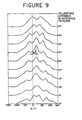
- the output of the digital correlator 43 after digital to analogue conversion is shown in Figure 9, and the corresponding detected flaw pattern is shown in Figure 10.
- the condition of the defect 3 itself is shown in Figures 11 (A) and 11(B).
- the ultrasonic pulses 14a to 17a of the respective channels are overlapped within the material 2, so that significant correlation values appear in several different channels for a single defect 3. Therefore, in such a case, the depth of the reflecting surface of the defect 3 is calculated according to the following equation.
- the signals of the X-Y position of the probe rotating mechanism 7 are fed from the controller 24 through the data selector 46 for storage in the shift register 47 and transferred to the computer through the interface 48 along with the data of the maximum correlation values and the like.
- This data is used on a graphic display to give the position of the defect 3 when the calculated image of the defect is displayed.
- a timing controller 49 is shown in Figure 8. If desired, the probe rotating mechanism 7 may be replaced by electronic scan type probes, but they are too expensive for factory use at the present stage.
- Figure 13 shows the process flow used by the software of the computer 50 during recognition of the shape of the defect 3, in which the components common to Figure 8 are designated by similar reference numerals and their explanations are omitted to avoid repetition.
- the peak values of echoes which are obtained during one revolution through the pulser receivers 25 to 28, analogue peak holding circuits 29 to 32 and analogue to digital converters 33 to 36 according to the rotational angles of the probes 14 to 17 are collected and stored in the memory 51 to form the detected flaw patterns.
- the memory 51 serves as an external memory of the computer 50, and the detected flaw patterns in the memory 51 are transferred by DMA to an internal memory 53 through an interface 52 for the computer 50 before the probes 14 to 17 start to receive ultrasonic pulses from the next revolution.
- the computer 50 includes a CPU 54 (central processing unit), a cathode ray tube 55 for displaying the detected flaw data, and a floppy disk 55 for storing the flaw data.
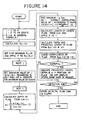
- the computer processes the signals according to the steps shown in the flowchart of Figure 14, in which the detected flaw pattern is indicated by Ai(a).
- the subscripts "i” and “a” indicate the channel and the rotational angle, respectively.
- the reference patterns are indicated by Rj(a) in which the subscript "j” is the inclination of the defect.
- the correlation between Ai(a) and Rj(a) is expressed by the following equation.
- the equation (9) is generally available in the form of a software package.
- the inspection area for the propeller 57 is 1200x800 mm/blade as indicated by a hatched area in Figure 15 and the depth of inspection from the blade surface is 20 mm.
- the cavity defects which may exist in the inspection area 58 only harmful defects are selectively displayed on the CRT (cathode ray tube).
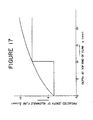
- the degree of severity is judged by the projected length I e in the circumferential direction which is the direction in which the stress is applied. The degree of severity also varies depending upon the depth q of the top end of the defect 3.
- the severity of the defect 3 is defined by the projected length I e of the defect shown in Figures 16(A) and 16(B) and the depth q at the top end of the defect 3 shown in Figure 17. Consequently, the computer 50 performs the following operations in the final processing stage.
- the severity of a defect is defined by two steps in terms of allowable projected dimensions of the defect.
- the computer 50 performs the calculations (10) and (11) as shown in the flowchart of Figure 15, and, if either one of the conditions (12) and (13) is satisfied, displays the calculated image of any harmful defect on the printer along with their positional data.
- Figure 18 shows the relationship between the input voltage of the analogue to digital converter and the number of its effective bits, wherein indicated at (A) is a sufficient input voltage and at (B) an insufficient input voltage, with binary values of 3-bit analogue to digital conversion given on the right side in each case.
- the points which are connected by broken line are the sampled values before analogue to digital conversion.
- the number of effective bits is 3 when the input has a sufficient voltage but it becomes 2 or less when the voltage of the input is insufficient, resulting in a correspondingly lower resolution. Therefore, in order to maximise the resolution of the analogue to digital converter effectively, it is necessary to apply an input voltage which is close to the full scale and, in practical circuits, an amplifier is often inserted in a stage before the analogue to digital converter to adjust the input signal to a level which will ensure the maximum resolution. However, in most cases of non-destructive testing the voltage of the input signal is not known beforehand, so that adjustment of the input signal by an amplifier often leads to trouble such as reduction in the resolution of small signals and too much amplification of large signals.
- the analogue to digital converter should have a high resolution even with regard to input signals of small amplitudes.
- difficulties are often encountered in improving the resolution of the analogue to digital converter due to the limitations which are imposed on the signal processing circuits of subsequent stages.
- Figure 20 illustrates a pre-processing circuit which may be employed in the circuit of Figure 8 to overcome the above-mentioned limitations which is adapted to operate according to the following principles.
- the pre-processing circuit 112 includes analogue to digital converter 113 (corresponding to the analogue to digital converter 33 to 36 of Figure 8), buffer register 114, digital peak hold circuit 115, universal shift register 116, OR gate 117, NAND gate 118, clock generator 119, counter 120 and data selector 121 (corresponding to the data selector 42 in Figure 8).
- the peak hold circuit 111 corresponds to the peak holding circuit 29 of Figure 8.
- the analogue to digital converter 113 of the pre-processing circuit 112 has a 12-bit resolution although a correlator 122 in the previous stage is of 6 bits.
- the maximum values of the input analogue signals are converted into digital quantities with a high resolution of 12 bits to form a detected flaw pattern, the detected flaw pattern is transferred to a succeeding stage separately in the form of significant digits of up to 2 6 and an exponent of 2. More specifically, the detected flaw pattern is temporarily stored in the buffer register 114 of 12 bitsx128, and the maximum value of the transferred detected flaw pattern which consists of 128 points is held in the digital peak hold circuit 115. After the detected flaw pattern is completely stored in the register 114, the maximum value is transferred to the universal shift register 116 which can shift the data to the right and left and up and down. The universal shift register 116 operates in the right-shift mode when it receives the maximum value and then switched to the down-shift mode.
- a down-shift is repeated until data is absent in the upper 6 bits of the universal shift register 116 while confirming the existence of the data in the upper 6 bits of the register by the OR gate 117 and NAND gate 118.
- the number of downshifts is counted by the counter 120.
- the output value of the counter 120 is fed to address pins of the data selector 121, according to which 6 bits are selected from 12-bit output pins of the buffer register 114 by the data selectors 121 so that the significant digits of the maximum value of the detected flaw pattern in the buffer register 114 are expressed by 6 bits or a smaller number of bits.
- the data selector 121 is constituted by six selectors 123 to 128, the input ports of which are connected to the output pins of the buffer register 114 in the positions which are sequentially shifted by one bit.
- the compressed data of the detected flaw pattern which is selected by the data selector 121 is transferred to the correlator 42 for correlation processing as described hereinbefore.
- the significant digits are smaller than 6 bits when the data in the buffer register 114 are smaller than 6 bits.
- the above-described pre-processing circuit 112 permits the execution of the analogue to digital conversion with a high resolution and transfer of the input signal by the maximum number of digits conforming with the resolution of the digital correlator 42 in the subsequent stage.
- FIG 22 there is shown a modification, employing a carriage frame 303 which is driven from a motor 304 and movable back and forth (in Y-axis direction) along rails 304 fixed on the opposite sides of a material 302 under inspection with a cavity internal defect, and a movable frame 305 which is supported on the carriage frame 403 and movable in the transverse direction (X-axis direction).
- a tank 307 accommodates a probe rotating mechanism 309 and receives a supply of a liquid medium 310 in the same manner as in the first embodiment.
- the probe rotating mechanism 309 has a cylindrical shaft 314 which is rotatably supported in a bearing case 313 on a support plate 308, and a probe holder 315 is fixedly mounted at the lower end of the shaft 314 and has four inclined probes 316 to 319 built therein at intervals of 90° in the circumferential direction.
- the probes 316 to 319 have a refraction angle 8 of, for example, 45° and are calibrated to project ultrasonic beams 316a to 319a of 9.2 mm diameter, respectively.
- the probes 316 to 319 are located at different distances from the centre of rotation so that the ultrasonic beams 316a to 319a intersect the axis of rotation at the depths of 2.5 mm, 7.5 mm, 12.5 mm and 17.5 mm, respectively.
- a motor 320 which drives the shaft 314 and a rotary encoder 321 which detects the rotation angle of the probe rotating mechanism 309, are mounted on the support plate 308 and coupled with the shaft 314 through belt driving mechanisms 322 and 323, respectively.
- a system controller 324 consists of a microcomputer, a scan control 325 controls the movements of the probe rotating mechanism 309 in the X- and Y-axes direction, a pulse counter 326, and pulser receivers 327 to 330 are provided for the respective channels and connected to the corresponding probes 316 to 319 through a slip ring 331.
- the probe holder 315 of the probe mechanism 309 is rotated about the shaft 314 and at the same time moved in the X- and Y-axis directions to scan the surface of the material 301, transmitting ultrasonic pulses 16a to 19a from the probes 316 to 319 and picking up the echoes from the defect 302 by the respective channels in the same manner as described hereinbefore.
- the described embodiments of the present invention employ several probes directed at different depths on a rotary mechanism to transmit and receive ultrasonic pulses through a corresponding number of channels, forming a detected flaw pattern from the peak value of the echoes received at the flaw detection gate of each channel.
- the following formula is adopted to estimate the mean depth of a flaw: in which Smi is a maximum value of a detected flaw pattern for each channel.
- flaw size can be estimated by referring to Distance-Amplitude curves and the S'mi value.
- the efficiency of the flaw detection can be improved to a considerable degree since there is no necessity to repeat the inspection of the same portion several times at varied depths as in the conventional flaw detection by a single probe.
- the severity of a detected defect is judged on the basis of the direction, inclination, size and depth of the defect which are decipherable from the correlations of the detected pattern with reference patterns, so that judgement can be made easily and at a high speed by the use of a computer or hard-wired logic circuits, as compared with judgement from the detected flaw pattern itself.
- the resolution of the input signals can be improved remarkably by the provision of the pre-processing circuit which employs an analogue to digital converter of high resolution and which is adapted to transfer the converted digital signals by a bit number conforming with the resolution of the correlator of the subsequent stage of the circuit.
- the output signals to the recorders 219, 336 are preferably passed to a correlation system such as is described with reference to the embodiment of Figure 5 and in particular with reference to Figure 8.
- the signals passed to the pen recorders 219, 336 may be passed to apparatus including the data selector 42, the digital correlator 43, memory 41, digital peak detector 44, data latch 45, shift register 47 and interface 48.
- the signals may also be pre-processed in the manner described hereinbefore with reference to Figure 20.
Landscapes
- Physics & Mathematics (AREA)
- Biochemistry (AREA)
- Health & Medical Sciences (AREA)
- Life Sciences & Earth Sciences (AREA)
- Chemical & Material Sciences (AREA)
- Analytical Chemistry (AREA)
- General Health & Medical Sciences (AREA)
- General Physics & Mathematics (AREA)
- Immunology (AREA)
- Pathology (AREA)
- Acoustics & Sound (AREA)
- Engineering & Computer Science (AREA)
- Signal Processing (AREA)
- Investigating Or Analyzing Materials By The Use Of Ultrasonic Waves (AREA)
Claims (6)
Applications Claiming Priority (8)
| Application Number | Priority Date | Filing Date | Title |
|---|---|---|---|
| JP127184/82 | 1982-07-20 | ||
| JP127183/82 | 1982-07-20 | ||
| JP57127183A JPS5917698A (ja) | 1982-07-20 | 1982-07-20 | デイジタル信号処理のための前処理回路 |
| JP127186/82 | 1982-07-20 | ||
| JP127185/82 | 1982-07-20 | ||
| JP57127186A JPS5917156A (ja) | 1982-07-20 | 1982-07-20 | 超音波法による欠陥の検出方法 |
| JP57127184A JPS5917154A (ja) | 1982-07-20 | 1982-07-20 | 超音波法による欠陥の検出方法 |
| JP57127185A JPS5917155A (ja) | 1982-07-20 | 1982-07-20 | 超音波法による欠陥の検出方法 |
Publications (2)
| Publication Number | Publication Date |
|---|---|
| EP0102176A1 EP0102176A1 (de) | 1984-03-07 |
| EP0102176B1 true EP0102176B1 (de) | 1987-09-16 |
Family
ID=27471279
Family Applications (1)
| Application Number | Title | Priority Date | Filing Date |
|---|---|---|---|
| EP83304211A Expired EP0102176B1 (de) | 1982-07-20 | 1983-07-20 | Verfahren und Vorrichtung zur Ultraschallfehlerprüfung |
Country Status (3)
| Country | Link |
|---|---|
| US (1) | US4524622A (de) |
| EP (1) | EP0102176B1 (de) |
| DE (1) | DE3373709D1 (de) |
Families Citing this family (26)
| Publication number | Priority date | Publication date | Assignee | Title |
|---|---|---|---|---|
| DE3314181A1 (de) * | 1983-04-19 | 1984-10-25 | Kraftwerk Union AG, 4330 Mülheim | Verfahren zur ueberwachung der ermuedung von bauteilen, z.b. in kernkraftwerken |
| GB8317247D0 (en) * | 1983-06-24 | 1983-07-27 | Atomic Energy Authority Uk | Ultrasonic scanning probe |
| DE3416709A1 (de) * | 1984-05-05 | 1985-11-07 | Nukem Gmbh, 6450 Hanau | Verfahren zur zerstoerungsfreien pruefung von werkstuecken oder bauteilen mit ultraschall und vorrichtung zur durchfuehrung des verfahrens |
| FR2564202A1 (fr) * | 1984-05-10 | 1985-11-15 | Ledieu Joel | Procede et installation de detection et de controle de la profondeur de fissures dans des pieces en service, notamment de fissures de moyeux de roues |
| DE3577002D1 (de) * | 1985-04-22 | 1990-05-10 | Hitachi Construction Machinery | Messverfahren des neigungswinkels eines risses auf der oberflaeche in einem erzeugnis mittels ultraschall. |
| US4712722A (en) * | 1985-09-04 | 1987-12-15 | Eg&G, Inc. | Concurrent ultrasonic weld evaluation system |
| US4799168A (en) * | 1985-12-31 | 1989-01-17 | The Boeing Company | Data recording apparatus for an ultrasonic inspection system |
| US4799177A (en) * | 1985-12-31 | 1989-01-17 | The Boeing Company | Ultrasonic instrumentation for examination of variable-thickness objects |
| FR2615288B1 (fr) * | 1987-05-12 | 1989-09-22 | Commissariat Energie Atomique | Procede automatique d'identification de defauts par ultrasons et systeme correspondant |
| FR2662501B1 (fr) * | 1990-05-28 | 1994-11-18 | Valtubes | Procede de detection de defauts sur des tubes metalliques a nervures helicouidales internes. |
| GB2254426B (en) * | 1991-04-03 | 1995-06-14 | Honda Motor Co Ltd | Method of and apparatus for detecting defects in an object |
| DE4213139A1 (de) * | 1992-04-22 | 1993-06-09 | Siemens Ag, 8000 Muenchen, De | Verfahren und anordnung zur ultraschallpruefung eines zylindrischen koerpers |
| US5465724A (en) * | 1993-05-28 | 1995-11-14 | Acuson Corporation | Compact rotationally steerable ultrasound transducer |
| GB2280507A (en) * | 1993-07-31 | 1995-02-01 | Alexander Rankin Cornforth | SCAN - Method and apparatus for ultrasonic testing of tubular products. |
| US6487909B2 (en) * | 2001-02-05 | 2002-12-03 | Siemens Westinghouse Power Corporation | Acoustic waveguide sensing the condition of components within gas turbines |
| US6772636B2 (en) * | 2002-11-06 | 2004-08-10 | Varco I/P, Inc. | Pipe flaw detector |
| GB2402483B (en) * | 2003-06-07 | 2006-12-27 | Phoenix Inspection Systems Ltd | Ultrasonic inspection apparatus and method of using same for defect detection and/or direction finding |
| US7430913B2 (en) * | 2005-08-26 | 2008-10-07 | The Boeing Company | Rapid prototype integrated matrix ultrasonic transducer array inspection apparatus, systems, and methods |
| SG138524A1 (en) | 2006-06-22 | 2008-01-28 | Siltronic Ag | Method and apparatus for detection of mechanical defects in an ingot piece composed of semiconductor material |
| JP4910770B2 (ja) * | 2007-02-28 | 2012-04-04 | Jfeスチール株式会社 | 管体の超音波探傷装置および超音波探傷方法 |
| JP5094963B2 (ja) * | 2007-05-15 | 2012-12-12 | シーメンス アクチエンゲゼルシヤフト | 超音波を用いた検査対象の非破壊材料検査方法および装置 |
| JP4686648B1 (ja) * | 2010-09-02 | 2011-05-25 | 株式会社日立製作所 | 超音波検査方法 |
| DE102010040856A1 (de) * | 2010-09-16 | 2012-03-22 | Siemens Aktiengesellschaft | Verfahren und Vorrichtung zur Ermittlung einer Orientierung eines innerhalb eines mechanischen Bauteils bestehenden Defektes |
| CN103969330B (zh) * | 2014-04-28 | 2016-08-17 | 河海大学常州校区 | 一种管道内部缺陷超声探伤装置 |
| CN114679286A (zh) * | 2020-12-24 | 2022-06-28 | 南京众城亿轮轨道交通技术有限公司 | 一种用于空心轴超声波探伤数据加密方法 |
| CN116124885A (zh) * | 2022-08-31 | 2023-05-16 | 杭州赛弗无损检测技术有限公司 | 一种金属件超声无损快速检测方法 |
Family Cites Families (7)
| Publication number | Priority date | Publication date | Assignee | Title |
|---|---|---|---|---|
| US3280621A (en) * | 1963-10-28 | 1966-10-25 | Louis C Cardinal | Omni-directional ultrasonic search unit |
| SU406156A1 (de) * | 1972-01-28 | 1973-11-05 | ||
| DE2260932C3 (de) * | 1972-12-08 | 1979-05-23 | Kraftwerk Union Ag, 4330 Muelheim | Verfahren zum Bestimmen der RiBtiefe von in Werkstücken auftretenden Rissen |
| US3977236A (en) * | 1974-10-21 | 1976-08-31 | The Boeing Company | Apparatus and method for ultrasonic fastener hole inspection |
| JPS5713352A (en) * | 1980-06-30 | 1982-01-23 | Suzukou Shoji Kk | Probe holder for ultrasonic flaw detector |
| NL8102104A (nl) * | 1981-04-29 | 1982-11-16 | Philips Nv | Inrichting voor onderzoek met behulp van ultrageluidsgolven. |
| US4402223A (en) * | 1981-08-07 | 1983-09-06 | General Electric Company | Ultrasonic sector scanner utilizing rotating transducer |
-
1983
- 1983-07-18 US US06/514,864 patent/US4524622A/en not_active Expired - Fee Related
- 1983-07-20 DE DE8383304211T patent/DE3373709D1/de not_active Expired
- 1983-07-20 EP EP83304211A patent/EP0102176B1/de not_active Expired
Also Published As
| Publication number | Publication date |
|---|---|
| EP0102176A1 (de) | 1984-03-07 |
| US4524622A (en) | 1985-06-25 |
| DE3373709D1 (en) | 1987-10-22 |
Similar Documents
| Publication | Publication Date | Title |
|---|---|---|
| US4524622A (en) | Method and apparatus of ultrasonic flaw detection | |
| US9188567B2 (en) | Ultrasonic inspection method | |
| US4843884A (en) | Method and system for ultrasonic detection of flaws in test objects | |
| EP0829714A1 (de) | Ultraschallfehlerdetektor und ultraschallverfahren zum erkennen von fehlern | |
| EP0642015A1 (de) | Verfahren und Vorrichtung zur Messung und Regelung der refraktierten Winkel von Ultraschallwellen | |
| AU2005325873B2 (en) | Method and device for determining defects on a component of a turbine | |
| GB1559469A (en) | Method and apparatus for automatic ultrasonic flaw detection | |
| KR20220004184A (ko) | 초음파 탐상 방법, 초음파 탐상 장치, 강재의 제조 설비 열, 강재의 제조 방법, 및 강재의 품질 보증 방법 | |
| US5426978A (en) | Non-destructive axle flaw detecting apparatus | |
| US4869109A (en) | Automatic process for identification of defects by ultrasound and corresponding system | |
| US5513532A (en) | Method and apparatus for detecting internal defects | |
| US5280723A (en) | Apparatus and method for data acquisition and processing | |
| US4709582A (en) | Inspection device for rotor binding defects in electrical machines | |
| JPH0245823B2 (de) | ||
| JPH07244028A (ja) | 球状被検体の超音波探傷装置およびその方法 | |
| JP7294283B2 (ja) | 超音波探傷方法、超音波探傷装置、及び鋼材の製造方法 | |
| KR100497501B1 (ko) | 초음파를 이용한 자동차 엔진용 피스톤 갤러리의 결함탐지방법 및 이에 사용되는 결함탐지 장치 | |
| SU1293630A1 (ru) | Способ ультразвукового контрол изделий | |
| CN118392991B (zh) | 基于图像的圆柱型物件检测方法 | |
| CN113899785A (zh) | 一种基于超声和红外探伤对锂电池的检测方法 | |
| GB2169102A (en) | Non-destructive testing | |
| JPH01299456A (ja) | 超音波探傷装置 | |
| JPS6080761A (ja) | 超音波診断装置 | |
| Poulter | Signal processing methods applied in the ultrasonic inspection of PWR inlet nozzles | |
| Schmitz et al. | Practical experiences with LSAFT |
Legal Events
| Date | Code | Title | Description |
|---|---|---|---|
| PUAI | Public reference made under article 153(3) epc to a published international application that has entered the european phase |
Free format text: ORIGINAL CODE: 0009012 |
|
| 17P | Request for examination filed |
Effective date: 19830730 |
|
| AK | Designated contracting states |
Designated state(s): DE GB NL |
|
| GRAA | (expected) grant |
Free format text: ORIGINAL CODE: 0009210 |
|
| AK | Designated contracting states |
Kind code of ref document: B1 Designated state(s): DE GB NL |
|
| REF | Corresponds to: |
Ref document number: 3373709 Country of ref document: DE Date of ref document: 19871022 |
|
| PLBE | No opposition filed within time limit |
Free format text: ORIGINAL CODE: 0009261 |
|
| STAA | Information on the status of an ep patent application or granted ep patent |
Free format text: STATUS: NO OPPOSITION FILED WITHIN TIME LIMIT |
|
| 26N | No opposition filed | ||
| PGFP | Annual fee paid to national office [announced via postgrant information from national office to epo] |
Ref country code: GB Payment date: 19900709 Year of fee payment: 8 |
|
| PGFP | Annual fee paid to national office [announced via postgrant information from national office to epo] |
Ref country code: NL Payment date: 19900731 Year of fee payment: 8 |
|
| PGFP | Annual fee paid to national office [announced via postgrant information from national office to epo] |
Ref country code: DE Payment date: 19900831 Year of fee payment: 8 |
|
| PG25 | Lapsed in a contracting state [announced via postgrant information from national office to epo] |
Ref country code: GB Effective date: 19910720 |
|
| PG25 | Lapsed in a contracting state [announced via postgrant information from national office to epo] |
Ref country code: NL Effective date: 19920201 |
|
| NLV4 | Nl: lapsed or anulled due to non-payment of the annual fee | ||
| GBPC | Gb: european patent ceased through non-payment of renewal fee | ||
| PG25 | Lapsed in a contracting state [announced via postgrant information from national office to epo] |
Ref country code: DE Effective date: 19920401 |