EP0102244A2 - Unité d'entraînement pour bateaux à transmission en z - Google Patents
Unité d'entraînement pour bateaux à transmission en z Download PDFInfo
- Publication number
- EP0102244A2 EP0102244A2 EP83304944A EP83304944A EP0102244A2 EP 0102244 A2 EP0102244 A2 EP 0102244A2 EP 83304944 A EP83304944 A EP 83304944A EP 83304944 A EP83304944 A EP 83304944A EP 0102244 A2 EP0102244 A2 EP 0102244A2
- Authority
- EP
- European Patent Office
- Prior art keywords
- drive unit
- transom
- gear box
- casing
- transmission casing
- Prior art date
- Legal status (The legal status is an assumption and is not a legal conclusion. Google has not performed a legal analysis and makes no representation as to the accuracy of the status listed.)
- Withdrawn
Links
Images

Classifications
-
- B—PERFORMING OPERATIONS; TRANSPORTING
- B63—SHIPS OR OTHER WATERBORNE VESSELS; RELATED EQUIPMENT
- B63H—MARINE PROPULSION OR STEERING
- B63H20/00—Outboard propulsion units, e.g. outboard motors or Z-drives; Arrangements thereof on vessels
- B63H20/14—Transmission between propulsion power unit and propulsion element
- B63H20/22—Transmission between propulsion power unit and propulsion element allowing movement of the propulsion element about at least a horizontal axis without disconnection of the drive, e.g. using universal joints
-
- B—PERFORMING OPERATIONS; TRANSPORTING
- B63—SHIPS OR OTHER WATERBORNE VESSELS; RELATED EQUIPMENT
- B63H—MARINE PROPULSION OR STEERING
- B63H20/00—Outboard propulsion units, e.g. outboard motors or Z-drives; Arrangements thereof on vessels
- B63H20/08—Means enabling movement of the position of the propulsion element, e.g. for trim, tilt or steering; Control of trim or tilt
- B63H20/10—Means enabling trim or tilt, or lifting of the propulsion element when an obstruction is hit; Control of trim or tilt
-
- B—PERFORMING OPERATIONS; TRANSPORTING
- B63—SHIPS OR OTHER WATERBORNE VESSELS; RELATED EQUIPMENT
- B63H—MARINE PROPULSION OR STEERING
- B63H20/00—Outboard propulsion units, e.g. outboard motors or Z-drives; Arrangements thereof on vessels
- B63H20/08—Means enabling movement of the position of the propulsion element, e.g. for trim, tilt or steering; Control of trim or tilt
- B63H20/12—Means enabling steering
-
- B—PERFORMING OPERATIONS; TRANSPORTING
- B63—SHIPS OR OTHER WATERBORNE VESSELS; RELATED EQUIPMENT
- B63H—MARINE PROPULSION OR STEERING
- B63H20/00—Outboard propulsion units, e.g. outboard motors or Z-drives; Arrangements thereof on vessels
- B63H20/14—Transmission between propulsion power unit and propulsion element
- B63H20/20—Transmission between propulsion power unit and propulsion element with provision for reverse drive
-
- B—PERFORMING OPERATIONS; TRANSPORTING
- B63—SHIPS OR OTHER WATERBORNE VESSELS; RELATED EQUIPMENT
- B63H—MARINE PROPULSION OR STEERING
- B63H20/00—Outboard propulsion units, e.g. outboard motors or Z-drives; Arrangements thereof on vessels
- B63H20/24—Arrangements, apparatus and methods for handling exhaust gas in outboard drives, e.g. exhaust gas outlets
- B63H20/245—Exhaust gas outlets
Definitions
- the present invention relates to stern or inboard/outboard drive units for boats.
- the propellor is usually mounted at the lower end of a generally upright transmission casing or "leg" which, in use, is carried by, and located outboard of, the boat hull at the stern thereof.
- Propulsive power is transmitted down the leg to the propellor from an inboard motor unit coupled to the upper end of the leg.
- the leg is attached to a transom plate or other mounting means, by which the drive unit is mounted on the hull transom, by an articulated mounting which permits the leg to turn about a generally upright axis for the purpose of steering, and to tilt about a generally transverse axis to permit trim adjustment and/or the raising or lowering of the propellor.
- a transom plate or other mounting means by which the drive unit is mounted on the hull transom, by an articulated mounting which permits the leg to turn about a generally upright axis for the purpose of steering, and to tilt about a generally transverse axis to permit trim adjustment and/or the raising or lowering of the propellor.
- a transmission device comprising a gear box providing for selection of forward or reverse drive is incorporated either in the upper or lower end of the leg, or is mounted inboard of the hull, spaced forwardly of the transom.
- a stern drive unit of the type specified including a transmission device, providing for selection of forward or reverse drive, and/or for a change in transmission ratio, the transmission device being rigid with the transom plate or other drive unit mounting or bearer means.
- the transmission device comprises a gear box providing for selection of forward or reverse drive.
- the gear box includes a casing which is rigid with the transom plate, the gear box being so positioned that, when the transom plate is operatively mounted on a hull transan, it is disposed at least partially outboard of the hull.
- the casing may be separate from, and attached to, the transom plate, or preferably, if the transom plate is a casting, the gear box casing may be cast integrally with the transom plate.
- the gear box casing may include a plate or plates, disposed outboard of the transom plate, through which the gear mechanism may be assembled within or removed from the casing, and/or may be accessible, for example for maintenance purposes.
- the transom 1 and bottom 2 of the stern region of a boat hull mounteded from the transom 1 is an outboard drive unit 3 of the stern or inboard/ outboard drive type, which is coupled via a gear box 5 to an inboard motor unit (not shown), for example a petrol or disel internal combustion engine.
- the unit 3 includes a bearer or transom plate 4 bolted or otherwise secured to the outboard face of the transom 1, extending across openings la and lb in the transom.
- the transom plate 4 is cast from a light metal alloy integrally with the portion 5a of the gear box housing or casing projecting outboard of the transom plate, and also with an inboard casing portion 5b which projects through the lower opening lb in the transom.
- the casing portion 5b receives a drive shaft 6, rotatable about a generally horizontal axis, connected at its left hand end to the engine crank shaft via a shaft 7a and a flexible joint 7b.
- a splined connection may be provided between the shaft 6 and/or 7a and the flexible joint 7b.
- the gear box input shaft 6 is connected, within the casing 5a, to a gear mechanism (not shown) coupled to a gear box output shaft rotatable about a dropped axis 8, so as to permit the gear box output shaft to be rotated, selectively, in a forward or reverse direction relative to the input shaft, optionally with a ratio change.
- the gear mechanism may include dog clutches which not only enable gear change, but also provide a neutral position.
- the gear mechanism may, for example, be of the type described in my British Patent Application No: 7937746 (Publication No: 2062135).
- the gear box output shaft is connected, via an articulated or universal joint positioned in a boot or gaiter 9, to an input shaft mounted at the upper end of a generally upright elongate transmission casing or leg 10.
- the gaiter 9 bridges a tubular rearward extension 5c, of the wall 5c of the gear box and a tubular forward extension or bell housing 10a at the upper end of the leg 10.
- the input shaft to the leg 10 is drivingly connected, internally of the leg 10, to a propellor shaft 11 by any appropriate transmission so as, in operation, to rotate the propellor shaft and propellor (not shown) mounted thereon.
- the input shaft may, for example, be coupled to the propellor shaft by a gear mechanism of the type disclosed in my British Patent No: 1,529,459.
- the rearwardly directed wall 5c of the gear box casing is wholly or partly detachable to enable the gear mechanism to be assembled in or removed from the gear box 5, and to provide access for servicing and maintenance, and/or exchange of ratios.
- the opposite internal end wall of the gear box casing, which in this embodiment is just outboard of the transom plate, is preferably formed integrally with the casing and transom plate.
- the leg 10 which depends from the lower end of the gear box 5, is attached to the gear box casing 5a, and/or to the transom plate 4, by articulated mounting means comprising a stirrup or yoke 12 which bridges and embraces the upper end of the leg.
- the leg is mounted for pivotal movement about a generally horizontal transverse axis 13 relative to the yoke 12.
- the yoke is mounted at the lower end of a steering shaft 14 mounted for turning movement about an inclined axis 15 in bosses 4a and 5d integral with the transom plate 4 and gear box casing rear wall 5c, respectively.
- the inboard upper end portion of the steering shaft comprises a tubular cranked extension 14a, to the upper end of which is secured a steering arm 14b, so that turning of the arm 14b will turn the shaft 14 and therefore the leg 10 about the axis 15 for steering purposes.
- the pivotal mounting of the leg 10 to the yoke 12 allows the leg to be tilted about the axis 13 by means, for example of atrim/tilt shaft 16 comprising a straight rod or tube, hinged at 16a, the lower end of which is pivotally connected at 16b to the rear of the top of the leg 10.
- the shaft 16 pases slidably upwardly into and through the inboard tubular extension 14a of the steering shaft.
- the axis of the trim/tilt shaft 16 and tubular extension 14a is inclined relative to the axis 15 of the steering shaft.
- the upper end of the trim/tilt shaft 16 carries a manual operating handle 17 to permit axial adjustment of the shaft 16, and therefore trim/tilt adjustment of the leg 10 of the outboard unit 3, and a releasable locking arrangement is provided to permit the shaft to be locked in its adjusted position.
- the locking arrangement comprises a collet arrangement 18 including a collet body (not shown) mounted on the end of the extension 14a.
- the collet body is axially split to form a series of tapered collet segments disposed around the shaft 16, and is located within a correspondingly internally tapered lock nut 18a threaded onto the collet body.
- the leg may also be raised from the position shown in full lines to the position shown in broken lines in Figure 1 when the unit is not in use, by means of the lifting handle.
- the articulated or gimbal mounting of the leg 10 is so arranged that the horizontal tilt axis 13, and the steering axis 15 intersect generally at the center of the universal or constant velocity joint coupling the gear box output shaft to the leg input shaft, which is coincedent with the axis 8, so as to avoid the necessity for compensating for bodily movement, as distinct from pivotal movement, between the latter shafts.
- the axes of the steering shaft 14 and of the trim/tilt shaft 16 advantageously intersect at the location of the top bearing or boss 4a.
- the extent of the pivotal movement of the leg relative to the trim gear box in the steering and/or tilt directions may be limited by engagement of the tubular extensions 5c' and 10a of the gear box and leg.
- the gear box casing portion 5b incorporates, in its lower part 5e, an inlet duct (not shown) which, in operation, is connected to the exhaust manifold of the engine.
- the latter duct extends within the casing portion 5b, through the transom and transom plate, and around and below the gear mechanism in the casing 5a.
- the portion of the exhaust duct outboard of the transom plate may be formed integrally with the lower part 5f of the gear box casing, or may comprise a separate pipe attached thereto.
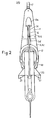
- the aft end 19 of the exhaust duct is slidably received in a socket 20 fixed to or integral with the casing of the leg 10, the socket communicating with a duct terminating in rearwardly opening exhaust outlets 21 ( Figure 2) forming part of the cavitation plate 22 of the leg.
- the socket 20, and aft end 19 of the duct are so configured as to allow tilting and turning of the leg, and therefore of the socket 20 relative to the end 19 of the duct, during normal running of the drive unit, but to allow the socket 20 to slide off the end 19 of the duct when the leg is raised.
- Sealing means may be provided, for example a nylon brush-type seal or equivalent, to reduce or minimise exhaust gas leakage between the socket 20 and duct end 19 when interengaged.
- the aft end 19 of the duct, and also the exhaust outlet 21 of the duct, will normally be submerged, or at least partially submerged,to reduce exhaust noise and fumes.
- the duct and in particular the outlet 21, may alternatively be formed within, instead of below,the cavitation plate 22.
- the casing portion 5b also includes a duct (not shown) connected to an outboard water pick-up tube 23, the duct being connected to the cooling water inlet of the engine. This water, after circulation is mixed with the engine exhaust and is discharged therewith via the exhaust duct arrangement 19, 20 and 21.
- a frame (not shown) is mounted on the gear box casing portion 5b inboard of the transom, which carries at least the rear upper bearer(s) or mounting(s) for the inboard engine.
- the frame also includes the connections to the exhaust and water ducts in the casing portion 5b, and to the gear selectors in the gear box.
- the stern drive unit hereinbefore described possesses numerous advantages.
- the gear box casing, or a significant part thereof, may readily be cast integrally with the transom plate or equivalent.
- the problems and restraints associated with a separate inboard-mounted gear box are eliminated, as are the problems and restraints associated with gear boxes when incorporated in the upper or lower ends of the leg. Since the gear box is positioned, or projects,outboard of the transom, it is readily accessible, should the need arise, for maintenance or repair, as well as for assembly or disassembly, ratio changes, etc. Since the gear box is mounted towards the bottom of the transom, it will normally be submerged or partially submerged, or sprayed, which enhances cooling. Even if mounted above the water line, the gear box will still be subjected to efficient air cooling.
- the gear box could be mounted wholly inboard, or partly inboard and partly outboard, of the transom plate or other bearer arrangement.
- the gear box may incorporate a clutch mechanism other than dog clutches, although this mechanism could alternatively be associated with the engine.
- the gear box could provide a ratio change.
- a change ratio gear box or the like could be provided between the transom-mounted gear box and the engine.
- the gear box casing is attached to or integral with the transom plate
- the drive could extend through the bottom of the boat hull instead of the transom, in which event the gear box casing could be combined with an equivalent plate or other means by which the drive unit is secured to the bottom of the hull.
- the trim/tilt arrangement may take other forms, for example the shaft arrangement 16 may be replaced by a cable or the like.
- the arrangement 16 possesses the advantage that it is rigid, and will act not only as a tie to prevent clockwise tilting of the leg 10 as viewed in Figure 1 when the propellor is driving the boat forwards, but also as a strut to prevent anticlockwise tilting of the leg under the influence of reverse thrust.
- the collet arrangement may be replaced by other locking arrangements, for example a ratchet and paul arrangement, or an arrangement using a locking pin insertable in a selected one of a 'longitudinal row of transverse openings in the shaft arrangement 16 or equivalent at/or adjacent its upper end.
- tilting or trimming, and raising and lowering, of the leg may be readily effected manually, hydraulic or electrical power tilt and lift mechanisms could be provided. Such mechanisms could be employed to operate, or assist in operating the trim/tilt arrangements, and/or steering arrangements, herein described,although they could alternatively replace such arrangements.
- the particular relatively simple and effective tilting mechanism, lifting mechanism, and/or steering mechanism, and/or the relatively simple and effective split exhaust system may be used with other types of stern drive units, i.e. units which do not incorporate a transom-mounted gear box.
Landscapes
- Chemical & Material Sciences (AREA)
- Engineering & Computer Science (AREA)
- Combustion & Propulsion (AREA)
- Mechanical Engineering (AREA)
- Ocean & Marine Engineering (AREA)
- Gear Transmission (AREA)
- Connection Of Motors, Electrical Generators, Mechanical Devices, And The Like (AREA)
Applications Claiming Priority (4)
| Application Number | Priority Date | Filing Date | Title |
|---|---|---|---|
| GB8224691 | 1982-08-27 | ||
| GB8224691 | 1982-08-27 | ||
| GB8300184 | 1983-01-05 | ||
| GB838300184A GB8300184D0 (en) | 1983-01-05 | 1983-01-05 | Stern drive unit for boats |
Publications (2)
| Publication Number | Publication Date |
|---|---|
| EP0102244A2 true EP0102244A2 (fr) | 1984-03-07 |
| EP0102244A3 EP0102244A3 (fr) | 1985-05-15 |
Family
ID=26283688
Family Applications (1)
| Application Number | Title | Priority Date | Filing Date |
|---|---|---|---|
| EP83304944A Withdrawn EP0102244A3 (fr) | 1982-08-27 | 1983-08-26 | Unité d'entraínement pour bateaux à transmission en z |
Country Status (1)
| Country | Link |
|---|---|
| EP (1) | EP0102244A3 (fr) |
Cited By (1)
| Publication number | Priority date | Publication date | Assignee | Title |
|---|---|---|---|---|
| CN102011622A (zh) * | 2009-09-07 | 2011-04-13 | 上海尤顺汽车部件有限公司 | 一种改进的发动机制动的驱动装置 |
Family Cites Families (4)
| Publication number | Priority date | Publication date | Assignee | Title |
|---|---|---|---|---|
| CH158426A (fr) * | 1931-10-07 | 1932-11-15 | Moser Fritz | Bateua à hélice. |
| US4178873A (en) * | 1978-02-06 | 1979-12-18 | Brunswick Corporation | Exhaust coupling assembly for a marine stern drive |
| GB2062135A (en) * | 1979-10-31 | 1981-05-20 | Brown W | Reversible transmission devices |
| US4565532A (en) * | 1981-02-18 | 1986-01-21 | Kaama Marine Engineering, Inc. | Stern drive |
-
1983
- 1983-08-26 EP EP83304944A patent/EP0102244A3/fr not_active Withdrawn
Cited By (1)
| Publication number | Priority date | Publication date | Assignee | Title |
|---|---|---|---|---|
| CN102011622A (zh) * | 2009-09-07 | 2011-04-13 | 上海尤顺汽车部件有限公司 | 一种改进的发动机制动的驱动装置 |
Also Published As
| Publication number | Publication date |
|---|---|
| EP0102244A3 (fr) | 1985-05-15 |
Similar Documents
| Publication | Publication Date | Title |
|---|---|---|
| US4371348A (en) | Mounting for marine propulsion device located aft of boat transom | |
| US3006311A (en) | Boat steering means including a swingable and tiltable outboard unit | |
| US4545770A (en) | Outboard motor mounting arrangement | |
| US3336752A (en) | Jet boat propulsion unit | |
| US4565532A (en) | Stern drive | |
| US5108325A (en) | Boat propulsion device | |
| US4911666A (en) | Boat propulsion device with internal exhaust | |
| US6280267B1 (en) | Retractable trolling motor | |
| CA1312504C (fr) | Propulseur en l | |
| US4600395A (en) | Boat drive | |
| US3893407A (en) | Inboard-outboard marine drive | |
| CA1182001A (fr) | Moteur a vilebrequin vertical avec gouvernail et carter d'helice relevables monte sur arcasse d'embarcation | |
| US4565534A (en) | Water pump location for marine propulsion device | |
| US4493662A (en) | Shaft connecting device for boat propellers | |
| EP0102244A2 (fr) | Unité d'entraînement pour bateaux à transmission en z | |
| US3587510A (en) | Marine propulsion device with split drive shaft | |
| US4654013A (en) | Steering means for marine propulsion device | |
| US4927391A (en) | Shift means for marine propulsion device | |
| AU605765B2 (en) | Outboard motor mounting arrangement | |
| US3136282A (en) | Steering arrangement for inboardoutboard drive | |
| KR100300565B1 (ko) | 선박추진장치 | |
| US5203730A (en) | Tilting system for outboard drive unit | |
| DK0535100T3 (da) | Indretning til et svingbart, opvippeligt indenbords/udenbords agterstavnsaggregat til en båd | |
| CA1313797C (fr) | Logement d'arbre de transmission et tuyau interne d'echappement pour propulseur marin | |
| AU619189B2 (en) | Boat propulsion device |
Legal Events
| Date | Code | Title | Description |
|---|---|---|---|
| PUAI | Public reference made under article 153(3) epc to a published international application that has entered the european phase |
Free format text: ORIGINAL CODE: 0009012 |
|
| AK | Designated contracting states |
Designated state(s): AT BE CH DE FR GB IT LI LU NL SE |
|
| PUAL | Search report despatched |
Free format text: ORIGINAL CODE: 0009013 |
|
| AK | Designated contracting states |
Designated state(s): AT BE CH DE FR GB IT LI LU NL SE |
|
| STAA | Information on the status of an ep patent application or granted ep patent |
Free format text: STATUS: THE APPLICATION IS DEEMED TO BE WITHDRAWN |
|
| 18D | Application deemed to be withdrawn |
Effective date: 19860116 |