EP0102273A1 - Zünd- und Einspritzungssteueranlage für eine Brennkraftmaschine - Google Patents
Zünd- und Einspritzungssteueranlage für eine Brennkraftmaschine Download PDFInfo
- Publication number
- EP0102273A1 EP0102273A1 EP83401543A EP83401543A EP0102273A1 EP 0102273 A1 EP0102273 A1 EP 0102273A1 EP 83401543 A EP83401543 A EP 83401543A EP 83401543 A EP83401543 A EP 83401543A EP 0102273 A1 EP0102273 A1 EP 0102273A1
- Authority
- EP
- European Patent Office
- Prior art keywords
- computer
- ignition
- signal
- angle
- advance
- Prior art date
- Legal status (The legal status is an assumption and is not a legal conclusion. Google has not performed a legal analysis and makes no representation as to the accuracy of the status listed.)
- Granted
Links
- 238000002347 injection Methods 0.000 title claims abstract description 24
- 239000007924 injection Substances 0.000 title claims abstract description 24
- 238000002485 combustion reaction Methods 0.000 title claims description 8
- 239000000446 fuel Substances 0.000 title claims description 5
- 238000004364 calculation method Methods 0.000 claims description 17
- 238000012937 correction Methods 0.000 claims description 14
- 230000006870 function Effects 0.000 claims description 8
- 230000015654 memory Effects 0.000 claims description 7
- 239000000243 solution Substances 0.000 description 6
- 238000004519 manufacturing process Methods 0.000 description 4
- 230000001133 acceleration Effects 0.000 description 3
- 238000000034 method Methods 0.000 description 3
- 238000012545 processing Methods 0.000 description 3
- 239000004020 conductor Substances 0.000 description 2
- 238000005259 measurement Methods 0.000 description 2
- 238000004804 winding Methods 0.000 description 2
- 238000009530 blood pressure measurement Methods 0.000 description 1
- 239000003795 chemical substances by application Substances 0.000 description 1
- 238000004891 communication Methods 0.000 description 1
- 238000011161 development Methods 0.000 description 1
- 238000004880 explosion Methods 0.000 description 1
- 239000000203 mixture Substances 0.000 description 1
- 238000012986 modification Methods 0.000 description 1
- 230000004048 modification Effects 0.000 description 1
- 230000007935 neutral effect Effects 0.000 description 1
- 238000007493 shaping process Methods 0.000 description 1
- 230000001360 synchronised effect Effects 0.000 description 1
Images
Classifications
-
- F—MECHANICAL ENGINEERING; LIGHTING; HEATING; WEAPONS; BLASTING
- F02—COMBUSTION ENGINES; HOT-GAS OR COMBUSTION-PRODUCT ENGINE PLANTS
- F02P—IGNITION, OTHER THAN COMPRESSION IGNITION, FOR INTERNAL-COMBUSTION ENGINES; TESTING OF IGNITION TIMING IN COMPRESSION-IGNITION ENGINES
- F02P5/00—Advancing or retarding ignition; Control therefor
- F02P5/04—Advancing or retarding ignition; Control therefor automatically, as a function of the working conditions of the engine or vehicle or of the atmospheric conditions
- F02P5/145—Advancing or retarding ignition; Control therefor automatically, as a function of the working conditions of the engine or vehicle or of the atmospheric conditions using electrical means
- F02P5/15—Digital data processing
- F02P5/1518—Digital data processing using two or more central computing units, e.g. interpolation
-
- F—MECHANICAL ENGINEERING; LIGHTING; HEATING; WEAPONS; BLASTING
- F02—COMBUSTION ENGINES; HOT-GAS OR COMBUSTION-PRODUCT ENGINE PLANTS
- F02D—CONTROLLING COMBUSTION ENGINES
- F02D41/00—Electrical control of supply of combustible mixture or its constituents
- F02D41/24—Electrical control of supply of combustible mixture or its constituents characterised by the use of digital means
- F02D41/26—Electrical control of supply of combustible mixture or its constituents characterised by the use of digital means using computer, e.g. microprocessor
- F02D41/266—Electrical control of supply of combustible mixture or its constituents characterised by the use of digital means using computer, e.g. microprocessor the computer being backed-up or assisted by another circuit, e.g. analogue
-
- Y—GENERAL TAGGING OF NEW TECHNOLOGICAL DEVELOPMENTS; GENERAL TAGGING OF CROSS-SECTIONAL TECHNOLOGIES SPANNING OVER SEVERAL SECTIONS OF THE IPC; TECHNICAL SUBJECTS COVERED BY FORMER USPC CROSS-REFERENCE ART COLLECTIONS [XRACs] AND DIGESTS
- Y02—TECHNOLOGIES OR APPLICATIONS FOR MITIGATION OR ADAPTATION AGAINST CLIMATE CHANGE
- Y02T—CLIMATE CHANGE MITIGATION TECHNOLOGIES RELATED TO TRANSPORTATION
- Y02T10/00—Road transport of goods or passengers
- Y02T10/10—Internal combustion engine [ICE] based vehicles
- Y02T10/40—Engine management systems
Definitions
- the present invention relates to a device for controlling the ignition and injection of fuel for an internal combustion engine, of the type comprising a numerical calculation system programmed to calculate the ignition advance and the injection duration. depending on engine speed and load.
- TDC top dead center
- PMB bottom neutral
- Such a synchronization signal makes it possible, between two consecutive TDCs or PMBs, to measure the speed with a precision suitable for calculating the advance angle and the injection duration and to trigger the start of the injection at l 'desired time, generally at top dead center, but it is not suitable for triggering the ignition which, for a given cycle, is offset by several tens of degrees relative to the previous TDC or TDC.
- Another solution is to used e rune integral second target rotation of the first and provided at its periphery several tens of teeth and regularly distributed hollow moving past a second sensor.
- electronic interpolation of the signal from the second sensor is preferably carried out.
- the interpolation signal is synchronized each time a new tooth and / or a new dip is detected, which makes it possible to avoid any major error in the event of strong acceleration or deceleration of the motor.
- this second solution has the disadvantage of being expensive on the industrial level because it requires the use of two sensors and two targets which, moreover, must be perfectly angularly aligned relative to one another.
- French Patent 2,446,467 describes a process which makes it possible to solve this problem by measuring the speed and by locating the angular position of the crankshaft by means of a single sensor in front of which a target provided with a succession of teeth passes by at its periphery and hollow and from which at least one tooth has been removed to constitute an absolute benchmark.
- French patent 2,474,597 describes a specific ignition computer implementing this method and making it possible to obtain the aforementioned synchronization signal Sy, a tooth signal Sd image of the teeth of the target and an interpolation signal or speed signal V of frequency n times greater than Sd. From these signals, the computer calculates the angle of advance on ignition, the conduction time of the coil and controls it accordingly.
- Such a computer can be constituted by the integrated circuit SN 96 528 from the company TEXAS INSTRUMENTS.
- the invention aims to provide an ignition and injection control device for an internal combustion engine which combines the advantages of the low cost price of specific integrated circuits for very large series and "single chip" microprocessors for lower series, and which ensures the implementation of the method described in French patent 2,446,467 for measuring speed and identification of the precise instantaneous angular position of the crankshaft by means of a single sensor.
- the subject of the invention is a device for controlling the ignition and the injection of fuel for an internal combustion engine, comprising a target integral in rotation with the crankshaft and associated with an angular position sensor, at at least one ignition coil, at least one pressure sensor in the engine intake manifold, at least one injector and a calculation system in which values of feed angle and injection duration are stored addressable as a function of the engine speed and pressure in the intake manifold parameters and which, from the position sensor output signal, generates a synchronization signal identifying the passage of each piston through a predetermined position such as a point top dead center and / or bottom dead center and calculates the engine speed, the calculation system comprising a first programmed microcomputer connected to the pressure sensor and controlling the injector and a second connected microcomputer ected to the position sensor and controlling the ignition coil, characterized in that, on the one hand, as known per se, a single position sensor is associated with the target provided at its periphery with a succession of teeth and hollow from which at least one tooth has been removed to
- the specific ignition computer works as a slave, without undergoing any modification other than that of a particular programming of the advance law which, for a "purely ignition” application, depends in any event on the engine considered, while relieving the microprocessor of routine tasks.
- This arrangement overcomes one of the main handicaps of specific integrated circuits which is their inability to applications other than those for which they were originally designed, and achieves from a cost point of view the optimal compromise mentioned above. by the association of a specific circuit manufactured at a very high rate for ignition only and ignition combined with injection, and a microprocessor concerned only with the second of these applications representing significantly lower rates.
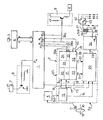
- the calculation system essentially comprises a first computer 1 constituted by a programmed microprocessor of the current type ("single chip") such as, for example, the microprocessor MC 6801, and a second computer 2 which will be described more in detail below.
- a first computer 1 constituted by a programmed microprocessor of the current type ("single chip") such as, for example, the microprocessor MC 6801, and a second computer 2 which will be described more in detail below.
- the microprocessor 1 receives from a sensor 3 the pressure information in the intake manifold converted to digital form by a digital-to-analog converter 4, and from the computer 2 a synchronization signal Sy from which it calculates the engine speed and which allows it to identify the passage of each cylinder at TDC .
- the microprocessor 1 stores in memory values of feed angle and injection duration addressable as a function of the speed and pressure parameters and calculates, under the control of the synchronization signal Sy, the injection duration for the control of one or more injectors 6 and an injection pump 7 via power circuits 8 and 9 respectively.
- the microprocessor transmits by its outputs Po, P 1 , P 2 and P 3 the calculated value of the angle of advance on ignition to the computer 2.
- the computer 2 has a first section 2a and a second section 2b.
- the first section 2a consists of a digital processing block 13 which receives as input, after shaping by the analog circuit 5, constituted for example by the circuit SN 96 532 from the company Texas Instruments, the signal picked up by a sensor position 11 detecting the passage of the teeth which is provided at its periphery with a target 10 fixed on the crankshaft 12 of the internal combustion engine and rotating in synchronism with it. From the output signal S d of the analog circuit 5, the block 13 produces the synchronization signal Sy and a speed signal V of frequency n times greater than Sd.
- This block 13 and the manner in which the signals Sy and nSd are produced are described in French patent 2,446,467 to which reference may be made.
- Section 2b includes a calculation block 19 which receives on an input 16 the synchronization signal Sy and on a second input 17 speed signal V.
- the essential parts of the calculation block 19 are the following: a sequencer 30; a speed measuring stage 31; a read only memory 32; a pressure measurement stage 33; a security stage 34 to guard against any operational incident of the computer block 19; a correction stage 35 connected by three conduc entry agents 38a, 38b; 38c at the outputs Po, P1 and P2 respectively of the microprocessor 1 and a stage 36 for calculating the ignition advance angle receiving information from the output P3 of the microprocessor 1 by an input 41 of serial pulses.
- This calculation block has been described in French patents 2,327,421, 2,349,041 and 2,414,127.
- the calculation block 19 delivers by its respective outputs 21 and 22 two binary numbers which correspond respectively to the angle of conduction of the coil 27 expressed in number of teeth of the target 10 on its output 21 and to the angle d 'ignition advance expressed in number of teeth of target 10 and in number of subdivisions between two teeth of said target on its output 22. These two binary numbers arrive via conductors 21 and 22 as input on a block 20 for generating the control signal from the coil 27.
- the block 20 also receives as input three signals by the conductors 14, 15 and 18 which are respectively the sensor signal shaped Sd, the speed signal V and the synchronization signal Sy .
- the generation block 20 of the coil control signal provides on its output 23 a low power signal which is transmitted to an amplifier power stage 24 whose output 28 is connected to the ignition coil 27 having a primary winding 26 and a secondary winding 29 connected by one of its ends to the central part of a distributor 42 around which rotates the movable arm 43 which successively puts in communication, during its rotation, the secondary 29 of the ignition coil 27 with the spark plugs of the different cylinders of the engine to cause the explosion and combustion of the mixture contained in the cylinders.
- This latter assembly comprising the block 20 for generating the control signal from the coil 27 and the power amplifier stage 24, was described in French patent application 2,474,597.
- the computer 2 which has just been described briefly and the detailed operation of which is explained in the aforementioned patents can be constituted by an integrated circuit such as the circuit SN 96 528 from the company Texas Instruments.
- This circuit is in principle intended to calculate autonomously the conduction angle of the coil 27 and the ignition advance angle.
- the device according to the invention fulfills only the first of these functions, the second being provided by the microprocessor 1.
- the additional inputs 38a, 38b, 38c normally used to receive additional and random corrections from various sensors and the input 41 for correction of advance according to the knock are, in the present device, intended to receive permanent corrections coming from the microprocessor 1 and serving to generate the ignition law.
- calculation block 19 does not receive "pressure” information, contrary to what is indicated in the French patent application 2,485,641 since it is the microprocessor 1 which receives this information directly from the analog / digital converter 4, which allows the use of a single pressure sensor 3 to calculate the ignition advance angle and the injection time.
- the target 10 comprises for example 44 regularly spaced teeth, twice of which two teeth have been removed 90 * from each top dead center or bottom dead center in the case of a four-cylinder engine.
- the signal Sd coming from the sensor 11 and shaped by the analog circuit 5 is applied to the computer 2.
- Block 13 operates the processing of this signal Sd (not to be confused with the signal Sd of the aforementioned French patent 2,446,467 which, it, designates the reconstituted tooth signal, i.e. the sensor signal shaped and in which the missing teeth have also been reconstituted electronically) so as to produce the signal Sy which identifies the passage of the pistons to a top dead center .
- the microprocessor which also receives this signal Sy can then calculate the engine speed and, from the pressure information coming from the converted sor 4, the ignition advance angle and the injection duration, in synchronism with the motor cycles, according to appropriate algorithms and which will not be described, such algorithms being well known to those skilled in the art.
- the microprocessor 1 controls the start of the injection at a given time after the top dead center and for the calculated duration.
- microprocessor 1 indicates to block 19 what angle of advance it must provide to block 19.
- microprocessor 1 can indicate all feeds between 0 ° and 56 ° flywheel in 8 ° steps. The maximum value of 56 ° is generally largely sufficient for all internal combustion engines.
- the output P3 of microprocessor 1 is used to refine the generation of the advance law and obtain a precision of 1 ° on the advance angle. To this end, the output P 3 of the microprocessor 1 is connected to the input 41 of the calculation block 19, including another input 40, which controls the sign of the correction applied to the input 41, is pre-positioned so that this sign is negative.
- the microprocessor 1 therefore has to send in parallel only information "0" or "1" on the three inputs 38a, 38b and 38c to roughen the advance value to be generated in steps of 8 °, which value is decremented from degree to degree by sending to input 41 a number of pulses between 0 and 7 to correct the "rough" value and indicate in block 19, with a resolution of 1 °, the value of advance to take into account.
- the calculation system of the control and ignition device according to the invention is therefore particularly inexpensive since it requires only one pressure sensor and that it associates with a microprocessor of common type and not very powerful a computer designed initially to independently generate the ignition law and mass production at low cost.
Landscapes
- Engineering & Computer Science (AREA)
- General Engineering & Computer Science (AREA)
- Computer Hardware Design (AREA)
- Chemical & Material Sciences (AREA)
- Combustion & Propulsion (AREA)
- Mechanical Engineering (AREA)
- Microelectronics & Electronic Packaging (AREA)
- Theoretical Computer Science (AREA)
- Signal Processing (AREA)
- Electrical Control Of Ignition Timing (AREA)
- Combined Controls Of Internal Combustion Engines (AREA)
- Ignition Installations For Internal Combustion Engines (AREA)
Applications Claiming Priority (2)
| Application Number | Priority Date | Filing Date | Title |
|---|---|---|---|
| FR8213996 | 1982-08-11 | ||
| FR8213996A FR2531749B1 (fr) | 1982-08-11 | 1982-08-11 | Dispositif de commande de l'allumage et de l'injection de combustible pour un moteur a combustion interne |
Publications (2)
| Publication Number | Publication Date |
|---|---|
| EP0102273A1 true EP0102273A1 (de) | 1984-03-07 |
| EP0102273B1 EP0102273B1 (de) | 1986-12-03 |
Family
ID=9276807
Family Applications (1)
| Application Number | Title | Priority Date | Filing Date |
|---|---|---|---|
| EP83401543A Expired EP0102273B1 (de) | 1982-08-11 | 1983-07-27 | Zünd- und Einspritzungssteueranlage für eine Brennkraftmaschine |
Country Status (5)
| Country | Link |
|---|---|
| US (1) | US4489689A (de) |
| EP (1) | EP0102273B1 (de) |
| DE (1) | DE3368094D1 (de) |
| ES (1) | ES524849A0 (de) |
| FR (1) | FR2531749B1 (de) |
Cited By (3)
| Publication number | Priority date | Publication date | Assignee | Title |
|---|---|---|---|---|
| EP0170064A1 (de) * | 1984-06-29 | 1986-02-05 | MARELLI AUTRONICA S.p.A. | Elektronisches Zündsystem mit statischem Verteiler für einen Vergasermotor |
| EP0494467A3 (en) * | 1991-01-05 | 1992-10-21 | Delco Electronics Corp | Electronic control module |
| US7257073B2 (en) | 2000-08-31 | 2007-08-14 | Matsushita Electric Industrial Co., Ltd. | Optical disc and physical address format |
Families Citing this family (10)
| Publication number | Priority date | Publication date | Assignee | Title |
|---|---|---|---|---|
| US4791569A (en) * | 1985-03-18 | 1988-12-13 | Honda Giken Kogyo Kabushiki Kaisha | Electronic control system for internal combustion engines |
| JPH0765556B2 (ja) * | 1985-04-10 | 1995-07-19 | 株式会社日立製作所 | 内燃機関の点火制御装置 |
| US4922874A (en) * | 1989-06-30 | 1990-05-08 | Ford Motor Company | Automobile electronic control modules communicating by pulse width modulated signals |
| US5233964A (en) * | 1991-10-10 | 1993-08-10 | Ford Motor Company | Universal control of a plurality of fuel injectors for an internal combustion engine |
| JPH05340295A (ja) * | 1992-06-09 | 1993-12-21 | Toyota Motor Corp | 多気筒内燃機関の制御装置 |
| US5913302A (en) * | 1997-09-19 | 1999-06-22 | Brunswick Corporation | Ignition coil dwell time control system |
| DE19947764A1 (de) * | 1999-10-02 | 2001-04-12 | Bosch Gmbh Robert | Verfahren und Vorrichtung zum Erkennen des Arbeitszustandes eines Zylinders einer 6-Zylinder- oder 12-Zylinder-Verbrennungsmaschine |
| JP4096728B2 (ja) * | 2002-12-20 | 2008-06-04 | 日産自動車株式会社 | エンジン制御装置 |
| US20050076893A1 (en) * | 2003-10-09 | 2005-04-14 | Jingfeng Guan | Electronic timing system of automobile engine |
| CN104005868B (zh) * | 2014-05-07 | 2016-11-23 | 潍柴动力股份有限公司 | 一种喷油提前角补偿方法及系统 |
Citations (2)
| Publication number | Priority date | Publication date | Assignee | Title |
|---|---|---|---|---|
| US4181884A (en) * | 1977-07-20 | 1980-01-01 | Nippondenso Co., Ltd. | Rotational position detection device using a reference mark and two sensors spaced integer times apart |
| EP0013846A1 (de) * | 1979-01-09 | 1980-08-06 | Regie Nationale Des Usines Renault | Verfahren und Vorrichtung zur Bestimmung der Winkellage eines rotierenden Teiles |
Family Cites Families (5)
| Publication number | Priority date | Publication date | Assignee | Title |
|---|---|---|---|---|
| GB1548039A (en) * | 1975-10-09 | 1979-07-04 | Renault | Electronic control of the ignition system of an internal combustion engine |
| FR2414127A1 (fr) * | 1978-01-09 | 1979-08-03 | Renault | Dispositif de securite associe a une commande de temps de conduction d'une bobine |
| DE2903639A1 (de) * | 1979-01-31 | 1980-08-14 | Bosch Gmbh Robert | Rechnersystem zur steuerung einer vorrichtung in abhaengigkeit von steuersignalen |
| JPS5948307B2 (ja) * | 1979-02-23 | 1984-11-26 | 日産自動車株式会社 | 内燃機関の点火時期制御装置 |
| FR2474597A1 (fr) * | 1980-01-29 | 1981-07-31 | Renault | Dispositif de commande de bobine d'allumage pour moteur a combustion interne equipe d'un calculateur d'avance electronique |
-
1982
- 1982-08-11 FR FR8213996A patent/FR2531749B1/fr not_active Expired
-
1983
- 1983-07-27 EP EP83401543A patent/EP0102273B1/de not_active Expired
- 1983-07-27 DE DE8383401543T patent/DE3368094D1/de not_active Expired
- 1983-08-08 US US06/521,409 patent/US4489689A/en not_active Expired - Lifetime
- 1983-08-10 ES ES524849A patent/ES524849A0/es active Granted
Patent Citations (2)
| Publication number | Priority date | Publication date | Assignee | Title |
|---|---|---|---|---|
| US4181884A (en) * | 1977-07-20 | 1980-01-01 | Nippondenso Co., Ltd. | Rotational position detection device using a reference mark and two sensors spaced integer times apart |
| EP0013846A1 (de) * | 1979-01-09 | 1980-08-06 | Regie Nationale Des Usines Renault | Verfahren und Vorrichtung zur Bestimmung der Winkellage eines rotierenden Teiles |
Non-Patent Citations (3)
| Title |
|---|
| AUTOMOTIVE ENGINEERING, vol. 89, no. 8, août 1981, pages 28-34, Society of Automotive Engineers, Inc., Dallas, Texas, US * |
| ELECTRONIC DESIGN, vol. 29, no. 10, mai 1981, pages 197-202, Waseca, MN., US * |
| PATENTS ABSTRACTS OF JAPAN, vol. 4, no. 164, 14 novembre 1980, page 49 M 41 & JP - A - 55 112 861 (NISSAN JIDOSHA K.K.) 01-09-1980 * |
Cited By (10)
| Publication number | Priority date | Publication date | Assignee | Title |
|---|---|---|---|---|
| EP0170064A1 (de) * | 1984-06-29 | 1986-02-05 | MARELLI AUTRONICA S.p.A. | Elektronisches Zündsystem mit statischem Verteiler für einen Vergasermotor |
| EP0494467A3 (en) * | 1991-01-05 | 1992-10-21 | Delco Electronics Corp | Electronic control module |
| US7257073B2 (en) | 2000-08-31 | 2007-08-14 | Matsushita Electric Industrial Co., Ltd. | Optical disc and physical address format |
| US7269117B2 (en) | 2000-08-31 | 2007-09-11 | Matsushita Electric Industrial Co., Ltd. | Optical disc and physical address format |
| US7269116B2 (en) | 2000-08-31 | 2007-09-11 | Matsushita Electric Industrial Co., Ltd. | Optical disc and physical address format |
| US7327660B2 (en) | 2000-08-31 | 2008-02-05 | Matsushita Electric Industrial Co., Ltd. | Optical disc and physical address format |
| US7593313B2 (en) | 2000-08-31 | 2009-09-22 | Panasonic Corporation | Optical disc and physical address format |
| US7593314B2 (en) | 2000-08-31 | 2009-09-22 | Panasonic Corporation | Optical disc and physical address format |
| US7596076B2 (en) | 2000-08-31 | 2009-09-29 | Panasonic Corporation | Optical disc and physical address format |
| US7848216B2 (en) | 2000-08-31 | 2010-12-07 | Panasonic Corporation | Optical disc and physical address format |
Also Published As
| Publication number | Publication date |
|---|---|
| DE3368094D1 (en) | 1987-01-15 |
| FR2531749A1 (fr) | 1984-02-17 |
| FR2531749B1 (fr) | 1987-03-20 |
| ES8404466A1 (es) | 1984-05-01 |
| ES524849A0 (es) | 1984-05-01 |
| US4489689A (en) | 1984-12-25 |
| EP0102273B1 (de) | 1986-12-03 |
Similar Documents
| Publication | Publication Date | Title |
|---|---|---|
| EP0102273B1 (de) | Zünd- und Einspritzungssteueranlage für eine Brennkraftmaschine | |
| EP0532419B1 (de) | Verfahren und Vorrichtung zur Drehmomentmessung von Wärmemotoren mit interner Verbrennung | |
| EP0987421B1 (de) | Verfahren zur Erkennung der Phase der Zylinder einer Mehrzylinder-Viertaktbrennkraftmaschine. | |
| FR2711185A1 (fr) | Système d'acquisition et de traitement instantané de données pour le contrôle d'un moteur à combustion interne. | |
| FR2756591A1 (fr) | Installation pour reguler un moteur a combustion interne | |
| FR2689934A1 (fr) | Procédé et dispositif de détection des irrégularités de combustion d'un moteur en particulier à moyen et haut régimes, application à un système de contrôle d'un moteur à injection. | |
| EP0532420B1 (de) | Verfahren und Vorrichtung zum Messen des Drehmomentes eines thermischen internen Verbrennungsmotors, insbesondere bei Berücksichtigung der Rückführung des Auspuffgases und des zurückbleibenden verbrannten Gases und des Verbrennungsmittelüberschusses | |
| FR2664652A1 (fr) | Systeme d'injection de carburant pour un moteur a combustion interne, notamment pour une pompe a carburant commandee par une vanne electromagnetique. | |
| FR2691207A1 (fr) | Système pour commander un dispositif de dosage de carburant contrôlé par vanne électromagnétique. | |
| EP0101342B1 (de) | Optimierungsverfahren des Zündzeitpunktes einer Brennkraftmaschine | |
| EP0029374B1 (de) | Signal-generator zur Korrektur der Einstellung der Frühzündung in Abhängigkeit vom Klopfverhalten | |
| US5622154A (en) | Fuel system | |
| FR2937684A1 (fr) | Procede de determination de la duree d'une dent longue d'une cible montee sur un vilebrequin de moteur a combustion interne | |
| FR2485641A1 (fr) | Procede et dispositif de commande electronique d'allumage pour moteur a combustion interne | |
| FR2523214A1 (fr) | Dispositif et procede de determination de la position du piston dans le cylindre d'un moteur a mouvement alternatif | |
| FR2734326A1 (fr) | Procede de detection des rates a l'allumage d'un moteur a combustion interne a plusieurs cylindres | |
| EP0695865B1 (de) | Verfahren zur Korrektur der Unsymmetrien eines Geberrades | |
| FR2778433A1 (fr) | Installation de regulation d'un moteur a combustion interne a plusieurs cylindres | |
| FR2757945A1 (fr) | Procede de calcul du couple d'un moteur thermique a injection commandee electroniquement | |
| EP0128817A1 (de) | Verfahren zur Regelung und Messung des Alterns einer Brennkraftmaschine | |
| EP0033280B1 (de) | Steuerungsvorrichtung für die Zündspule eines Verbrennungsmotors mit einem elektronischen Rechner zur Zündverstellung | |
| JPS59101559A (ja) | エンジンシステム | |
| FR2549154A1 (fr) | Procede et dispositif de commande du processus de combustion dans un moteur a combustion interne | |
| EP0932751A1 (de) | Synchronisationsverfahren für das elektronische regelsystem einer brennkraftmaschine | |
| FR2911919A1 (fr) | Procede de synchronisation d'un moteur a combustion interne |
Legal Events
| Date | Code | Title | Description |
|---|---|---|---|
| PUAI | Public reference made under article 153(3) epc to a published international application that has entered the european phase |
Free format text: ORIGINAL CODE: 0009012 |
|
| 17P | Request for examination filed |
Effective date: 19830730 |
|
| AK | Designated contracting states |
Designated state(s): BE DE GB IT NL SE |
|
| GRAA | (expected) grant |
Free format text: ORIGINAL CODE: 0009210 |
|
| AK | Designated contracting states |
Kind code of ref document: B1 Designated state(s): BE DE GB IT NL SE |
|
| ITF | It: translation for a ep patent filed | ||
| REF | Corresponds to: |
Ref document number: 3368094 Country of ref document: DE Date of ref document: 19870115 |
|
| PLBE | No opposition filed within time limit |
Free format text: ORIGINAL CODE: 0009261 |
|
| STAA | Information on the status of an ep patent application or granted ep patent |
Free format text: STATUS: NO OPPOSITION FILED WITHIN TIME LIMIT |
|
| 26N | No opposition filed | ||
| ITTA | It: last paid annual fee | ||
| EAL | Se: european patent in force in sweden |
Ref document number: 83401543.0 |
|
| PGFP | Annual fee paid to national office [announced via postgrant information from national office to epo] |
Ref country code: GB Payment date: 19990614 Year of fee payment: 17 |
|
| PGFP | Annual fee paid to national office [announced via postgrant information from national office to epo] |
Ref country code: SE Payment date: 19990622 Year of fee payment: 17 |
|
| PGFP | Annual fee paid to national office [announced via postgrant information from national office to epo] |
Ref country code: NL Payment date: 19990624 Year of fee payment: 17 |
|
| PGFP | Annual fee paid to national office [announced via postgrant information from national office to epo] |
Ref country code: DE Payment date: 19990626 Year of fee payment: 17 |
|
| PGFP | Annual fee paid to national office [announced via postgrant information from national office to epo] |
Ref country code: BE Payment date: 19990706 Year of fee payment: 17 |
|
| PG25 | Lapsed in a contracting state [announced via postgrant information from national office to epo] |
Ref country code: GB Free format text: LAPSE BECAUSE OF NON-PAYMENT OF DUE FEES Effective date: 20000727 |
|
| PG25 | Lapsed in a contracting state [announced via postgrant information from national office to epo] |
Ref country code: SE Free format text: LAPSE BECAUSE OF NON-PAYMENT OF DUE FEES Effective date: 20000728 |
|
| PG25 | Lapsed in a contracting state [announced via postgrant information from national office to epo] |
Ref country code: BE Free format text: LAPSE BECAUSE OF NON-PAYMENT OF DUE FEES Effective date: 20000731 |
|
| BERE | Be: lapsed |
Owner name: REGIE NATIONALE DES USINES RENAULT Effective date: 20000731 |
|
| PG25 | Lapsed in a contracting state [announced via postgrant information from national office to epo] |
Ref country code: NL Free format text: LAPSE BECAUSE OF NON-PAYMENT OF DUE FEES Effective date: 20010201 |
|
| EUG | Se: european patent has lapsed |
Ref document number: 83401543.0 |
|
| GBPC | Gb: european patent ceased through non-payment of renewal fee |
Effective date: 20000727 |
|
| NLV4 | Nl: lapsed or anulled due to non-payment of the annual fee |
Effective date: 20010201 |
|
| PG25 | Lapsed in a contracting state [announced via postgrant information from national office to epo] |
Ref country code: DE Free format text: LAPSE BECAUSE OF NON-PAYMENT OF DUE FEES Effective date: 20010501 |