EP0102429B1 - Outillage composé - Google Patents
Outillage composé Download PDFInfo
- Publication number
- EP0102429B1 EP0102429B1 EP19820304671 EP82304671A EP0102429B1 EP 0102429 B1 EP0102429 B1 EP 0102429B1 EP 19820304671 EP19820304671 EP 19820304671 EP 82304671 A EP82304671 A EP 82304671A EP 0102429 B1 EP0102429 B1 EP 0102429B1
- Authority
- EP
- European Patent Office
- Prior art keywords
- die
- punch
- holder
- unit
- plate
- Prior art date
- Legal status (The legal status is an assumption and is not a legal conclusion. Google has not performed a legal analysis and makes no representation as to the accuracy of the status listed.)
- Expired
Links
Images


Classifications
-
- B—PERFORMING OPERATIONS; TRANSPORTING
- B21—MECHANICAL METAL-WORKING WITHOUT ESSENTIALLY REMOVING MATERIAL; PUNCHING METAL
- B21D—WORKING OR PROCESSING OF SHEET METAL OR METAL TUBES, RODS OR PROFILES WITHOUT ESSENTIALLY REMOVING MATERIAL; PUNCHING METAL
- B21D28/00—Shaping by press-cutting; Perforating
- B21D28/02—Punching blanks or articles with or without obtaining scrap; Notching
- B21D28/14—Dies
Definitions
- This invention relates to dies for shearing during stamping, and more particularly, to compound die assemblies for performing blanking and piercing at the same press stroke.
- Such a die assembly is described in patent specification DE-A-2505667.
- a die holder of compound die assembly is provided with slug clearance holes in order to remove punched slugs, and the compound die assembly is mounted on the press so that the slug clearance holes are disposed over openings of a bolster and a bed of the press.
- punched slugs corresponding to holes at peripheral portions of the blank do not drop into the bolster opening so that the slugs cannot be removed.
- parallel blocks beneath the die holder to form a space between the die holder and the press bolster in which punched slugs would be accumulated.
- the central portion of the die holder would be unsupported, and therefore, there would be the disadvantage that the die holder would be bent by the pressing force during blanking. Such a disadvantage would be increased in blanking parts having many holes close together, complicated holes and/or lengthy slits.
- the thickness of the die element and the die holder must be increased, but this would result in an increase in thickness and weight of the die assembly. Accordingly the compound die assembly has been thought to be unsuitable for the production of large-sized blanks.
- Embodiments of compound die assemblies according to this invention may also be suitable for the production of large-sized parts having holes close together, complicated holes and/or lengthy slits, and punched slugs may be readily removed from the assembly.
- the punch unit need not necessarily be fixed to the press ram so that mounting the die assembly onto the press is simple and die-height adjustment is not required.
- the present invention provides in a compound die assembly including a punch unit having a punch holder, at least one punch element, a blanking die element, and a knockout plate; a die unit having a die holder, a blanking punch element corresponding to said blanking die element and having a die hole corresponding to said at least one punch element, and a stripper plate; and guide post means for maintaining operative vertical alignment of said punch unit and said die unit; the improvement which comprises providing said blanking die and punch elements respectively as outer and inner pieces formed from a single plate by wire-cut electro-discharge machining and fixed directly to said punch and die holders respectively and said knock-out and stripper plates respectively as inner and outer pieces formed from a single plate by wire-cut electro-discharge machining and elastically supported on said punch and die holders.
- each guide post means fixed to said punch holder with the lower end portion thereof extending through a hole formed in said die holder, together with mount means adapted to be removably mounted on a press bolster and having a flat top surface on which said die unit and punch unit are supported and a set of holes for receiving the lower ends of said guide post means, clamping means being provided for fixing said die holder on to said mount means, said die holder having a plurality of load-supporting elements fixed near edges of slug clearance holes therein to form a slug accumulating space between said die holder and said mount means which communicates with the space surrounding said die holder.
- springs may be contained in respective holes of the mount to thereby urge the guide posts upwardly together with the punch unit.
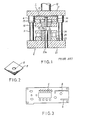
- the assembly shown includes a punch unit 1, a die unit 2, and a set of guide posts 3 for maintaining operative alignment of the punch unit and the die unit.
- Punch unit 1 is provided with a punch holder 11 which is formed with shank 12 for fixing the punch unit to a press ram (not shown).
- a backing plate 13 is secured onto the bottom surface of punch holder 11 by bolt means, and a punch plate 14 is also secured onto the bottom surface of backing plate 13 by bolt means.
- a piercing punch 15 is secured to punch plate 14 by being inserted into a hole of punch plate 14.
- Punch 15 is prevented from dropping down from punch plate 14 by engagement of its top collar with a shoulder of the hole of punch plate 14, and is also prevented from moving upwardly by engagement of its top surface with backing plate 13.
- a blanking die element 16 is supported from the bottom surface of punch plate 14 by bolt means with a spacer ring 17 therebetween.
- a knockout plate 18 is slidably fitted into the die hole of blanking die element 16, and punch 15 extends through knock- out plate 18.
- One or more elastic members 19 of, for example, polyurethane rubber are disposed between knockout plate 18 and punch plate 14 to urge knockout plate 18 downwardly. Knockout plate 18 is also prevented from dropping down by engagement of its top outer flange with the upper edge of the die hole of blanking die element 16.
- Die unit 2 is provided with a die holder 21 to be mounted on a press bolster (not shown), on which a die plate 22 is fixed.
- a blanking punch element 23 which corresponds to blanking die element 16 is fixed to die plate 22 and has a die hole 23a corresponding to punch 15.
- a stripper plate 24 is slidably fitted onto blanking pumch element 23 and is elastically supported on die plate 22 through one or more elastic members 25 of, for example, polyurethane rubber.
- Die holder 21 is provided with a slug clearance hole 21a corresponding to die hole 23a of blanking punch element 23.
- Guide posts 3 are fixed to die holder 21 and stand vertically thereon.
- Punch holder 11 is provided with guide bushings 4 receiving top end portions of guide posts 3, and operative vertical alignment of punch unit 1 and die unit 2 is maintained by fitting guide posts 3 into guide bushings 4.
- the compound die assembly is mounted on a press by fixing punch unit 1 to a press ram through shank 12 and by clamping die holder 21 onto a press bolster by clamping means (not shown).
- a blank is obtained which has an outer shape corresponding to the outer shape of blanking punch element 23 and a hole pierced by punch element 15.
- the blank obtained by use of the compound die assembly of Fig. 1 is shown in Fig. 2.
- 5 is the blank and 6 is a hole formed in the blank.
- the use of compound die assembly enables the performance of blanking and piercing simultaneously by one press stroke, and therefore enables the production of large numbers of blanks having holes without any variation in dimensions between the blanks. Accordingly, the compound die assembly can be employed for producing small-sized precision parts.
- the cost, volume and weight of the die assembly are necessarily increased.
- removal of slugs is difficult and the blanking punch element and the die holder are subject to bending, as described above. Therefore, the prior art compound die assembly is unsuitable for the production of large sized parts, in particular, such as parts having one or more slits, complicated openings and/or crowded holes as shown at a, b and c in Fig. 3.
- the present invention provides a compound die assembly which is suitable for the production of large-sized parts having many holes, complicated holes and/or slits.
- the blank 7 in Fig. 4 has a square hole 7a and two small circular holes 7b and 7c.
- the embodiment shown is similar to the known compound die assembly in that it has a punch unit 10, die unit 20 and guide posts 30, but the construction of those units is quite different from that in the known assembly.
- the illustrated embodiment is provided with a mount 40 and a plurality of load-supporting elements 50.
- Punch unit 10 includes a punch holder 101 and a blanking die element 103 which is directly fixed onto the bottom surface of punch holder 101 by bolt means 102.
- Blanking die element 103 has a die hole corresponding to the outer shape of the desired blank.
- Punch elements 104-106 are disposed in the die hole of blankingdie element 103.
- punch 104 is for forming square hole 7a of the blank of Fig. 4, and will be referred to as an inner blanking punch element.
- Punches 105 and 106 are for piercing holes 7b and 7c of the blank in Fig. 4.
- Inner blanking punch element 104 is fixed to punch holder 101 by bolt means 107 and pins 108.
- a knockout plate 109 which has an outer shape corresponding to the die hole of blanking die element 103 and holes corresponding to punches 104-105, is fitted in the die hole of blanking die element 103, and is supported from punch holder 101 by hanger bolts 110.
- One or more elastic members 111 of, for example, polyurethane rubber are disposed between knockout plate 109 and punch holder 101 so that knockout plate 109 can elastically sink into the die hole of blanking die element 103.
- Elastic members 111 are formed in a ring and are fixed to punch holder 101 by hanger bolts 110 and/or screws.
- the die unit is provided with a die holder 201 and a die element 203 which is directly fixed onto die holder 201 by bolt means 202.
- Die element 203 has an outer shape corresponding to the die hole of blanking die element 103 and serves as a blanking punch element.
- Die element 203 is also provided with die holes 203a and 203b corresponding to punches 104-106.
- a stripper plate 204 having a hole corresponding to the die hole of blanking die element 103 is fitted onto die element 203, and is supported on die holder 201 by hanger bolts 205.
- Elastic members 206 of, for example, polyurethane rubber are disposed between stripper plate 204 and die holder 201 so that stripper plate 204 can elastically sink below the top surface of die element 203.
- Die holder 201 is formed with slug clearance holes 201a a and 201b corresponding to die holes 203a and 203b.
- Guide posts 30 are fixed to punch holder 101 at their top end portions and extend downwardly through blanking die element 103. The lower end portions of guide posts 30 project downwardly from die holder 201 after extending through stripper plate 204 and die holder 201.
- Mount 40 for supporting punch unit 10 and die unit 20 is provided with a set of holes 401 for receiving the lower end portions of guide posts 30 in the flat surface.
- Coil springs 402 are contained within the holes 401. Therefore, upon being inserted into holes 401, the lower end portions of guide posts 30 are pushed up by springs 402, so that punch unit 10 is elastically supported in a condition raised from die unit 20.
- Die unit 20 is fixed onto mount 40 by fittings 403 and bolt means 404.
- a plurality of load-supporting elements 50 are fixed near the opening edges of slug clearance holes 201a a and 201 b on the bottom surface of die holder 201. Therefore, a space is formed between the bottom surface of die holder 201 and mount 40. the space communicates with the surrounding space of the die holder and serves for accumulation of slugs.
- load-supporting elements 50 are disposed not at the periphery of the die holder but near the slug clearance holes, bending of die element 203 and die holder 201 is advantageously prevented even if the holes to be pierced are slits, complicated, and/or crowded. Therefore, by utilising this arrangement of the compound die assembly, large-sized precision parts can be produced, and the die holder 201 and die element 203 can be relatively thin.
- blanking die and punch elements 103 and 203 are made from a sheet of plate by W.C.E.D.M. (Wire-cut electro-discharge machining).
- W.C.E.D.M. Wire-cut electro-discharge machining
- Fig. 11 it is known in the art to produce a die or a punch by the W.C.E.D.M. or by moving a wire 70 along an outer contour of a desired blank with the establishment of an electric spark between a work plate 60 and wire of, for example, phosphor bronze 70.
- wire 70 is inclined to form a tapered section, the separated inner and outer pieces 601 and 602 can be used as a punch and a die, respectively, so that punch and die sets can be produced by one cutting operation.
- the wire-inclination angle ⁇ must be selected depending on the thickness of the work plate 60 so as to make a suitable clearance I between tips of the punch 601 and die 602.
- Die 103 and punch 203 in the embodiment of Figs. 5-10 are made by this process.
- the resultant punch and die elements made according to this process fit more accurately together compared to those manufactured separately and the working time is reduced.
- one or more piercing die holes can also be formed in the resultant blanking punch element (601 in Fig. 11) by a similar W.C.E.D.M. process, and the separated pieces can be also used as punch elements.
- inner blanking punch element 104 is made by the process, but the other punch elements 105 and 106 are formed separately.
- Knockout plate 109 and stripper plate 204 in the embodiment of Figs. 5-8 are also made by a similar W.C.E.D.M. process without wire 70.
- mount 40 is disposed on a press bolster (not shown) and is firmly fixed thereto by any suitable clamping means.
- Die unit 20 is then fixed onto mount 40 by fittings and bolt means 403 and 404 after inserting coil springs 402 in holes 401 of mount 40.
- punch unit 10 is installed by inserting guide posts 30 into holes 401 of mount 40 thrugh guide-receiving holes of stripper plate 204 and die holder 201.
- the press ram moves downwardly to push down punch unit 10 against coil springs 402.
- a blank as shown in Fig. 4 is punched out.
- the punch unit 10 is raised by coil springs 402 to form a space between punch unit 10 and die unit 20 in which the work plate is disposed, so that punch unit 10 does not need to be fixed to the press ram. Therefore, installing the die assembly onto the press is quite simple, and no die-height adjustment is required.
- Punch elements 104 and 106 are prevented from upwardly slipping out of punch holder 101 by engagement of their top surfaces with the bottom surface of the press ram. However, if there are openings and/or depressions in the press ram surface, a flat plate may be disposed on the top surface of punch holder 101. Punch unit 10 may be fixed to the press ram if desired, and in that case coil springs 402 are not necessary.
- mount 40 may be provided with a plurality of guide-post-receiving holes 401 for each guide post, so that mount 40 can be used for different punch and die units.
- coil springs 402 are moved to new guide-post-receiving holes.
- mount 40 may be formed by three blocks 40a, 40b and 40c as shown in Fig. 9, with guide-post-receiving holes formed in two blocks 40a and 40b on opposite sides, with the central block 40c being replaceable by different blocks. In this arrangement, the mount can be used for supporting various punch and die units.
- 405 represents screw holes for receiving bolts 404 for fixing die unit 20.
- the blanking die element, punch elements, die or blanking punch element, knockout plate and stripper plate are made of alloy tool steel.
- the load-supporting elements need not be disks but could be blocks in the shapes of cubes, rectangles, for example.
- the load-supporting element is also made of alloy tool steel.
Landscapes
- Engineering & Computer Science (AREA)
- Mechanical Engineering (AREA)
- Punching Or Piercing (AREA)
- Mounting, Exchange, And Manufacturing Of Dies (AREA)
Claims (7)
Priority Applications (2)
| Application Number | Priority Date | Filing Date | Title |
|---|---|---|---|
| DE8282304671T DE3274957D1 (de) | 1982-09-06 | 1982-09-06 | Compound die assembly |
| EP19820304671 EP0102429B1 (fr) | 1982-09-06 | 1982-09-06 | Outillage composé |
Applications Claiming Priority (1)
| Application Number | Priority Date | Filing Date | Title |
|---|---|---|---|
| EP19820304671 EP0102429B1 (fr) | 1982-09-06 | 1982-09-06 | Outillage composé |
Publications (2)
| Publication Number | Publication Date |
|---|---|
| EP0102429A1 EP0102429A1 (fr) | 1984-03-14 |
| EP0102429B1 true EP0102429B1 (fr) | 1987-01-07 |
Family
ID=8189767
Family Applications (1)
| Application Number | Title | Priority Date | Filing Date |
|---|---|---|---|
| EP19820304671 Expired EP0102429B1 (fr) | 1982-09-06 | 1982-09-06 | Outillage composé |
Country Status (2)
| Country | Link |
|---|---|
| EP (1) | EP0102429B1 (fr) |
| DE (1) | DE3274957D1 (fr) |
Families Citing this family (40)
| Publication number | Priority date | Publication date | Assignee | Title |
|---|---|---|---|---|
| CN102259134B (zh) * | 2011-06-29 | 2012-12-19 | 无锡市中捷减震器有限公司 | 具有多种功能的一次成型模具 |
| CN102886425A (zh) * | 2012-09-17 | 2013-01-23 | 芜湖市续元工贸有限公司 | 钣金件冲孔模 |
| CN102941279A (zh) * | 2012-10-30 | 2013-02-27 | 芜湖可挺汽车底盘件有限公司 | 落料冲孔模具 |
| CN103170907A (zh) * | 2013-02-25 | 2013-06-26 | 大连国盛模具制造有限公司 | 一种便调式抛光模具 |
| CN103191973A (zh) * | 2013-03-26 | 2013-07-10 | 王丽琴 | 一种冲压模具 |
| CN103447387A (zh) * | 2013-08-16 | 2013-12-18 | 芜湖世达模具有限公司 | 一种落料冲孔模 |
| CN103506496A (zh) * | 2013-10-14 | 2014-01-15 | 湖北三众车桥有限责任公司 | 后桥壳三角板冲压模 |
| CN103691802B (zh) * | 2013-11-20 | 2016-02-03 | 无锡曙光模具有限公司 | 汽车发动机排气系统出气锥管外壳的切断模具 |
| CN103639265A (zh) * | 2013-11-26 | 2014-03-19 | 梧州恒声电子科技有限公司 | 一种导磁片落料模具的下模结构 |
| CN104785622A (zh) * | 2014-01-16 | 2015-07-22 | 无锡市高创精密机械有限公司 | 一种用于止推轴承的冲压模 |
| CN103920814A (zh) * | 2014-04-24 | 2014-07-16 | 靖江三鹏汽车模具制造有限公司 | 小零件的落料冲孔工艺 |
| CN103934356A (zh) * | 2014-05-13 | 2014-07-23 | 四川中邦模具有限公司 | 一种汽车前刹车盘的冲压模具 |
| CN103962440A (zh) * | 2014-05-19 | 2014-08-06 | 安徽大昌科技股份有限公司 | 一种膝部保护支架的复合模具 |
| CN104889254A (zh) * | 2015-06-18 | 2015-09-09 | 广西柳州市昌业机械制造有限公司 | 零件冲孔翻边模 |
| CN105013950A (zh) * | 2015-07-23 | 2015-11-04 | 广西柳拖车辆有限公司 | 电动汽车横梁加强板压形模 |
| CN105642734B (zh) * | 2016-01-07 | 2017-07-11 | 大连理工大学 | 一种凸凹模在线加工的微冲裁系统 |
| CN105642736A (zh) * | 2016-03-17 | 2016-06-08 | 无锡曙光模具有限公司 | 一种壳状工件的切开模具 |
| CN105710220A (zh) * | 2016-04-05 | 2016-06-29 | 芜湖海华金属材料有限公司 | 一种端盖冲压模具 |
| CN105903807B (zh) * | 2016-04-18 | 2018-02-06 | 旌德县皖星电子电器厂 | 一种导板式冲孔模 |
| CN106111796B (zh) * | 2016-07-29 | 2018-02-13 | 成都宏明双新科技股份有限公司 | 一种级进模内径向切边机构及切边方法 |
| CN106111800A (zh) * | 2016-08-31 | 2016-11-16 | 成都宏明双新科技股份有限公司 | 一种利用载体落料的屏蔽罩成型精密级进模 |
| CN106166583A (zh) * | 2016-08-31 | 2016-11-30 | 成都宏明双新科技股份有限公司 | 一种屏蔽罩复合成型精密级进模 |
| CN107199448A (zh) * | 2017-06-13 | 2017-09-26 | 新乡市振英机械设备有限公司 | 一种旋振筛防尘罩的压装设备 |
| CN107138621B (zh) * | 2017-07-06 | 2019-12-17 | 祥丰(浙江)金属制品有限公司 | 一种制备搪瓷花瓶坯体的切边翻边复合模 |
| CN109201889A (zh) * | 2018-10-10 | 2019-01-15 | 哈尔滨建成集团有限公司 | 一种双壁交叉弯曲异形弹簧冲孔落料复合模具 |
| CN109676035B (zh) * | 2019-02-21 | 2024-02-09 | 浙江鑫淼汽车部件有限公司 | 一种无废料在线冲压模具 |
| CN110014477A (zh) * | 2019-04-12 | 2019-07-16 | 江苏神通阀门股份有限公司 | 一种橡胶膜片冲剪模具 |
| CN110280646B (zh) * | 2019-07-23 | 2023-12-22 | 西安工业大学 | 冷冲压模具 |
| CN110369614B (zh) * | 2019-07-24 | 2021-06-08 | 深圳数码模汽车技术有限公司 | 一种具有模内快速调节及拆换模芯组件的冲压模具 |
| CN110961521B (zh) * | 2019-12-30 | 2025-08-08 | 安徽龙磁精密器件有限公司 | 一种用于换向器生产的冲贴片模具 |
| CN111231000B (zh) * | 2020-01-14 | 2021-04-30 | 厦门誉信实业有限公司 | 一种电子元器件冲切装置 |
| CN111230025B (zh) * | 2020-03-11 | 2021-06-15 | 张巧 | 一种大型跑道形轴件锻造模具 |
| CN113198905A (zh) * | 2021-05-06 | 2021-08-03 | 北京天立成信机械电子设备有限公司 | 一种门扇铰耳加强板的冲模设备及冲压工艺 |
| CN113210493A (zh) * | 2021-06-04 | 2021-08-06 | 安徽宏源铁塔有限公司 | 一种垫片加工一次成型模具 |
| CN113199263B (zh) * | 2021-06-15 | 2024-07-16 | 浙江亿利达科技有限公司 | 一种框架底槽铁柔性节能加工线 |
| CN113681644B (zh) * | 2021-08-25 | 2022-10-18 | 贵州振华华联电子有限公司 | 一种橡胶零件复合冲裁装置 |
| WO2023122870A1 (fr) * | 2021-12-27 | 2023-07-06 | 无锡微研股份有限公司 | Structure de chute de matériau |
| CN114589250B (zh) * | 2022-03-02 | 2023-07-14 | 广州市晟阳金属制品有限公司 | 一种翻边连接件的冲模工艺及其模具 |
| CN116652029B (zh) * | 2023-07-25 | 2023-09-26 | 烟台安信机电科技有限公司 | 一种连续冲压模具 |
| CN117282887B (zh) * | 2023-09-28 | 2026-04-03 | 浙江长瑞精密零部件制造有限公司 | 一种圆头内六角方颈螺栓加工装置及其使用方法 |
Family Cites Families (7)
| Publication number | Priority date | Publication date | Assignee | Title |
|---|---|---|---|---|
| US1543010A (en) * | 1925-06-23 | X x x x x p punch | ||
| US3125917A (en) * | 1964-03-24 | Punch and die assembly having spaced tool positioning plates | ||
| CH325224A (fr) * | 1952-12-03 | 1957-10-31 | Patrignani Leonida | Installation permettant d'assurer un cycle complet de travail sur des machines industrielles, notamment des presses, marteaux-pilons, moutons, machines à estamper |
| DE2144085A1 (de) * | 1971-09-02 | 1973-03-08 | Siemens Ag | Verfahren zur herstellung von teilen fuer schnittwerkzeuge, wie matrizen, stempel oder auch andere formkoerper mit hintersetzten flaechen, aus einem vorzugsweise planparallele flaechen aufweisenden werkstueck durch elektrothermisches drahterodieren sowie drahterodiermaschine zur durchfuehrung des verfahrens |
| CH564386A5 (en) * | 1973-03-08 | 1975-07-31 | Styner & Bienz Ag | Press tool stripper plate and ejection pad - is made from polyurethane foam to reduce overall tool height and setting up time |
| US3849624A (en) * | 1973-05-29 | 1974-11-19 | Andrew Eng Co | Wire electrode electric erosion device |
| DE2505667A1 (de) * | 1975-02-11 | 1976-08-19 | Pkm Planungsgesellschaft Fuer | Werkzeug zum stanzen und/oder praegen |
-
1982
- 1982-09-06 DE DE8282304671T patent/DE3274957D1/de not_active Expired
- 1982-09-06 EP EP19820304671 patent/EP0102429B1/fr not_active Expired
Also Published As
| Publication number | Publication date |
|---|---|
| DE3274957D1 (de) | 1987-02-12 |
| EP0102429A1 (fr) | 1984-03-14 |
Similar Documents
| Publication | Publication Date | Title |
|---|---|---|
| EP0102429A1 (fr) | Outillage composé | |
| US4501179A (en) | Compound die assembly | |
| US3296905A (en) | Compressive stripping unit and indexing type nibbling punch for turret punch presses and the like | |
| US3580122A (en) | Apparatus for making knockouts in electrical boxes formed of plastic material | |
| EP0437978B1 (fr) | Machine à estamper et a mouler ayant des pièces à estamper interchangeables auxilaires d'assemblage | |
| EP0376240A1 (fr) | Presse à étirer | |
| CN212190829U (zh) | 一种法兰冲孔模具 | |
| JPH0910860A (ja) | プレス打抜装置 | |
| JPH10156597A (ja) | 可変式プレス金型構造 | |
| US2378603A (en) | Punching apparatus | |
| JPH0344346Y2 (fr) | ||
| CN212442841U (zh) | 铝合金冲压翻边复合模具 | |
| CN113118298B (zh) | 一种机动车号牌专用固封装置零件的加工工艺和冲压模具 | |
| US3735653A (en) | Method for making knock-outs in electrical boxes formed of plastic material | |
| CN213826723U (zh) | 一种用于生产电机铁芯冲压床的固定装置 | |
| SU1074626A1 (ru) | Штамп дл вырубки | |
| RU2436648C2 (ru) | Универсальный комбинированный штамп для вырубки заготовки и вытяжки изделий | |
| CN2062659U (zh) | 微孔冲制模具 | |
| CN217701092U (zh) | 一种两片罐空罐生产专用冲压机用快装式模头 | |
| CN217700953U (zh) | 一种冲孔位置可调的上模结构及模具 | |
| CN218903274U (zh) | 一种圆柱电池壳落料杯体的一出多穴模具 | |
| SU1375381A1 (ru) | Штамп совмещенного действи | |
| CN218946094U (zh) | 一种适用于多折弯板的冲孔模具 | |
| CN223476106U (zh) | 车用abs挡盖连续式冲压模具 | |
| CN217964330U (zh) | 一种上梁管冲压机 |
Legal Events
| Date | Code | Title | Description |
|---|---|---|---|
| PUAI | Public reference made under article 153(3) epc to a published international application that has entered the european phase |
Free format text: ORIGINAL CODE: 0009012 |
|
| AK | Designated contracting states |
Designated state(s): BE DE GB IT |
|
| 17P | Request for examination filed |
Effective date: 19840518 |
|
| GRAA | (expected) grant |
Free format text: ORIGINAL CODE: 0009210 |
|
| AK | Designated contracting states |
Kind code of ref document: B1 Designated state(s): BE DE GB IT |
|
| REF | Corresponds to: |
Ref document number: 3274957 Country of ref document: DE Date of ref document: 19870212 |
|
| ITF | It: translation for a ep patent filed | ||
| PLBE | No opposition filed within time limit |
Free format text: ORIGINAL CODE: 0009261 |
|
| STAA | Information on the status of an ep patent application or granted ep patent |
Free format text: STATUS: NO OPPOSITION FILED WITHIN TIME LIMIT |
|
| 26N | No opposition filed | ||
| PGFP | Annual fee paid to national office [announced via postgrant information from national office to epo] |
Ref country code: BE Payment date: 19900912 Year of fee payment: 9 |
|
| ITTA | It: last paid annual fee | ||
| PGFP | Annual fee paid to national office [announced via postgrant information from national office to epo] |
Ref country code: DE Payment date: 19901129 Year of fee payment: 9 |
|
| PG25 | Lapsed in a contracting state [announced via postgrant information from national office to epo] |
Ref country code: BE Effective date: 19910930 |
|
| BERE | Be: lapsed |
Owner name: IWATA TETSUTARO Effective date: 19910930 |
|
| PG25 | Lapsed in a contracting state [announced via postgrant information from national office to epo] |
Ref country code: DE Effective date: 19920602 |
|
| PGFP | Annual fee paid to national office [announced via postgrant information from national office to epo] |
Ref country code: GB Payment date: 19920907 Year of fee payment: 11 |
|
| PG25 | Lapsed in a contracting state [announced via postgrant information from national office to epo] |
Ref country code: GB Effective date: 19930906 |
|
| GBPC | Gb: european patent ceased through non-payment of renewal fee |
Effective date: 19930906 |