EP0102465A1 - Haltevorrichtung für die Isolation eines elektrischen Widerstandsofens sowie für dessen Heizelemente - Google Patents
Haltevorrichtung für die Isolation eines elektrischen Widerstandsofens sowie für dessen Heizelemente Download PDFInfo
- Publication number
- EP0102465A1 EP0102465A1 EP83105996A EP83105996A EP0102465A1 EP 0102465 A1 EP0102465 A1 EP 0102465A1 EP 83105996 A EP83105996 A EP 83105996A EP 83105996 A EP83105996 A EP 83105996A EP 0102465 A1 EP0102465 A1 EP 0102465A1
- Authority
- EP
- European Patent Office
- Prior art keywords
- holding device
- furnace
- extension
- heating elements
- wall
- Prior art date
- Legal status (The legal status is an assumption and is not a legal conclusion. Google has not performed a legal analysis and makes no representation as to the accuracy of the status listed.)
- Granted
Links
- 238000010438 heat treatment Methods 0.000 title claims abstract description 27
- 238000004873 anchoring Methods 0.000 title 1
- 239000000463 material Substances 0.000 claims abstract description 8
- 239000000919 ceramic Substances 0.000 claims abstract description 7
- 238000009413 insulation Methods 0.000 claims description 8
- 239000002657 fibrous material Substances 0.000 claims description 5
- 239000012212 insulator Substances 0.000 abstract 4
- 239000000835 fiber Substances 0.000 abstract 2
- 238000004519 manufacturing process Methods 0.000 description 3
- 239000007787 solid Substances 0.000 description 3
- 239000011810 insulating material Substances 0.000 description 1
- 239000002184 metal Substances 0.000 description 1
Images


Classifications
-
- H—ELECTRICITY
- H05—ELECTRIC TECHNIQUES NOT OTHERWISE PROVIDED FOR
- H05B—ELECTRIC HEATING; ELECTRIC LIGHT SOURCES NOT OTHERWISE PROVIDED FOR; CIRCUIT ARRANGEMENTS FOR ELECTRIC LIGHT SOURCES, IN GENERAL
- H05B3/00—Ohmic-resistance heating
- H05B3/62—Heating elements specially adapted for furnaces
- H05B3/66—Supports or mountings for heaters on or in the wall or roof
-
- F—MECHANICAL ENGINEERING; LIGHTING; HEATING; WEAPONS; BLASTING
- F27—FURNACES; KILNS; OVENS; RETORTS
- F27D—DETAILS OR ACCESSORIES OF FURNACES, KILNS, OVENS OR RETORTS, IN SO FAR AS THEY ARE OF KINDS OCCURRING IN MORE THAN ONE KIND OF FURNACE
- F27D1/00—Casings; Linings; Walls; Roofs
- F27D1/0003—Linings or walls
- F27D1/0006—Linings or walls formed from bricks or layers with a particular composition or specific characteristics
- F27D1/0009—Comprising ceramic fibre elements
-
- F—MECHANICAL ENGINEERING; LIGHTING; HEATING; WEAPONS; BLASTING
- F27—FURNACES; KILNS; OVENS; RETORTS
- F27D—DETAILS OR ACCESSORIES OF FURNACES, KILNS, OVENS OR RETORTS, IN SO FAR AS THEY ARE OF KINDS OCCURRING IN MORE THAN ONE KIND OF FURNACE
- F27D1/00—Casings; Linings; Walls; Roofs
- F27D1/0003—Linings or walls
- F27D1/0036—Linings or walls comprising means for supporting electric resistances in the furnace
-
- F—MECHANICAL ENGINEERING; LIGHTING; HEATING; WEAPONS; BLASTING
- F27—FURNACES; KILNS; OVENS; RETORTS
- F27D—DETAILS OR ACCESSORIES OF FURNACES, KILNS, OVENS OR RETORTS, IN SO FAR AS THEY ARE OF KINDS OCCURRING IN MORE THAN ONE KIND OF FURNACE
- F27D1/00—Casings; Linings; Walls; Roofs
- F27D1/14—Supports for linings
- F27D1/144—Supports for ceramic fibre materials
Definitions
- the invention relates to a holding device made of high temperature resistant material for an insulation made of mats or molded parts of an electrical resistance furnace made of ceramic fiber material, which is attached with its outside to structural elements of the furnace and with its inside to flanges of the holding device, the holding device consisting of a cup-like body a floor, a wall, which is attached to the wall and facing outward flange and an extension facing the inside of the furnace, on which a holder for electrical resistance heating elements of the furnace is formed at a distance from the inner surface of the insulation, and wherein on the bottom of the holding device a means for releasably attaching the holding device to one of the structural elements of the furnace.
- the holding device there consists of two of these cup-like bodies, the walls of which taper to a small extent and which are spaced apart from one another.
- the annular space formed between the two flanges of both cup-like bodies serves to hold the electrical heating elements of the furnace with the advantage that the heating elements, which are very hot during operation, are kept at a distance from the inner surface of the insulation.
- the heating elements can therefore be heated to a noticeably higher degree without the service life of the fiber material of the insulation suffering.
- a disadvantage of this is that the known holding device described only on the side walls of the furnace can be used. This is because the heating elements cannot be held on the holding device on the furnace ceiling because they can only be placed on the cylindrical body between the two flanges of the holding device from above.
- the invention is therefore based on the object of developing a holding device of the type mentioned in such a way that the holding device can also be used on the ceiling of an electrical resistance furnace while maintaining its advantages.
- the invention is characterized in that at least one passage opening serving as a holder for support tubes for the electrical resistance heating elements is formed in the extension of the holding device.
- the heating elements are thus helically wound on support tubes in a known manner and the assembly consisting of the support tubes with the wound heating elements can now be inserted into the passage opening which is formed on the extension of the holding device.
- the support tube with its heating element is thus held on all sides in the passage opening, so that the holding device according to the invention can be used not only advantageously on the side walls but also on the ceiling of such an oven, without any design changes.
- the advantage remains that the actual heating element is held at a distance from the inner surface of the insulation made of the ceramic fiber material and the mats or molded parts forming the insulation are held with their inside on the flange of the holding device.
- the extension can be hollow or solid. The same applies to the actual body of the holding device. If the extension is hollow, the support tubes with the heating elements can also be placed on the notches from above, which are formed by the openings in the wall of the hollow extension, provided that the holding device is in the side wall of the furnace is used.
- a hollow extension also requires less material, combined with a low heat capacity and low heat conduction. In some applications, however, it is advantageous if the extension - possibly including its body - is massive, because the holding device can then be subjected to higher mechanical loads.
- extension is formed in one piece with the body, namely from high-temperature-resistant material, preferably from ceramic or metal.
- the two parts can therefore not separate from each other even after a long period of operation, as is possible with the prior art described.
- the extension is made separately from the actual body.
- the extension has an inwardly facing flange at one end, which engages under the outwardly facing flange of the body. As a result, both parts are permanently connected.
- the support tubes mentioned for the electrical heating elements are usually profiled in a circular shape. It follows therefore a particularly good hold of the support tube together with its heating coil if the passage opening has a circular cross section. If necessary, however, different cross sections can also be provided, for example oval or prism-shaped cross sections.
- this can have a continuous transverse bore to form the passage opening.
- This holding device consists of a body 1 which, in the exemplary embodiments shown, tapers conically towards the outside of the furnace. Its outer surface is circular. Basically, the body is pot-shaped, ie it has a wall 2 and a bottom 3. At the free edge of the wall 2 ; an all-round flange 4 is formed. The bottom 3 has a circular or elongated hole 5 for the passage of a fastening means 6.
- This fastening means is a fastening pin or a fastening bolt. Its outer end with respect to the furnace is suitably connected to the stable structure of the furnace wall 7 (see also FIGS. 3 and 4). A fastening disk or fastening nut 8 is pushed onto the fastening means 6 and secures it at an adjustable distance on the bottom 3 of the body 1.
- the flange 4 of the holding device lies either directly or via a washer 9 on the inner surface 10 of an insulating body 11 made of ceramic fiber material and thereby holds it against the furnace wall.
- the body 1 thus penetrates into a corresponding recess in the insulating body 11.
- a plug 12 made of insulating material can be inserted into the body 1 in order to thermally protect the holding means 6, 8.
- An extension 13 is formed on the body 1 and has means for fastening support tubes 14 for electrical heating elements. These heating elements are shown in FIGS. 5 and 6 as heating coils 15. They are also possible in the other embodiments, but not shown in the drawing.
- the holding means for the support tubes 14 in the embodiments shown consist of contact surfaces 16 and a passage opening 17. These contact surfaces and passage openings are created in the cylindrical extension 13 in that punched-outs are made in two opposite locations in the wall of the extension, in which is then used one of the support tubes 14 together with the heating coil 15 (see Fig. 2). Alternatively, the support tube is placed on the respective upper contact surface 16. as shown in Fig. 1.
- the cutouts are, for example, circular, oval or prismatic.
- FIG. 3 shows the situation of FIG. 1 on a smaller scale, the connection of the fastening means 6 on the furnace wall 7 being additionally shown.
- Fig. 4 corresponds essentially to Fig. 3, but with the support tube 14 is inserted with its heating coil in the passage opening.
- the extension 13 has an all-round groove, which acts like the bearing surface 16.
- the extension has a continuous transverse bore similar to the passage opening 17 for fastening the support tubes to the ceiling.
- the body 1, 13 can also be held in the insulating body 11 in that its bottom 3 rests on a support element, for example a grid, embedded in the insulating body 11.
- the holding pin 6 is then omitted.
- the bearing surface 16 can also be profiled in a V-shape, for example.
- FIGS. 1 to 6 The one-piece design of body 1 and extension 13 shown in FIGS. 1 to 6 is characterized by good durability. However, two-part or multi-part production can also be recommended for manufacturing reasons. 7 shows an exemplary embodiment, wherein the extension 13 has an inner flange 18 which engages under the flange 4 of the body 1. Other connections between these components 1, 13 are also possible.
Landscapes
- Engineering & Computer Science (AREA)
- Mechanical Engineering (AREA)
- General Engineering & Computer Science (AREA)
- Chemical & Material Sciences (AREA)
- Ceramic Engineering (AREA)
- Furnace Details (AREA)
- Resistance Heating (AREA)
- Control Of Resistance Heating (AREA)
Abstract
Description
- Die Erfindung betrifft eine Haltevorrichtung aus hochtemperaturbeständigem Material für eine aus Matten oder Formteilen bestehende Isolation eines elektrischen Widerstandsofens aus keramischen Fasermaterial, die mit ihrer Außenseite an Strukturelementen des Ofens und mit ihrer Innenseite an Flanschen der Haltevorrichtung befestigt ist, wobei die Haltevorrichtung aus einem becherartigem Körper mit einem Boden, einer Wand, dem an der Wand angesetzten und nach außen weisenden Flansch und einer zum Ofeninneren weisenden Verlängerung-besteht, an der unter Abstand von der Innenfläche der Isolation eine Halterung für elektrische Widerstandsheizelemente des Ofens ausgebildet ist, und wobei am Boden der Haltevorrichtung ein Mittel zur lösbaren Befestigung der Haltevorrichtung an einem der Strukturelemente des Ofens angreift.
- Eine derartige Haltevorrichtung beschreibt die deutsche Offenlegungsschrift 28 01 587. Die Haltevorrichtung besteht dort aus zwei dieser becherartigen Körper, deren Wände sich in geringem Maße konisch verjüngen und die beabstandet voneinander ineinander gesetzt sind. Der zwischen den beidenFlanschen beider becherartiger Körper ausgebildete Ringraum dient zum Halten der elektrischen Heizelemente des Ofens mit dem Vorteil, daß die im Betrieb sehr heißen Heizelemente von der Innenfläche der Isolierung beabstandet gehalten werden. Verglichen mit dem sonst bekannten Stand der Technik können daher die Heizelemente fühlbar höher erhitzt werden, ohne daß darunter die Lebensdauer des Fasermaterials der Isolation leidet.
- Nachteilig hieran ist es aber, daß die beschriebene, bekannte Haltevorrichtung nur an den Seitenwänden des Ofens eingesetzt werden kann. An der Ofendecke finden nämlich die Heizelemente an der Haltevorrichtung keinen Halt, weil sie nur auf dem zylindrischen Körper zwischen den beiden Flanschen der Haltevorrichtung von oben aufgelegt werden können.
- Der Erfindung liegt daher die Aufgabe zugrunde, eine Haltevorrichtung der eingangs genannten Art dahingehend weiterzubilden, daß die Haltevorrichtung bei Beibehaltung ihrer Vorteile auch an der Decke eines elektrischen Widerstandsofens eingesetzt werden kann.
- Zur Lösung dieser-Aufgabe ist die Erfindung dadurch gekennzeichnet, daß in der Verlängerung der Haltevorrichtung wenigstens eine als Halterung für Tragrohre der elektrische Widerstandsheizelemente dienende Durchtrittsöffnung ausgebildet ist.
- Die Heizelemente werden somit auf Tragrohre in bekannter Weise wendelförmig aufgewickelt und die Baueinheit bestehend aus den Tragrohren mit den aufgewickelten Heizelementen kann jetzt in die Durchtrittsöffnung eingeschoben werden, die an der Verlängerung der Haltevorrichtung ausgebildet ist. Das Tragrohr mit seinem Heizelement wird somit allseitig in-der Durchtrittsöffnung gehalten, so daß die erfindungsgemäße Haltevorrichtung nicht nur vorteilhaft an den Seitenwänden, sondern auch an der Decke eines derartigen Ofens eingesetzt werden kann, und zwar ohne irgendwelche konstruktiven Änderungen. Dabei bleibt der Vorteil erhalten, daß das eigentliche Heizelement von der Innenfläche der Isolation aus dem keramischen Fasermaterial beabstandet gehalten wird und die die Isolation ausbildenden Matten oder Formteile werden mit ihrer Innenseite am Flansch der Haltevorrichtung gehalten.
- Die Verlängerung kann hohl oder auch massiv sein. Dasselbe gilt für den eigentlichen Körper der Haltevorrichtung Ist die Verlängerung hohl, so lassen sich die Tragrohre mit den Heizelementen auch auf die Einkerbungen von oben aufsetzen, die durch die Durchbrüche in der Wand der hohlen Verlängerung ausgebildet werden, sofern die Haltevorrichtung in der Seitenwand des Ofens eingesetzt wird. Eine hohle Verlängerung benötigt auch weniger Material, verbunden mit einer geringen Wärmekapazität und geringen Wärmeleitung. Bei einigen Anwendungen ist es aber vorteilhaft, wenn die Verlängerung - ggfs. mitsamt ihres Körpers - massiv ist, weil die Haltevorrichtung dann mechanisch höher belastbar ist.
- Bevorzugt wird es fernerhin, wenn die Verlängerung mit dem Körper einstückig ausgebildet ist, und zwar aus hochtemperaturbeständigem Material, vorzugsweise aus Keramik oder Metall. Die beiden Teile können sich somit auch nach längerer Betriebsdauer nicht voneinander lösen, wie dies beim geschilderten Stand der Technik möglich ist.
- Für eine leichtere Herstellung der Durchbrüche in der Verlängerung kann es aber auch vorteilhaft sein, wenn die Verlängerung getrennte vom eigentlichen Körper hergestellt wird. In diesem Fall wird es für eine gute Verbindung zwischen den beiden Bauteilen bevorzugt, wenn die Verlängerung an einem ihrer Enden einen nach innen weisenden Flansch hat, der unter den nach außen weisenden Flansch des Körpers greift. Dadurch werden beide Teile unlösbar miteinander verbunden.
- Die erwähnten Tragrohre für die elektrischen Heizelemente sind üblicherweise kreisrund profiliert. Es ergibt sich daher ein besonders guter Halt der Tragrohr mitsamt ihrer Heizwendel, wenn die Durchtrittsöffnung einen kreisrunden Querschnitt hat. Gegebenenfalls können aber auch abweichende Querschnitte vorgesehen sein, beispielsweise ovale oder prismenförmige Querschnitte.
- Bei massiv ausgebildeter Verlängerung kann diese zur Ausbildung der Durchtrittsöffnung eine durchgehende Querbohrung haben.
- Die Erfindung wird im folgenden anhand von Ausführungsbeispielen näher erläutert, aus denen sich weitere wichtige Merkmale ergeben. Es zeigt:
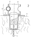
- Fig. 1 - einen Längsschnitt durch eine Haltevorrichtung nach der Erfindung bei Befestigung der Haltevorrichtung an einer Seitenwand eines Ofens;
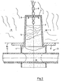
- Fig. 2 - eine Schnittansicht ähnlich Fig. 1 bei einer Befestigung der neuartigen Haltevorrichtung an der Decke eines Ofens;
- Fig. 3 - eine Darstellung ähnlich Fig. 1 in verkleinertem Maßstab zur Erläuterung des Prinzips mit einem auf eine Auflagefläche aufgelegten Tragrohr;
- Fig. 4 - eine Schnittansicht ähnlich Fig. 3 mit einem in eine Durchtrittsöffnung eingelegten Tragrohr;
- Fig. 5 - in vergrößertem Maßstab eine Ansicht in Richtung des Pfeiles A von Fig. 4;
- Fig. 6 - ebenfalls in vergrößertem Maßstab eine Ansicht in Richtung des Pfeiles B von Fig. 3;
- Fig. 7 - eine Darstellung ähnlich Fig. 1, bei der die Verlängerung am Körper befestigt ist.
- Zunächst soll anhand der Fig. 1 und 2 der grundsätzliche Aufbau der neuartigen Haltervorrichtung erläutert werden. Diese Haltevorrichtung besteht aus einem Körper 1, der bei den gezeigten Ausführungsbeispielen sich zur Außenseite des Ofens hin konisch verjüngt. Seine Mantelfläche ist kreisförmig. Grundsätzlich ist der Körper topfartig ausgebildet, d.h. er hat eine Wand 2 und einen Boden 3. An den freien Rand der Wand 2 ist ; ein ringsum laufender Flansch 4 angeformt. Der Boden 3 hat ein kreisrundes oder längliches Loch 5 für den Durchtritt eines Befestigungsmittels 6. Diese Befestigungsmittel ist ein Befestigungsstift oder ein Befestigungsbolzen. Sein bezüglich des Ofens äußeres Ende ist in geeigneter Weise mit der stabilen Struktur der Ofenwand 7 (vergleiche auch Fig. 3 und 4) verbunden. Eine Befestigungsscheibe oder Befestigungsmutter 8 ist auf das Befestigungsmittel 6 aufgeschoben und sichert dieses in einstellbarem Abstand am Boden 3 des Körpers 1.
- Der Flansch 4 der Haltevorrichtung liegt entweder direkt oder über eine Unterlegscheibe 9 an der Innenfläche 10 eines Isolierkörpers 11 aus keramischem Fasermaterial an und hält dieses dadurch an der Ofenwand. Der Körper 1 dringt also in eine entsprechende Vertiefung des Isolierkörpers 11 ein.
- Ein Stopfen 12 aus Isoliermaterial kann in den Körper 1 eingesetzt werden, um die Haltemittel 6, 8 thermisch zu schützen.
- An den Körper 1 ist eine Verlängerung 13 angeformt, die Mittel zur Befestigung von Tragrohren 14 für elektrische Heizelemente hat. Diese Heizelemente sind in Fig. 5 und 6 als Heizwendeln 15 eingezeichnet. Sie sind auch bei den anderen Ausführungsformen möglich, zeichnerisch aber nicht dargestellt.
- Die Haltemittel für die Tragrohre 14 bestehen bei den gezeigten Ausführungsformen aus Auflageflächen 16 und-einer Durchtrittsöffnung 17. Diese Auflageflächen und Durchtrittsöffnungen werden dadurch in der zylindrischen Verlängerung 13 angelegt, daß an zwei einander gegenüberliegenden Stellen in der Wand der Verlängerung 13 Ausstanzungen vorgenommen werden, in die dann eines der Tragrohre 14 mitsamt Heizwendel 15 eingesetzt wird (vgl. Fig.2). Alternativ wird das Tragrohr auf die jeweils obere Auflagefläche 16 aufgelegt. wie dies Fig. 1 zeigt. Die Ausstanzungen sind beispielsweise kreisförmig, oval oder prismenförmig. Fig. 3 zeigt in verkleinertem Maßstab die Situation von Fig. 1, wobei zusätzlich die Verbindung des Befestigungsmittels 6 an der Ofenwand 7 dargestellt ist.
- Fig. 4 entspricht im wesentlichen Fig. 3, wobei aber das Tragrohr 14 mit seiner Heizwendel in die Durchtrittsöffnung eingeschoben ist.
- Die Fig. 5 und 6 zeigen in vergrößertem Maßstab Ansichten der Halterung der Tragrohre mit Heizwendel bei den Fig. 3 bzw. 4.
- Fig. 1 läßt die Befestigung eines Tragrohrs 14 mit Heizwendel an der Seitenwand eines Ofens erkennen, während
- Fig. 2 die Befestigung des Tragrohrs an der Dekce des Ofens zeigt.
- Zeichnerisch nicht dargestellt ist eine mögliche Ausführungsform, bei der der Körper 1 mitsamt seiner Verlängerung 13 massiv ist. Bei dieser Ausführungsform hat die Verlängerung 13 eine ringsum laufende Rille, die wie die Auflagefläche 16 wirkt. Für die Befestigung der Tragrohre an der Decke hat bei dieser Ausführungsform die Verlängerung eine durchgehende Querbohrung ähnlich der Durchtrittsöffnung 17.
- Der Körper 1, 13 kann auch dadurch im Isolierkörper 11 gehalten werden, daß sein Boden 3 an einem in den Isolierkörper 11 eingebetteten Trägerelement, beispielsweise einem Gitter, anliegt. Es entfällt dann der Haltestift 6.
- Die Auflagefläche 16 kann beispielsweise auch V-förmig profiliert sein.
- Die in Fig. 1 bis 6 gezeigte einstückige Ausbildung von Körper 1 und Verlängerung 13 zeichnet sich durch eine gute Haltbarkeit aus. Es kann sich allerdings auch aus Fertigungsgründen eine zweistückige oder mehrstückige Herstellung empfehlen. Hierfür zeigt Fig. 7 ein Ausführungsbeispiel, wobei die Verlängerung 13 einen Innen- , flansch 18 hat, der den Flansch 4 des Körpers 1 untergreift. Auch andere Verbindungen zwischen diesen Bauteilen 1, 13 sind möglich.
Claims (6)
dadurch gekennzeichnet ,
daß in der Verlängerung (13) der Haltevorrichtung wenigstens eine als Halterung für Tragrohre (14) der elektrischen Widerstandsheizelemente (15) dienende Durchtrittsöffnung (17) ausgebildet ist.
dadurch gekennzeichnet , daß die Verlängerung (13) hohl ist.
dadurch gekennzeichnet , daß die Verlängerung massiv ist.
Priority Applications (1)
| Application Number | Priority Date | Filing Date | Title |
|---|---|---|---|
| AT83105996T ATE19903T1 (de) | 1982-07-29 | 1983-06-20 | Haltevorrichtung fuer die isolation eines elektrischen widerstandsofens sowie fuer dessen heizelemente. |
Applications Claiming Priority (2)
| Application Number | Priority Date | Filing Date | Title |
|---|---|---|---|
| DE3228319A DE3228319C2 (de) | 1982-07-29 | 1982-07-29 | Haltevorrichtung für Matten oder Formteile aus keramischem Fasermaterial für einen Ofen |
| DE3228319 | 1982-07-29 |
Publications (2)
| Publication Number | Publication Date |
|---|---|
| EP0102465A1 true EP0102465A1 (de) | 1984-03-14 |
| EP0102465B1 EP0102465B1 (de) | 1986-05-21 |
Family
ID=6169607
Family Applications (1)
| Application Number | Title | Priority Date | Filing Date |
|---|---|---|---|
| EP83105996A Expired EP0102465B1 (de) | 1982-07-29 | 1983-06-20 | Haltevorrichtung für die Isolation eines elektrischen Widerstandsofens sowie für dessen Heizelemente |
Country Status (4)
| Country | Link |
|---|---|
| EP (1) | EP0102465B1 (de) |
| JP (1) | JPS5946480A (de) |
| AT (1) | ATE19903T1 (de) |
| DE (2) | DE3228319C2 (de) |
Cited By (5)
| Publication number | Priority date | Publication date | Assignee | Title |
|---|---|---|---|---|
| EP0123165A1 (de) * | 1983-04-23 | 1984-10-31 | Didier-Werke Ag | Befestigungseinrichtung für elektrische Heizkörper an Auskleidungsblöcken |
| FR2564959A1 (fr) * | 1984-05-25 | 1985-11-29 | Didier Werke Ag | Element de construction isolant multicouche, en particulier pour le revetement d'un four a chauffage electrique |
| EP0327821A1 (de) * | 1988-02-06 | 1989-08-16 | Abicht, Roland, Ing. grad. | Haltevorrichtung für Formteile und/oder Matten aus keramischem Fasermaterial für Industrieöfen |
| DE3906986C1 (de) * | 1989-03-04 | 1990-07-19 | Linn High Therm Gmbh, 8459 Hirschbach, De | |
| US5282221A (en) * | 1992-12-03 | 1994-01-25 | Rolock, Inc. | High temperature heating element standoff |
Families Citing this family (4)
| Publication number | Priority date | Publication date | Assignee | Title |
|---|---|---|---|---|
| DE3413215C2 (de) * | 1984-04-07 | 1987-02-12 | Nassheuer Industrieofenbau Und Elektrotechnik Gmbh & Co Kg, 5210 Troisdorf | Befestigungsvorrichtung für elektrische Widerstandsheizleiter in einem Industrieofen |
| DE3344178C2 (de) * | 1983-12-07 | 1986-01-23 | Nassheuer Industrieofenbau Und Elektrotechnik Gmbh & Co Kg, 5210 Troisdorf | Befestigungsvorrichtung für elektrische Widerstandsheizleiter in einem Industrieofen |
| DE3444974C1 (de) * | 1984-12-10 | 1986-05-07 | Nassheuer Industrieofenbau Und Elektrotechnik Gmbh & Co Kg, 5210 Troisdorf | Befestigungsvorrichtung für elektrische Widerstandsheizleiter in einem Industrieofen |
| US4633636A (en) * | 1985-01-22 | 1987-01-06 | Alexander William E | Retainer assembly |
Citations (5)
| Publication number | Priority date | Publication date | Assignee | Title |
|---|---|---|---|---|
| US4030261A (en) * | 1975-04-08 | 1977-06-21 | The Babcock & Wilcox Company | Ceramic cap for insulation anchor |
| FR2377594A1 (fr) * | 1977-01-15 | 1978-08-11 | Carborundum Co | Assemblage d'isolation pour hautes temperatures |
| FR2406793A1 (fr) * | 1977-10-24 | 1979-05-18 | Produits Refractaires | Dispositif pour supporter un objet le long de la paroi interieure d'un four |
| US4156792A (en) * | 1977-09-14 | 1979-05-29 | Bickley Furnaces Incorporated | Electric furnace construction |
| FR2422919A1 (fr) * | 1978-04-12 | 1979-11-09 | Petroles Cie Techniques | Nouveau procede de montage de coupelles refractaires d'immobilisation de panneaux de garnissage de fours a base de fibres ceramiques |
Family Cites Families (2)
| Publication number | Priority date | Publication date | Assignee | Title |
|---|---|---|---|---|
| JPS5777830A (en) * | 1981-09-08 | 1982-05-15 | Matsushita Electric Ind Co Ltd | Steam oven |
| SE8202145L (sv) * | 1982-04-02 | 1983-10-03 | Bulten Kanthal Ab | Upphengningsanordning for motstandselement i ugnar |
-
1982
- 1982-07-29 DE DE3228319A patent/DE3228319C2/de not_active Expired
-
1983
- 1983-06-20 AT AT83105996T patent/ATE19903T1/de not_active IP Right Cessation
- 1983-06-20 EP EP83105996A patent/EP0102465B1/de not_active Expired
- 1983-06-20 DE DE8383105996T patent/DE3363583D1/de not_active Expired
- 1983-07-28 JP JP58136890A patent/JPS5946480A/ja active Pending
Patent Citations (5)
| Publication number | Priority date | Publication date | Assignee | Title |
|---|---|---|---|---|
| US4030261A (en) * | 1975-04-08 | 1977-06-21 | The Babcock & Wilcox Company | Ceramic cap for insulation anchor |
| FR2377594A1 (fr) * | 1977-01-15 | 1978-08-11 | Carborundum Co | Assemblage d'isolation pour hautes temperatures |
| US4156792A (en) * | 1977-09-14 | 1979-05-29 | Bickley Furnaces Incorporated | Electric furnace construction |
| FR2406793A1 (fr) * | 1977-10-24 | 1979-05-18 | Produits Refractaires | Dispositif pour supporter un objet le long de la paroi interieure d'un four |
| FR2422919A1 (fr) * | 1978-04-12 | 1979-11-09 | Petroles Cie Techniques | Nouveau procede de montage de coupelles refractaires d'immobilisation de panneaux de garnissage de fours a base de fibres ceramiques |
Cited By (5)
| Publication number | Priority date | Publication date | Assignee | Title |
|---|---|---|---|---|
| EP0123165A1 (de) * | 1983-04-23 | 1984-10-31 | Didier-Werke Ag | Befestigungseinrichtung für elektrische Heizkörper an Auskleidungsblöcken |
| FR2564959A1 (fr) * | 1984-05-25 | 1985-11-29 | Didier Werke Ag | Element de construction isolant multicouche, en particulier pour le revetement d'un four a chauffage electrique |
| EP0327821A1 (de) * | 1988-02-06 | 1989-08-16 | Abicht, Roland, Ing. grad. | Haltevorrichtung für Formteile und/oder Matten aus keramischem Fasermaterial für Industrieöfen |
| DE3906986C1 (de) * | 1989-03-04 | 1990-07-19 | Linn High Therm Gmbh, 8459 Hirschbach, De | |
| US5282221A (en) * | 1992-12-03 | 1994-01-25 | Rolock, Inc. | High temperature heating element standoff |
Also Published As
| Publication number | Publication date |
|---|---|
| DE3363583D1 (en) | 1986-06-26 |
| JPS5946480A (ja) | 1984-03-15 |
| ATE19903T1 (de) | 1986-06-15 |
| EP0102465B1 (de) | 1986-05-21 |
| DE3228319A1 (de) | 1984-02-16 |
| DE3228319C2 (de) | 1985-02-07 |
Similar Documents
| Publication | Publication Date | Title |
|---|---|---|
| DE2944748A1 (de) | Halteclip zur loesbaren befestigung von funktionselementen auf einer traegerplatte mittels gewindebolzen | |
| DE3144896C2 (de) | Elektroheizgerät | |
| DE2454967B2 (de) | Gepoltes elektromagnetisches relais | |
| EP0102465B1 (de) | Haltevorrichtung für die Isolation eines elektrischen Widerstandsofens sowie für dessen Heizelemente | |
| DE1514477A1 (de) | Halbleiterbauelementeanordnung mit ueber Kuehlfahnen gekuehlten Halbleiterbauelementen | |
| DE2637338C3 (de) | KUhlbares Infrarotstrahlerelement | |
| DE2007014C3 (de) | Elektrische Kontaktbuchse | |
| DE2948593A1 (de) | Elektrisches widerstandsheizelement | |
| DE3722196A1 (de) | Elektrische kupplung zum mehrpoligen verbinden zweier leitungsnetze | |
| EP0249721A1 (de) | Elektrokochplatte | |
| EP0258590B1 (de) | Durchführungsstück zum Hindurchführen von Anschlussleitungen für eine Elektro-Kochplatte | |
| DE2812247B2 (de) | Elektrische Kochplatte | |
| DE4320214A1 (de) | Anordnungen elektrischer Verbindungen und Elemente hierfür | |
| WO1990007253A1 (de) | Steckbarer quarz-infrarotstrahler | |
| DE3122611C2 (de) | Verschlußkappe für elektrische Kontaktsysteme | |
| DE2038950A1 (de) | Elektroheizelemente und solche Elemente enthaltende Heizgeraete | |
| DE2953859C2 (de) | Abgriffselement für elektrische Heizgeräte | |
| DE2129587A1 (de) | Vorrichtung zum halten und kontaktieren von thermisch belasteten keramikwiderstaenden | |
| DE687629C (de) | Kontaktanschluss an metallisierten Flaechen elektrischer Schaltelemente, z. B. Kondensatoren, Widerstaende | |
| EP1213790A2 (de) | Elektrische Anschlussklemme | |
| DE3820691A1 (de) | Strahlungsheizkoerper | |
| DE505384C (de) | Lagerung von Heizwiderstaenden in elektrischen OEfen | |
| DE29512310U1 (de) | Anordnung aus einem Vorwiderstand und einer ihn umgebenden, aus Keramik bestehenden Isolierung | |
| DE3144827A1 (de) | Nh-sicherungseinsatz mit grifflasche und verschlussplatte | |
| DE3201181C2 (de) | Elektrisches Widerstands-Heizelement für Industrieöfen |
Legal Events
| Date | Code | Title | Description |
|---|---|---|---|
| PUAI | Public reference made under article 153(3) epc to a published international application that has entered the european phase |
Free format text: ORIGINAL CODE: 0009012 |
|
| 17P | Request for examination filed |
Effective date: 19831210 |
|
| AK | Designated contracting states |
Designated state(s): AT CH DE FR GB IT LI NL SE |
|
| RAP1 | Party data changed (applicant data changed or rights of an application transferred) |
Owner name: KANTHAL GMBH |
|
| GRAA | (expected) grant |
Free format text: ORIGINAL CODE: 0009210 |
|
| AK | Designated contracting states |
Kind code of ref document: B1 Designated state(s): AT CH DE FR GB IT LI NL SE |
|
| PG25 | Lapsed in a contracting state [announced via postgrant information from national office to epo] |
Ref country code: NL Effective date: 19860521 |
|
| REF | Corresponds to: |
Ref document number: 19903 Country of ref document: AT Date of ref document: 19860615 Kind code of ref document: T |
|
| PGFP | Annual fee paid to national office [announced via postgrant information from national office to epo] |
Ref country code: AT Payment date: 19860606 Year of fee payment: 4 |
|
| REF | Corresponds to: |
Ref document number: 3363583 Country of ref document: DE Date of ref document: 19860626 |
|
| ET | Fr: translation filed | ||
| ITF | It: translation for a ep patent filed | ||
| NLV1 | Nl: lapsed or annulled due to failure to fulfill the requirements of art. 29p and 29m of the patents act | ||
| PLBE | No opposition filed within time limit |
Free format text: ORIGINAL CODE: 0009261 |
|
| STAA | Information on the status of an ep patent application or granted ep patent |
Free format text: STATUS: NO OPPOSITION FILED WITHIN TIME LIMIT |
|
| 26N | No opposition filed | ||
| PG25 | Lapsed in a contracting state [announced via postgrant information from national office to epo] |
Ref country code: AT Effective date: 19870620 |
|
| PG25 | Lapsed in a contracting state [announced via postgrant information from national office to epo] |
Ref country code: SE Effective date: 19870621 |
|
| PG25 | Lapsed in a contracting state [announced via postgrant information from national office to epo] |
Ref country code: LI Effective date: 19870630 Ref country code: CH Effective date: 19870630 |
|
| PG25 | Lapsed in a contracting state [announced via postgrant information from national office to epo] |
Ref country code: FR Free format text: LAPSE BECAUSE OF NON-PAYMENT OF DUE FEES Effective date: 19880226 |
|
| REG | Reference to a national code |
Ref country code: CH Ref legal event code: PL |
|
| PG25 | Lapsed in a contracting state [announced via postgrant information from national office to epo] |
Ref country code: DE Effective date: 19880301 |
|
| GBPC | Gb: european patent ceased through non-payment of renewal fee | ||
| REG | Reference to a national code |
Ref country code: FR Ref legal event code: ST |
|
| PG25 | Lapsed in a contracting state [announced via postgrant information from national office to epo] |
Ref country code: GB Effective date: 19881122 |
|
| EUG | Se: european patent has lapsed |
Ref document number: 83105996.9 Effective date: 19880713 |