EP0102471B1 - Circuit d'entraînement pour moteur pas à pas - Google Patents
Circuit d'entraînement pour moteur pas à pas Download PDFInfo
- Publication number
- EP0102471B1 EP0102471B1 EP83106385A EP83106385A EP0102471B1 EP 0102471 B1 EP0102471 B1 EP 0102471B1 EP 83106385 A EP83106385 A EP 83106385A EP 83106385 A EP83106385 A EP 83106385A EP 0102471 B1 EP0102471 B1 EP 0102471B1
- Authority
- EP
- European Patent Office
- Prior art keywords
- stepping motor
- transistor
- driving circuit
- circuit
- motor driving
- Prior art date
- Legal status (The legal status is an assumption and is not a legal conclusion. Google has not performed a legal analysis and makes no representation as to the accuracy of the status listed.)
- Expired
Links
- 230000005284 excitation Effects 0.000 claims description 2
- 230000001052 transient effect Effects 0.000 description 6
- 230000002238 attenuated effect Effects 0.000 description 4
- 238000010586 diagram Methods 0.000 description 4
- 230000005415 magnetization Effects 0.000 description 2
Images
Classifications
-
- H—ELECTRICITY
- H02—GENERATION; CONVERSION OR DISTRIBUTION OF ELECTRIC POWER
- H02P—CONTROL OR REGULATION OF ELECTRIC MOTORS, ELECTRIC GENERATORS OR DYNAMO-ELECTRIC CONVERTERS; CONTROLLING TRANSFORMERS, REACTORS OR CHOKE COILS
- H02P8/00—Arrangements for controlling dynamo-electric motors rotating step by step
- H02P8/24—Arrangements for stopping
Definitions
- the invention relates to a stepping motor driving circuit as is defined in the preamble of claim 1.
- a stepping motor driving circuit as is defined in the preamble of claim 1 is known (Patents Abstracts of Japan, vol. 5, no. 3 (E-40) (675), 10th January 1981 & JP-A-55 133700).
- this known stepping motor driving circuit the resistor and the transistor are connected parallel to each other. During high speed operation the said transistor is turned off so that braking action is reduced.
- the effective current is gradually reduced. However, the effective current continues to flow for a predetermined time producing a braking action. In this case much heat is generated in the said resistor.
- a stepping motor driving circuit as is characterized in claim 1.
- a preferred development of the present invention is defined in claim 2.
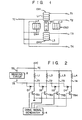
- Fig. 1 is a diagrammatic view showing a stepping motor.
- the stepping motor has a rotor MG comprised of a permanent magnet and four electromagnets EM1 to EM4 arranged at intervals of 90° around the rotor MG.
- the electromagnets EM1 to EM4 have motor coils L1 to L4, respectively, connected at one end to a common terminal TC and at the other end to terminals T1 to T4, respectively.
- Fig. 2 is a circuit diagram showing a stepping motor driving circuit according to one embodiment of this invention which is connected to the motor coils L1 to L4.
- the driving circuit includes npn transistors TR1 to TR4 whose collectors are connected to the terminals T1 to T4, respectively, and whose emitters are connected to ground, a braking circuit 2 having one terminal connected to a common terminal T5 and the other terminal T6 connected to the terminals T1 to T4, through respective diodes D1 to D4, and a drive signal generator 4 for supplying drive signals S1 to S4 to the bases of the transistors TR1 to TR4, respectively.
- the common terminal TC of the. motor coils L1 to L4 is connected to a power source terminal VC.
- the braking circuit 2 includes, as shown in Fig. 3, an npn transistor TR5 having its emitter and collector connected to the terminals T5 and T6, respectively, a resistor R1 connected between the base and emitter of the transistor TR5, a zener diode D5 having its anode and cathode connected to the base and collector, respectively, of the transistor TR5, and an npn phototransistor TR6 having its emitter and collector connected to the base and collector, respectively, of the transistor TR5.
- the phototransistor TR6 constitutes a photocoupler together with a light emitting diode D6 having its anode connected through a resistor R2 and switch SW to a power source terminal VC and its cathode connected to ground.
- the switch SW has its switching position controlled in response to a control signal from, for example, an external control circuit (not shown).
- the attenuation factor of a transient current through one of the motor coils L1 to L4 becomes smaller at a final phase of each stepping motion.
- residual magnetization resulting from the transient current is continuously created, producing a greater braking force.
- An effective impedance between the terminals T5 and T6 varies depending upon the ON or the OFF state of the switch SW. Where the rotor MG is to be driven in stepping fashion at high speed, it is only necessary to increase an effective impedance between the terminals T5 and T6 with the switch SW in the OFF state. On the other hand, where the rotor MG is to be driven in stepping fashion at low speed or is to be stopped, it is only necessary that the impedance between the terminals T5 and T6 be increased with the switch SW in the ON state.
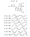
- the drive signal generator 4 supplies drive signals S1 to S4 as shown in Figs. 4A to 4D to the bases of the transistors TR1 to TR4 in response to energizing signals from, for example, the external control circuit (not shown), thus controlling the conduction state of these transistors.
- the drive signal S1 has phase differences of 90°, 180° and 270° with respect to the drive signals S2, S3 and S4, respectively.
- the transistors TR1 to TR4 are rendered conductive in response to the drive signals S1 to S4 of the drive signal generator 4, causing excitation currents as shown in Figs. 4E to 4H to flow through the motor coils L1 to L4. That is, each time one of the drive signals S1 to S4 becomes high, the rotor MG is driven at steps of 90° in synchronism with the drive signal.
- the stepping motor can be stably rotated at high speed by the driving circuit shown in Figs. 2 and 3.
- an energizing signal is supplied from the external control circuit (not shown) to the drive signal generator 4 over a period corresponding to the N number of steps, and at the same time the switch SW is set at the OFF state by a first-level control signal from the external control circuit.
- the rotor MG is driven in stepping fashion at high speed.
- a surge current developed in the motor coil is suppressed by the braking circuit 2 to a sufficiently small value.
- the switch SW is set at the ON state by a second-level control signal from the external control circuit.
- the transient current through one of the motor coils L1 to L4 is slowly attenuated, thus imparting a relatively great braking force to the rotor.
- the rotor MG is driven in stepping fashion at high speed, and can be braked without causing vibrations.
- the light emitting diode D6 and phototransistor TR6 are used to electrically separate a circuit section including the switch SW from a circuit section including the transistor TR5.
- an ordinary transistor can be used in place of the phototransistor and, in this case, the ON state of the transistor can be controlled by a voltage divider circuit comprised of a series circuit of a switching element and resistors.
- a four-phase stepping motor is shown in Fig. 1, a two or more phase stepping motor can be used instead.
Landscapes
- Engineering & Computer Science (AREA)
- Power Engineering (AREA)
- Control Of Stepping Motors (AREA)
Claims (2)
Applications Claiming Priority (2)
| Application Number | Priority Date | Filing Date | Title |
|---|---|---|---|
| JP57150209A JPS5941198A (ja) | 1982-08-30 | 1982-08-30 | ステツピングモ−タ駆動装置 |
| JP150209/82 | 1982-08-30 |
Publications (3)
| Publication Number | Publication Date |
|---|---|
| EP0102471A2 EP0102471A2 (fr) | 1984-03-14 |
| EP0102471A3 EP0102471A3 (en) | 1984-04-25 |
| EP0102471B1 true EP0102471B1 (fr) | 1988-06-15 |
Family
ID=15491910
Family Applications (1)
| Application Number | Title | Priority Date | Filing Date |
|---|---|---|---|
| EP83106385A Expired EP0102471B1 (fr) | 1982-08-30 | 1983-06-30 | Circuit d'entraînement pour moteur pas à pas |
Country Status (4)
| Country | Link |
|---|---|
| US (1) | US4486696A (fr) |
| EP (1) | EP0102471B1 (fr) |
| JP (1) | JPS5941198A (fr) |
| DE (1) | DE3377101D1 (fr) |
Families Citing this family (7)
| Publication number | Priority date | Publication date | Assignee | Title |
|---|---|---|---|---|
| EP0178615A3 (fr) * | 1984-10-19 | 1987-08-05 | Kollmorgen Corporation | Réseaux d'alimentation en courant d'éléments inductifs |
| DE3534601A1 (de) * | 1985-09-27 | 1987-04-02 | Computer Ges Konstanz | Schaltungsanordnung zur ansteuerung eines schrittmotors |
| FR2627312B1 (fr) * | 1988-01-29 | 1994-02-18 | Canon Kk | Enregistreur de donnees |
| US4983902A (en) * | 1989-11-01 | 1991-01-08 | Sundstrand Corporation | Fast current discharging switch for a variable reluctance motor drive |
| ATE450078T1 (de) * | 1999-04-12 | 2009-12-15 | Talaris Holdings Ltd | Schrittmotor mit einer elektrischen ansteuerschaltung sowie anordnung mit einem schrittmotor |
| US6998805B2 (en) * | 2003-05-09 | 2006-02-14 | Aruze Corp. | Motor stop control device |
| US7231139B2 (en) * | 2005-08-29 | 2007-06-12 | Asahi Kasei Microsystems Co., Ltd. | Digital noise reduction for motors |
Family Cites Families (4)
| Publication number | Priority date | Publication date | Assignee | Title |
|---|---|---|---|---|
| US4164697A (en) * | 1976-04-08 | 1979-08-14 | Texas Instruments Incorporated | Method and system for squelching decaying current in motor phases |
| US4129816A (en) * | 1977-08-10 | 1978-12-12 | Teletype Corporation | Stepping motor control circuit |
| JPS55133700A (en) * | 1979-04-04 | 1980-10-17 | Canon Inc | Driver for pulse motor |
| JPS56117598A (en) * | 1980-02-22 | 1981-09-16 | Canon Inc | Driving device for pulse motor |
-
1982
- 1982-08-30 JP JP57150209A patent/JPS5941198A/ja active Pending
-
1983
- 1983-06-24 US US06/508,066 patent/US4486696A/en not_active Expired - Fee Related
- 1983-06-30 EP EP83106385A patent/EP0102471B1/fr not_active Expired
- 1983-06-30 DE DE8383106385T patent/DE3377101D1/de not_active Expired
Also Published As
| Publication number | Publication date |
|---|---|
| JPS5941198A (ja) | 1984-03-07 |
| US4486696A (en) | 1984-12-04 |
| EP0102471A3 (en) | 1984-04-25 |
| DE3377101D1 (en) | 1988-07-21 |
| EP0102471A2 (fr) | 1984-03-14 |
Similar Documents
| Publication | Publication Date | Title |
|---|---|---|
| US3942083A (en) | Brushless motor | |
| US4051417A (en) | Control system for a brushless motor | |
| US4740734A (en) | Control apparatus for brushless dc motors | |
| US5063339A (en) | Stepping motor driving device | |
| EP0102471B1 (fr) | Circuit d'entraînement pour moteur pas à pas | |
| JPH0711262B2 (ja) | 燃料ポンプ駆動システム | |
| WO1990016111A1 (fr) | Dispositif de commande d'un moteur a reluctance | |
| US4242624A (en) | Direct current stepper motor with a permanent magnet rotor and electronic commutation device | |
| US5541487A (en) | Driving circuit for stepping motor | |
| US4027212A (en) | Three phase full wave DC motor decoder | |
| US5079487A (en) | Anti-backdrive commutation of brushless DC motors | |
| US4458191A (en) | Step motor drive circuit | |
| EP0511990B1 (fr) | Dispositif permettant de commander l'alimentation en energie electrique d'un moteur pas a pas et moteur de ce type muni d'un tel dispositif | |
| US4490663A (en) | Device for driving a stepping motor | |
| US4277732A (en) | Low power stepping motor driver circuit and method | |
| US4450394A (en) | Stepper motor drive circuit | |
| US4673856A (en) | Stepping motor drive circuit | |
| EP0060143B1 (fr) | Moteur électrique | |
| JPH0243436B2 (fr) | ||
| JPS6223280Y2 (fr) | ||
| JPS5866600A (ja) | パルスモ−タの駆動装置 | |
| JP2788589B2 (ja) | ブラシレスモータの駆動回路 | |
| JP2834773B2 (ja) | モータの速度制御回路 | |
| JPH0239196B2 (fr) | ||
| JPH0334688B2 (fr) |
Legal Events
| Date | Code | Title | Description |
|---|---|---|---|
| PUAI | Public reference made under article 153(3) epc to a published international application that has entered the european phase |
Free format text: ORIGINAL CODE: 0009012 |
|
| PUAL | Search report despatched |
Free format text: ORIGINAL CODE: 0009013 |
|
| 17P | Request for examination filed |
Effective date: 19830630 |
|
| AK | Designated contracting states |
Designated state(s): DE FR GB |
|
| AK | Designated contracting states |
Designated state(s): DE FR GB |
|
| GRAA | (expected) grant |
Free format text: ORIGINAL CODE: 0009210 |
|
| AK | Designated contracting states |
Kind code of ref document: B1 Designated state(s): DE FR GB |
|
| REF | Corresponds to: |
Ref document number: 3377101 Country of ref document: DE Date of ref document: 19880721 |
|
| ET | Fr: translation filed | ||
| PLBE | No opposition filed within time limit |
Free format text: ORIGINAL CODE: 0009261 |
|
| STAA | Information on the status of an ep patent application or granted ep patent |
Free format text: STATUS: NO OPPOSITION FILED WITHIN TIME LIMIT |
|
| 26N | No opposition filed | ||
| PGFP | Annual fee paid to national office [announced via postgrant information from national office to epo] |
Ref country code: FR Payment date: 19930514 Year of fee payment: 11 |
|
| PGFP | Annual fee paid to national office [announced via postgrant information from national office to epo] |
Ref country code: GB Payment date: 19930618 Year of fee payment: 11 |
|
| PGFP | Annual fee paid to national office [announced via postgrant information from national office to epo] |
Ref country code: DE Payment date: 19930830 Year of fee payment: 11 |
|
| PG25 | Lapsed in a contracting state [announced via postgrant information from national office to epo] |
Ref country code: GB Effective date: 19940630 |
|
| PG25 | Lapsed in a contracting state [announced via postgrant information from national office to epo] |
Ref country code: FR Effective date: 19950228 |
|
| GBPC | Gb: european patent ceased through non-payment of renewal fee |
Effective date: 19940630 |
|
| PG25 | Lapsed in a contracting state [announced via postgrant information from national office to epo] |
Ref country code: DE Effective date: 19950301 |
|
| REG | Reference to a national code |
Ref country code: FR Ref legal event code: ST |