EP0102569A2 - Vorrichtung für elektrische Korona entladung, Verfahren zu ihrer Herstellung und elektrostatisches Behandlungsgerät mit einer solchen Vorrichtung - Google Patents
Vorrichtung für elektrische Korona entladung, Verfahren zu ihrer Herstellung und elektrostatisches Behandlungsgerät mit einer solchen Vorrichtung Download PDFInfo
- Publication number
- EP0102569A2 EP0102569A2 EP83108152A EP83108152A EP0102569A2 EP 0102569 A2 EP0102569 A2 EP 0102569A2 EP 83108152 A EP83108152 A EP 83108152A EP 83108152 A EP83108152 A EP 83108152A EP 0102569 A2 EP0102569 A2 EP 0102569A2
- Authority
- EP
- European Patent Office
- Prior art keywords
- electric field
- field device
- electrode
- object matter
- electrodes
- Prior art date
- Legal status (The legal status is an assumption and is not a legal conclusion. Google has not performed a legal analysis and makes no representation as to the accuracy of the status listed.)
- Granted
Links
Images


Classifications
-
- H—ELECTRICITY
- H05—ELECTRIC TECHNIQUES NOT OTHERWISE PROVIDED FOR
- H05F—STATIC ELECTRICITY; NATURALLY-OCCURRING ELECTRICITY
- H05F3/00—Carrying-off electrostatic charges
- H05F3/04—Carrying-off electrostatic charges by means of spark gaps or other discharge devices
-
- D—TEXTILES; PAPER
- D06—TREATMENT OF TEXTILES OR THE LIKE; LAUNDERING; FLEXIBLE MATERIALS NOT OTHERWISE PROVIDED FOR
- D06M—TREATMENT, NOT PROVIDED FOR ELSEWHERE IN CLASS D06, OF FIBRES, THREADS, YARNS, FABRICS, FEATHERS OR FIBROUS GOODS MADE FROM SUCH MATERIALS
- D06M10/00—Physical treatment of fibres, threads, yarns, fabrics or fibrous goods made from such materials, e.g. by ultrasonic waves, corona discharge, irradiation, electric currents or magnetic fields; Physical treatment combined with treatment with chemical compounds or elements
- D06M10/02—Sonic or ultrasonic waves; Corona discharge
- D06M10/025—Corona discharge or low temperature plasma
-
- B—PERFORMING OPERATIONS; TRANSPORTING
- B03—SEPARATION OF SOLID MATERIALS USING LIQUIDS OR USING PNEUMATIC TABLES OR JIGS; MAGNETIC OR ELECTROSTATIC SEPARATION OF SOLID MATERIALS FROM SOLID MATERIALS OR FLUIDS; SEPARATION BY HIGH-VOLTAGE ELECTRIC FIELDS
- B03C—MAGNETIC OR ELECTROSTATIC SEPARATION OF SOLID MATERIALS FROM SOLID MATERIALS OR FLUIDS; SEPARATION BY HIGH-VOLTAGE ELECTRIC FIELDS
- B03C7/00—Separating solids from solids by electrostatic effect
- B03C7/02—Separators
- B03C7/04—Separators with material carriers in the form of trays, troughs, or tables
-
- B—PERFORMING OPERATIONS; TRANSPORTING
- B05—SPRAYING OR ATOMISING IN GENERAL; APPLYING FLUENT MATERIALS TO SURFACES, IN GENERAL
- B05B—SPRAYING APPARATUS; ATOMISING APPARATUS; NOZZLES
- B05B5/00—Electrostatic spraying apparatus; Spraying apparatus with means for charging the spray electrically; Apparatus for spraying liquids or other fluent materials by other electric means
- B05B5/025—Discharge apparatus, e.g. electrostatic spray guns
- B05B5/03—Discharge apparatus, e.g. electrostatic spray guns characterised by the use of gas, e.g. electrostatically assisted pneumatic spraying
- B05B5/032—Discharge apparatus, e.g. electrostatic spray guns characterised by the use of gas, e.g. electrostatically assisted pneumatic spraying for spraying particulate materials
-
- B—PERFORMING OPERATIONS; TRANSPORTING
- B05—SPRAYING OR ATOMISING IN GENERAL; APPLYING FLUENT MATERIALS TO SURFACES, IN GENERAL
- B05B—SPRAYING APPARATUS; ATOMISING APPARATUS; NOZZLES
- B05B5/00—Electrostatic spraying apparatus; Spraying apparatus with means for charging the spray electrically; Apparatus for spraying liquids or other fluent materials by other electric means
- B05B5/025—Discharge apparatus, e.g. electrostatic spray guns
- B05B5/043—Discharge apparatus, e.g. electrostatic spray guns using induction-charging
-
- B—PERFORMING OPERATIONS; TRANSPORTING
- B05—SPRAYING OR ATOMISING IN GENERAL; APPLYING FLUENT MATERIALS TO SURFACES, IN GENERAL
- B05B—SPRAYING APPARATUS; ATOMISING APPARATUS; NOZZLES
- B05B5/00—Electrostatic spraying apparatus; Spraying apparatus with means for charging the spray electrically; Apparatus for spraying liquids or other fluent materials by other electric means
- B05B5/08—Plant for applying liquids or other fluent materials to objects
- B05B5/087—Arrangements of electrodes, e.g. of charging, shielding, collecting electrodes
- B05B5/088—Arrangements of electrodes, e.g. of charging, shielding, collecting electrodes for creating electric field curtains
-
- B—PERFORMING OPERATIONS; TRANSPORTING
- B65—CONVEYING; PACKING; STORING; HANDLING THIN OR FILAMENTARY MATERIAL
- B65G—TRANSPORT OR STORAGE DEVICES, e.g. CONVEYORS FOR LOADING OR TIPPING, SHOP CONVEYOR SYSTEMS OR PNEUMATIC TUBE CONVEYORS
- B65G54/00—Non-mechanical conveyors not otherwise provided for
- B65G54/02—Non-mechanical conveyors not otherwise provided for electrostatic, electric, or magnetic
-
- G—PHYSICS
- G03—PHOTOGRAPHY; CINEMATOGRAPHY; ANALOGOUS TECHNIQUES USING WAVES OTHER THAN OPTICAL WAVES; ELECTROGRAPHY; HOLOGRAPHY
- G03G—ELECTROGRAPHY; ELECTROPHOTOGRAPHY; MAGNETOGRAPHY
- G03G15/00—Apparatus for electrographic processes using a charge pattern
- G03G15/06—Apparatus for electrographic processes using a charge pattern for developing
- G03G15/08—Apparatus for electrographic processes using a charge pattern for developing using a solid developer, e.g. powder developer
- G03G15/0822—Arrangements for preparing, mixing, supplying or dispensing developer
-
- H—ELECTRICITY
- H01—ELECTRIC ELEMENTS
- H01T—SPARK GAPS; OVERVOLTAGE ARRESTERS USING SPARK GAPS; SPARKING PLUGS; CORONA DEVICES; GENERATING IONS TO BE INTRODUCED INTO NON-ENCLOSED GASES
- H01T19/00—Devices providing for corona discharge
Definitions
- the present invention relates to various types of electric field devices employing fine ceramic dielectrics and a method for making the devices as well as an electrostatic treatment apparatus of object matters making use of the electric field device.
- Electrodes in which electrodes are provided on a surface of or within a dielectric body, a D.C. high voltage or an A.C. high voltage (including a sinusoidal wave, a rectangular wave, and a pulse-shaped high voltage) are applied between these electrodes to produce phenomena inherent to an electric field such as gaseous discharge or electro-mechanical phenomena, have been in themselves well known, and these phenomena are utilized as an ion source for charging or discharging of object matters or utilized for electro-mechanical operations such as adhesion, repulsion or transportation of object matters caused by an electric force (hereinafter generally called "electric field device").
- electric field device hereinafter generally called "electric field device”
- Examples of the electric field devices serving as an ion source have been disclosed in Japanese patent or copending Japanese patent applications entitled at the old time "DENKITEKI GASU SEISEI SOCHI (Electric Gas Refining Device)" (Japanese Patent No. 99242), and recently “SEIDEN FUNTAI TOCHAKU SOCHI (Electrostatic Powder Painting Device)” (Japanese Patent Application No. 51-103328), “RYUSHI KADEN SOCHI (Particle Charging Device)” (Japanese Patent Application No. 52-106400), “ J ODEN SOCHI (Charge Removing Device)” (Japanese Patent Application No.
- the electric field device had a very short life and a high cost, and the way of widely utilizing the electric field device has been closed.
- One object of the present invention is to provide an electrostatic treatment apparatus of object matters which makes use of a long-life, highly reliable and less expensive electric field device or devices which are free from the above-described difficulties, and to make it possible to bring the electrostatic treatment apparatus into really practical use.
- the aforementioned object is achieved by making an electric field device which is dense, mechanically electrically chemically and thermally durable and highly reliable through the steps of employing highly pure and mechanically electrically chemically and thermally extremely durable ceramic materials such as, for example, a high purity alumina porcelain or the like (hereinafter called "fine ceramic") as a dielectric material, disposing electrodes on the shaped material before sintering and sintering the shaped material integrally with the electrodes, and by using the made electric field device or devices in an electrostatic treatment apparatus of object matter.
- ceramic materials such as, for example, a high purity alumina porcelain or the like (hereinafter called "fine ceramic"
- a method in which when, for instance, high purity alumina porcelain is used, alumina preliminarily ground into powder having a grain diameter of several microns or less is bound by means of an organic binder, then a raw material sheet formed in a layer shape (called "green sheet") is produced, on the surface of the green sheet are formed electrodes by making use of an ink in which micro-fine powder of appropriate metal, for example, tungsten is dispersed with a thick film printing technique such as, for example, screen printing technique, the thus formed green sheet associated with electrode in itself singly, or after a plurality of such green sheets have been stacked and press-bonded, the formed multi- layer green sheet, is sintered within an appropriate reducing atmosphere such as a hydrogen furnace at a high temperature in the proximity of 1500°C.
- an appropriate reducing atmosphere such as a hydrogen furnace at a high temperature in the proximity of 1500°C.
- the electric field device by making the electric field device from a multilayer green sheet, it becomes possible to dispose a part of the electrodes as embedded in a sandwich form within the fine-ceramic dielectric in a single layer or in multiple layers, and thereby it becomes possible to achieve a high degree of electric field effect or ion formation effect, or to enhance a safety by internally embedding an electrode to be applied with a hogh voltage.
- fine ceramic dielectric material to be used according to the present invention highly pure alumina porcelain having a purity of 90% or higher is preferable, but even among materials other than that material, any fine ceramic material could be employed so long as it is mechanically, electrically, chemically and thermally durable.
- any fine ceramic material could be employed so long as it is mechanically, electrically, chemically and thermally durable.
- an electric field device is formed in a multilayer structure, it is possible to make it less expensive or to enhance its performance by using a high purity alumina porcelain layer and an alumina porcelain layer having a relatively low purity and hence being less expensive in combination, by using fine ceramic materials of different kinds having different natures in different layers or at different locations in combination, or by using a fine ceramic material and the other dielectric materials (synthetic resin, mica, glass, ERP) in different layers or at different locations in combination.
- synthetic resin, mica, glass, ERP synthetic resin, mica, glass, ERP
- the electric field device may be subjected to improvement in the nature of the surface such as smoothening of the surface or creation of electrical conductivity by applying a suitable glaze on the surface, and in addition, the electric field device can be subjected to improvements in its surface nature by depositing a Teflon layer, a silicon layer and a surface layer of another appropriate material.
- a high melting point metal that is easily integrated with the fine ceramic material used as a base material when they are sintered together and that has a coefficient of thermal expansion as close as that of the fine ceramic material, is preferable, and when the base material is high purity alumina porcelain, tungsten is most suitable.
- every suitable metallic material can be selectively used, Upon deposition of"the electrode material onto the green sheet, although a thick film electrode could be formed through the technique of screen printing or the like with metal powder dispersed ink, in some cases a metallic electrode which has been preliminarily formed into a wire shape, a sheet shape or a foil shape could be deposited.
- a thin film electrode deposited by vapor-deposition or the like also can be used.
- the electrode material is not always limited to a metallic material, but as a matter of course, every suitable material such as carbon fibers, semiconductor ceramic material or the like can be used.
- the electrode material could have its surface plated with appropriate metal such as nickel for the purpose of preventing oxidation, protecting its surface or facilitating soldering, and moreover on the electrode itself could be thinly applied a glaze layer, an alumina insulator film or another surface layer.
- the novel electric field device can be formed and used not only in a plane shape but also in an arbitrary curved surface shape (spherical shape, semi-cylindrical shape, circular column shape, polygonal shape, step-like shape, etc.), and when practicing such a curved surfae shape, in the stage of a green sheet associated with electrodes which is still rich in flexibility, the green sheet could be shaped into a desired configuration and then sintered.
- the field of application of the electric field device according to the present invention extends over every one of charging and/or discharging apparatuses of object matters and electro-mechanical operation apparatuses of object matters, also the field of application involves all the subject matters of the Japanese patents and copending Japanese patent applications as referred to in the beginning of this specification, and furthermore, it involves all the methods and apparatuses for application of the electric field device which will appear in the future.
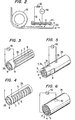
- Figs. lA to IF show one preferred embodiment of an electric field device according to the present invention that is operable as an ion source.
- These figures show a method for making an electric field device, in which a group of elongated corona discharge electrodes are disposed on a rectangular fine ceramic dielectric plate in its lengthwise direction, a sheet of induction electrode having a size opposed to the whole of said corona discharge electrode group is embedded within the dielectric plate under the corona discharge electrode group, and then the entire assembly is sintered according to the present invention.
- 1A is a perspective view showing a top surface of an upper green sheet, in which on an upper surface 2 of the rectangular upper green sheet 1 are formed a plurality of parallel corona electrodes 3, 4 and 5 directed in the lengthwise direction of about 1 mm in width and about 100 ⁇ m in thickness at an interval of about 5 mm with ink having tungsten micro-fine powder dispersed therein through a screen printing technique, further these electrodes are connected to a common conductor 6 printed through a similar method, and then a terminal conductor 7 is further connected by printing.
- Fig. 1B is a perspective view showing a lower surface 8 of the above-described upper green sheet 1, in which a rectangular planar induction electrode 9 is formed on the lower surface portion opposed to the entire area of the upper surface occupied by the electrodes 3, 4 and 5 by printing with ink having tungsten micro-fine powder dispersed therein through a similar screen printing technique.
- Fig. 1B is a perspective view showing a lower surface 8 of the above-described upper green sheet 1, in which a rectangular planar induction electrode 9 is formed on the lower surface portion opposed to the entire area of the upper surface occupied by the electrodes 3, 4 and 5 by printing with ink having tungsten micro-fine powder dispersed therein through a similar screen printing technique.
- 1C is a perspective view showing an upper surface 11 of a lower sheet 10, in which a hole 12 of about 1 mm in diameter is opened at the center of the same sheet 10 penetrating therethrough, this hole is filled with ink having tungsten micro-fine powder dispersed therein to form a conductor penetrating through the sheet 10, and further a disc-shaped contacting conductor portion 13 of about 10 mm in diameter with the hole 12 located at its center, is formed by screen printing similarly with ink having tungsten micro-fine powder dispersed therein.
- a terminal conductor 7a to be connected with the terminal conductor 7.
- 1D is a perspective view showing a lower surface 14 of the lower sheet 10, in which a disc-shaped terminal conductor portion 15 of about 10 mm in diameter with the aforementioned hole 12 filled with ink having tungsten micro-fine powder dispersed therein located at its center, is formed by screen printing similarly with ink having tungsten micro-fine powder dispersed therein.
- a disc-shaped terminal conductor portion 15 of about 10 mm in diameter with the aforementioned hole 12 filled with ink having tungsten micro-fine powder dispersed therein located at its center is formed by screen printing similarly with ink having tungsten micro-fine powder dispersed therein.
- another disc-shaped terminal conductor portion 16 of about 10 mm in diameter by screen printing similarly with ink having tungsten micro-fine powder dispersed therein, and this terminal conductor portion 16 is connected to the terminal conductor 7a through a terminal conductor 17 printed with similar ink.
- aforementioned respective sheets 1 and 10 are superposed, and after they have been shaped by hot press bonding, they are sintered within a hydrogen furnace. Then they are sintered with the planar induction electrode 9 airtightly sandwiched between the respective sheets 1 and 10, and the electrode 9 can be embedded within a dielectric plate 18 which has been integrally sintered from the upper and lower sheets. And the aforementioned induction electrode 9 is fused jointly with the disc-shaped terminal conductor portion 13 and is connected to the disc-shaped terminal conductor portion 15 on the rear surface of the dielectric plate 18 as conducting through the hole 12.
- Fig. lE is a perspective view showing electrode surfaces of an electric field device serving as an ion source which was fabricated in the above-described manner, in which a ceramic plate portion made of the upper green sheet is partly cut away to show a ceramic plate portion made of the lower green sheet and the induction electrode 9.
- Fig. IF shows a cross-section view of this electric field device.
- the surfaces of the electrodes 3, 4 and 5, the conductors 6, 7, 7a and 17 and the terminal conductor portions 15 and 16 are plated by nickel in order to prevent oxidation of tungsten, and thereby soldering of external conductors to 1 the terminal conductor portions 15 and 16 is facilitated. If a high frequency A.C. high voltage is applied from a high frequency A.C.
- the high voltage source 19 via the terminal conductor portions 15 and 16 not shown between the corona electrode group 3, 4 and 5 and the planar induction electrode 9 by the intermediary of the fine ceramic dielectric layer 20 (the electrodes 3, 4 and 5 being grounded for the purpose of safety), then high frequency corona discharge is generated from the edges of the electrodes 3, 4 and 5 along the surface of the dielectric plate 18, and thereby plasma containing plenty of positive and negative ions is formed. Accordingly, if this device is brought close to a proximity of a charged body, ions of the opposite polarity to that charge are supplied from this plasma to the aforementioned charged body, and thereby the charged body can be quickly discharged. In order words, the device can be used as a discharger or a charge remover. In this case, as a matter of course, repetitive pulse voltages could be applied by employing a pulsed high voltage source in place of the high frequency A.C. high voltage source 19.
- Fig. 2 shows one example in which the ion source electric field device 21 in Fig. 1F is utilized to remove electric charge charged by friction on a rubber belt 23 after passing around a roller 22, in which the ion source electric field device 21 is disposed in the close proximity of a charged rubber belt surface, and in the illustrated example, negative ions are attracted from the plasma formed by the corona electrode group 3, 4 and 5 to neutralize the positive charge on the rubber belt surface.
- Reference numeral 24 designates a protective resistor.
- Fig. 3 shows a ion source constructed by bending the upper sheet 1 shown in Figs. 1A and 1B about an axis directed in the lengthwise direction of the sheet so that the upper surface of the green sheet 1 may come outside to form a hollow cylinder 25, and then sintering the hollow cylinder-shaped green sheet.
- a high frequency A.C. high voltage source 19 is connected to the thin wire-shaped corona discharge electrodes 3, 4 and 5 which are arrayed on the outer cylindre surface in the lengthwise direction in parallel to each other and at equal intervals and the induction electrode 9 formed in a cylindrical surface shape on the inner cylindre surface as shown in Fig. 3 and then a high frequency A.C.
- an electric field device 26 serving as a cylindrical plasma ion source can be constructed.
- the thin wire-shaped corona discharge electrodes 3, 4 and 5 could be disposed on the cylinder surface so as to be perpendicular to generating lines.
- Fig. 4 shows such modification.
- Fig. 5 shows an ion source constructed by superposing the upper sheet shown in Figs. lA and 1B and the lower sheet shown in Figs. lC and 1D wiht each other, stacking and press- bonding them into the shape shown in Fig. lE, thereafter bending the assembly about an axis directed in the lengthwise direction of the sheets so that the upper surface having the thin wire-shaped corona discharge electrodes 3, 4, 5, ... may come inside to form a hollow cylinder 26, and then sintering the hollow cylinder-shaped green sheet. If a high frequency A.C. high voltage is applied between the thin wire-shaped corona discharge electrodes 3, 4, 5, ...
- Fig. 6 shows one modification of the device shown in Fig. 5, in which thin wire-shaped corona discharge electrodes 3, 4, 5, ... are arrayed on an inner surface of a hollow cylinder 26 in the direction perpendicular to the axis of the cylinder.
- the cylinder-shaped electric field device shown in Figs. 5 and 6 can be used for removing electric charge of a liquid which has been charged by friction with a pipe by interposing the device in the midway of a pipe line conveyor of a liquid having a high resistance.
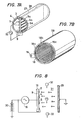
- Fig. 7A shows one example of application of electric field devices 27 each of which employs its both surfaces as ion sources by providing thin wire-shaped corona discharge electrodes 3a, 4a, 5a, ... also on the lower surface of the fine ceramic dielectric plate 18 shown in Figs. lE and 1F as directed in the lengthwise direction.
- the electric field device 27 is directly inserted and disposed within a conveyor pipe line 28 for pulverized or granular material having a high resistance or a liquid having a high resistance to remove electric charge from the pulverized or granular material or the liquid.
- the electric field devices shown in Fig. 3 or 4 also can be used, and in that case, in place of the planar ion source electric field device 27, these cylindrical ion source electric field devices are disposed in the proximity of the center axis of the conveyor pipe line 28 along the center axis.
- Fig. 7B shows another example of application of the electric field devices, in which a large number of electric field devices 18, 18a, 18b, 18c, notably servicing as ion sources as illustrated in Figs. lE and 1F are disposed on an inner wall surface of a conveyor pipe line 28 for pulverized or granular material or a high resistance liquid so as cover a part or whole of the inner wall surface, and electric charge is removed from the aforementioned pulverized or granular material or high resistance liquid which has been charged by friction with the pipeline on the upstream side. by means of the plasma produced by the electric field devices.
- Fig. 8 shows one example in which the planar ion source electric field device 18 shown in Figs. lE and 1F is used as a charging apparatus, in which the electric field device 18 is insulatively supported in opposition to a grounded non-corona electrode 29 so that the corona discharge electrodes 3, 4, 5, ... may be opposed to the non-corona electrode 29, and after a plasma has been produced from the corona electrodes 3, 4, 5, ... by applying a high frequency high voltage from a high frequency A.C. high voltage source 19 between the corona discharge electrodes 3, 4, 5, ... and the embedded induction electrode 9, if the corona discharge electrodes 3, 4, 5, ... are connected to a negative D.C.
- Fig. 9 shows one example by application of the electric field device, in which negative ions are given to a surface of a grounded photo-sensitive roller 34 having a photoconductive coating film on its surface, which is used in an electronic photography, by making use of the cylinder-shaped ion source electric field devices 26 shown in Fig. 3 or 4. Since these ion sources can produce quite plenty of negative ions uniformly, they can put negative ions on a photoconductive film 35 on the surface of the roller 34 uniformly within a short period of time.
- reference numeral 19 designates a high frequency A.C. high voltage source
- numeral 30 designates a negative D.C. high voltage source, and since the effects of these voltage sources are self-explanatory, there is no need to add special explanation thereon.
- Reference numeral 26a in Fig. 9 is a similar cylindrical ion source electric field device, in which corona discharge electrodes 3, 4, 5, ... are grounded, so that positive ions supplied from plasma formed by this electric field device can remove remaining negative ions on the roller 34.
- Reference numeral 19a also designates a high frequency A.C. high voltage source.
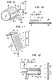
- Fig. 10 shows one example of application of electric field device according to this invention wherein a charging ion source electric field device 18 is employed for giving negative charge to a surface of insulating film 36 disposed on a grounded non-corona electrode 29, thereby the film 36 is intensely adhered to said non-corona electrode 29 due to electric force.
- the electric field device 18 is moved in the direction of arrow 37.
- the electric field device 18 acts as discharger which removes the surface charges of film 36 and enables said film 36 to be detached from said non-corona electrode 29.
- Fig. ll illustrates an example of employing a charging ion source electric field device 18, as shown by Fig. 8, in a powder painting apparatus.
- the charging ion source electric field device 18 is disposed to confront a suspended, grounded substrate 38.
- a D.C. high voltage source 30 is used to run negative ions from said plasma toward said substrate 38.
- a powder is concurrently fed from above to the surface of electric field device 18 by way of a pipe line 39 and a slit 41 of triangular - formed feeder 18. Thereupon, said powder is negatively charged due to bombardment by negative ions and is carried by electric force toward the substrate 38 to coat a surface thereof.
- Fig. 12 shows an example of application in which an annular ion source electric field device 42 is composed of fine ceramic dielectric in accordance with this invention and a powder painting apparatus is constructed by mounting the formed device 42 on the forward end of a hand gun for powder painting.
- the device 42 is shaped as an annular fine ceramic dielectric body with the longitudinal section of rectangle.
- Said device 42 has been made so as to have an annular induction electrode 43 embedded therein and an annular thick film-shaped corona discharge electrode 44 of tungsten at the front thereof, according to the producing methods as illustrated by Figs. 1A to 1F in detail.
- Thus-formed fine ceramic body is aligned with an annular opening 46 and attached to the front end of a hand gun 45 made of plastic.
- Figs. 13A to 13E illustrate one embodiment of the electric field device according to this invention.
- This embodiment corresponds to "three-phase contact type electric field curtain device" as the most typical electric field device for electromechanical operation apparatus.
- three green sheets 50, 51, 52 are employed three green sheets 50, 51, 52 as three layers.
- Fig. 13A is a perspective view of very thin surface layer green sheet 50 having a thickness of about 0.1 - 0.5 mm when viewed from above sideways. This sheet has no printed electrode.
- Fig. 13B is a perspective view of the upper surface of rectangular intermediate layer sheet 51 having a thickness of about 2 mm. On the upper surface, many parallel narrow strip electrodes 53, 54, 55, 53a, 54a, 55a, 53b, 54b, 55b, ...
- Electrodes are disposed by screen printing technique with tungsten micro-fine powder dispersion ink. They are of about 1 mm in width and about 0.1 mm in thickness, and are arranged at right angles to the longitudinal direction if the sheet 51 with equal intervals of about 5 mm. Every third electrode of them is connected to one another to form three electrode groups u, v and w, consisting of electrodes, 53 - 53a - 53b ..., 54 - 54a - 54b ... and 55 - 55a - 55b ..., respectively.
- the u, v and w phase voltages of a three - phase A.C. high voltage will be applied to respective electrode groups.
- three connecting conductors 56, 57 and 58 parallel to lengthwise direction of sheet are screen printed on the back surface of intermediate layer sheet 51 in the same manner, and the conductor 56 is connected to u-phase group of electrodes 53, 53a, 53b ... on the upper surface of intermediate layer sheet 51 by way of small holes 59, 59a, 59b ... which penetrate through sheet 51 and are filled with tungsten micro-fine powder dispersion ink, as shown in Fig. 13C.
- the conductor 57 is connected to v-phase group of electrodes 54, 54a, 54b ... on the upper surface of intermediate layer sheet 51 by way of similar small holes 60, 60a, 60b ....
- the conductor 58 is connected to w-phase group of electrodes 55, 55a, 55b ... on the upper surface of intermediate layer sheet 51 by way of similar small holes 61, 61a, 6rb ....
- the connecting conductors 56, 57, 58 constitute conducting means for applying u-phase, v-phase and w-phase voltages of a three-phase A.C. high voltage to u-phase group of electrodes, v-phase group of electrodes and w-phase group of electrodes, respectively.
- Fig. 13D is a perspective view of the upper surface of a base layer green sheet 52 of 3 mm in thickness
- Fig. 13E is a perspective view of the rear surface thereof.
- Reference numerals 62a, 63a and 64a designate small holes which penetrate the sheet 52 and are filled with tungsten powder dispersion ink.
- disc-shaped contacting conductor parts 62, 63, 64 of about 10 mm in diameter on the upper surface and disc-shaped terminal conductor parts 66, 67, 68 of about 10 mm in diameter on the rear surface.
- Each of said conductor parts has been screen printed with tungsten powder dispersion ink.
- the combinations 62 - 66, 63 - 67 and 64 - 68 are positioned so as to be connected by contact to conductors 56, 57 and 58, respectively.
- a three-phase contact type electric field curtain device 69 As shown by Fig. 14, is completed.
- this device there are provided three-phase electrode groups u, v and w inserted in fine ceramic matrix, beneath a smooth thin fine ceramic layer, and, under said electrodes, connecting conductors 56, 57 and 58 embedded in the same fine ceramic matrix, which are connected to u-phase, v-phase and w-phase electrode groups.
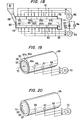
- high voltage source 70 are applied to three-phase electrode groups of this electric field curtain device 69 in the sequence u-phase, v-phase, w-phase by way of terminal conductor parts 66, 67, 68, as shown by a schematic diagram of a model in Fig. 15, a progressive wave non-uniform electric field which travels in the phase sequence direction, as shown by arrow 72, along surface 71 of device 69 is generated. Consequently, if particles of a powder are placed on the surface 71 of device 69, they are charged by contact with the surface and then violently repelled and floated from the surface due to the action of said progressive wave non-uniform electric field. They are conveyed in floating state in the direction of arrow 72.
- the most important electromechanical actions to a powder of this three-phase contact type electric field curtain device consist in these charging by contact, repelling and transporting.
- this electric field device can be utilized for preventing the adherence and the accumulation of powder and for transporting a powder. If the value of a impressed three-phase A.C. high voltage is being increased, a kind of electrodeless A.C. corona discharge is generated above a certain critical value of voltage Vc and the air on the surface is electrically dissociated to produce positive and negative ions. In this situation, the above-mentioned electromechanical actions, such as repelling and transporting, become more vigorous.
- a vigorous A.C. corona discharge generates around surfaces exposed to air of metal electrode group of 53, 53a, 53b ..., even if at relatively low voltage, and said repelling and transporting actions are promoted.
- This device is referred to as one-phase-exposed type.
- modifications of the device in Fig. 16, that is, devices wherein two phase electrode groups or all three phase groups are exposed are also employable.
- a so-called single-phase contact type electric field curtain device 75 which has single-phase electrodes 73, 74, 73a, 74a ... as shown in Fig. 17A or Fig. 17B, in place of three-phase electrodes.
- a single-phase A.C. high voltage from a single-phase A.C. high voltage source 78 is applied between the electrode group 73 - 73a - 73b ... and the electrode group 74 - 74a - 74b ..., each electrode member of one group being adjacent to electrode members of the other group, by way of terminal conductor parts 76 and 77, as shown by Figs.
- standing wave A.C. non-uniform electric field are generated among these electrodes, and particles of powder on the surface 71 of device 75 are charged by contact and repelled violently to float.
- a single-phase contact type electric field curtain device 75 has a remarkable repelling action to charged particles as mentioned above, but generally has no transporting action.
- the device of Fig. 17B wherein one group of phase electrodes 73, 73a ... are arranged on the surface 71 to expose to the atmosphere is of one-phase-exposed type and generates a vigorous A.C. corona discharge at a relatively low voltage to promote remarkably said repelling action, as well.
- a single-phase contact type electric field curtain device in which all electrodes are exposed as modification of device in Fig. 17A or 17B is operable.
- Single-phase contact type electric field curtain devices of all these types can be employed in constructing pipe lines for transporting a pulverized or granular material and in lining inner walls of powder painting booth for sweeping off adhered particles or preventing adhesion of particles.
- these single-phase contact type electric field curtain devices are disposed obliquely, particles of pulverized or granular material placed on devices are subject to vigorous agitating and floating action and slide downwards along the surface of the device due to gravity. Therefore, the devices can be utilized for conveying pulverized or granular material.
- changes in connection enable the use of a multi-phase A.C. source in place of three-phase A.C. source 70.
- a multi-phase A.C. source can be used.
- electrodes to be exposed should be exchanged depending on change in phases.
- a thin insulating alumina layer which has been formed by applying a finely divided alumina dispersion ink onto an intermediate layer sheet by screen printing and then have been sintered can be employed.
- the surface layer 50 can be made especially thin.
- Fig. 18 shows an example of application wherein three-phase contact type electric field curtain device as one of electric devices of this invention is utilized to compose a conveyor machine for pulverized or granular material.
- An underside surface 80 and an upside surface 81 of inner wall of a flume 79 having rectangular horizontal section are paved with a number of plate form three-phase contact type electric field curtain devices 82, 82a, 82b ... and 83, 83a, 83b ... which have been shown in Fig. 15 or 16.
- Three-phase A.C.-high voltages from three-phase A.C. high voltage sources 84, 85 are applied to the respective group of devices and progressive wave non-uniform electric fields which travel in the phase sequence direction as shown by arrow 86 are generated.
- a single-phase A.C. high voltage source 94 is connected between neutral points 90, 91 in place of D.C. high voltage source 92 by changing over a switch 93 to-the right hand, as the case may be. Similar effects are obtained.
- A.C. voltages of three-phase A.C. high voltage source 84, 85 is raised above corona initiation voltage Vc, A.C.
- corona discharges are generated on the surfaces of three-phase contact type electric field curtain devices 82, 82a ... and 83, 83a ... and plasma appears as mentioned above. If the powder has inherently an excessive surface charge and tends to coagulate of itself, such a powder is momentarily discharged under the action of plasma generated in said conveyor during being conveyed. Thus, the powder collected from the right hand end 95 of flume is free-flowing and can be handled with ease. Such a surface modificntion of powder by plasma is referred to as passivation.
- the electric field devices according to this invention shown in Figs. 15, 16, 17 and 18 and Figs. 19, 20 and 21 to be explained hereinafter can be utilized for passivation operation of powder.
- underside electric devices 82, 82a In the case of the conveyor machine shown by Fig. 18, the most important are underside electric devices 82, 82a ... and, in many cases, mere underside devices permit the machine to show a satisfactory conveying performance. Thus, upside electric field devices 83, 83a ... and the electric sources 85, 92 can be omitted.
- the conveyor machine or devices shown in Figs. 15 - 18 can transport fibres, sheet materials and liquids, besides powder, not only in the horizontal direction, but also in an obliquely upward direction and in the vertically upward direction with ease.
- the object matters can be further easily conveyed in an obliquely downward direction.
- Fig. 19 shows a cylindrical three-phase contact type electric field curtain device 96 which has been constructed by bending a three-phase contact type electic field curtain device shown in Fig. 14 of this invention as multi-layer green sheet about an axis in the longitudinal direction so that a cylinder may be formed and the upper surface of said green sheet may come inside of a hollow cylinder.
- Said device 96 can be used for conveying or passivation-treating an introduced powder, sheet material, fibre, or liquid.
- the device can be employed for discharging these materials.
- a discharge-chemical treatment e.g. generation of ozone, oxidation of NO x or SO x
- a plasma within the device 96 and passing a gas therethrough.
- Fig. 20 illustrates a modification of the device of Fig. 19 wherein groups of three-phase electrodes 97, 98, 99 ... are arranged parallel to the axis of cylinder.
- a progressive wave non-uniform electric field which travels along the inner wall in the peripheral direction, i.e. rotates in a section, as shown by arrow 72 is generated.
- said material rotates violently in the direction of arrow 72 to be subject to mixing action, twisting action, passivation action etc.
- this action is utilized for twisting fibers and the resulting product can be removed from the other end of the device. Consequently, the device can be employed in spinning machine.
- the device can be used for agitating flame in engine or in combustion chamber to increase combustion efficiency, for performing discharge-chemical treatment, for promoting chemical reaction by taking advantage of mixing and agitating actions, and for promoting chemical engineering operation, such as drying and material exchange.
- Fig. 19 represents another modification of the device shown in Fig. 19 or 20, in which groups of three-phase electrodes 97, 98, 99 ... are obliquely arranged at angle to the axis of cylinder.
- a progressive wave non-uniform electric field travels helically along the inner wall of cylinder from the left end opening to the right end opening as shown by arrow 72.
- object material such as pulverized or granular material, fiber, sheet material, and liquid, which is introduced from the left end is conveyed helically to the right.
- the object material is subject to an agitating action by rotating and a twisting action.
- the device of Fig. 21 is similar in function to the device of Fig. 20, the device can be employed in chemical and chemical engineering operations, e.g. combustion, drying, material exchange and promoting reaction, and in various discharge-chemical treatments.
- Fig. 22 illustrates an example wherein one of devices shown in Figs. 19 - 21 is being used to convey a dielectric liquid.
- a liquid which is introduced into a cylindrical three-phase contact type electric field curtain device of - this invention through the left end entrance 89 is transported in the direction of arrow 86 by conveying action of progressive wave non-uniform electric field, and is expelled from the right end outlet 95.
- the apparatus can be used, for example, for embedding in human body to promote the circulation of the blood or the lymph fluid, for embedding in high-tension cable to convey as isolating coolant, for conveying a reagent in an analytical instrument, for conveying reaction liquids in a reaction apparatus, and for circulating and heating liquids in a large-scale tank (e.g. oil tank).
- a large-scale tank e.g. oil tank
- This heating effect accompanied by the conveying effect is one of remarkable characteristics of this invention.
- a kind of high-frequency induction heating is caused within the wall body of cylindre 96 by selecting a fine ceramic material having large dielectric loss along - with increasing frequency of three-phase A.C. current. Otherwise, one, two or three phase groups of three-phase electrodes are supplied with a different current for heating by Jonle heat.
- electrodes for heating can be provided separately from three-phase electrodes.
- the device with or without such provisions is effectively applicable to transporting by pipe of crude oil, especially in cold district.
- the inner wall of transport pipe may be paved with devices of Fig. 15 or 16, or the inner wall itself may be composed of devices shown by Fig. 22.
- a mixture of liquids having different densities such as oil and aqueous liquid
- the mixture can be separated by centrifugal force caused by rotating.
- separating is performed in the course of transporting.
- the device of Fig. 19 can be utilized to accelerate electron or ions, provided that the frequency of the source is increased.
- the device of Fig. 20 can be utilized for centrifugal separation due to difference in mass. For example, a gaseous uranium compound is ionized and the isotopes are separated.
- Fig. 23 shows an example wherein a cylindrical three-phase contact type electric field curtain device according to this invention is used to compose a heat pipe.
- reference numeral 96 designates a cylindrical three-phase contact type electric field curtain device shown in Fig. 19 and 22.
- containers 100, 101 for working fluid At both ends of device are provided containers 100, 101 for working fluid, said containers having the respective heat transfer surfaces 102, 103.
- the device 96 is fed with a three-phase A.C. high voltage from a three-phase A.C.
- a hot area is cooled by heat transfer surface 103 and a cold area is heated by heat transfer surface 102.
- a cylinder having small diameter may be used as cylinder 96 for conveying working fluid and one or more such cylinders may be arranged parallel to each other within a different cylinder 104a for returning of gas, with the intention of making the transportation of liquid more effective. Otherwise, a separate cylinder for solely returning gas may be arranged parallel to and out of the cylinder 96 or cylinders.
- Fig. 25 represents an example of application wherein a cylindrical three-phase contact type electric field curtain device 96 of Fig. 19 according to this invention is utilized to compose a powder painting apparatus for coating the inner surface of a metal pipe.
- reference numeral 105 indicates a slender transport pipe composed of said electric field curtain device 96.
- the upper part of the transport pipe has a hopper section 106 which is also composed of three-phase contact type electric field curtain device having three-phase electrode groups.
- the lower part of the transport pipe has a corona discharge electrode 107 of needle form which protrudes within a metal pipe 108 to be painted. Said discharge electrode 107 is insulated from transport pipe 105 and is attached to the tip thereof.
- high voltage source 109 is impressed on said corona discharge needle by way of a high-tension cable 110 attached to the outside surface of transport pipe 105.
- the corona discharge needle emits a negative corona discharge toward the inner surface of grounded metal pipe 108.
- Reference numeral 70 denotes a three-phase A.C. high voltage source.
- a three-phase A.C. high voltage therefrom is impressed on transport pipe 105 and on hopper section 106 by way of terminals 66, 67, 68, and progressive wave non-uniform electric fields in the directions of arrows 111, 112 are formed along the inner walls thereof.
- Fig. 26 represents an example of application wherein a three-phase contact type electric field curtain device 75 of one-phase-exposed type shown in Fig. 17B according to this invention is employed in an electrostatic powder painting apparatus.
- said devices which are so disposed that the surfaces 71 provided with electrodes may face always inward constitute vertical walls 117, 118 and lower inclined walls 119, 120.
- Each of devices is fed with a three-phase A.C. high voltage, which is higher than the corona initiation voltage Vc, from a three-phase A.C. high voltage source - 70.
- a D.C. high voltage which comes from a grounded D.C. high voltage source 30 and is less higher than that of the earth is applied to the neutral point of the source 70.
- a powder is introduced from the lower end by way of a pipe 123 and a T-formed inlet 124.
- the powder is conveyed upward along inclined walls 119, 120 under the action of the progressive wave non-uniform electric field in the apparatus, and then is elevated along vertical walls 117, 118.
- a negative ion current passes by action of D.C. field from plasma generated along inner faces of inclined walls 119, 120 and vertical walls 117, 118 to substrate 122.
- the powder is negatively charged by bombardment of said negative ion current, and is driven under the action of D.C. field to the surface of grounded substrate 122 to adhere thereon. Particles which have not adhered fall downward and are conveyed upward in the same manner as mentioned above, to re-enter into coating operation.
- the coated substrate 122 is introduced in an oven and baked to form a finished paint coating on the surface.
- Fig. 27 shows an example of application wherein three-phase contact type electric field curtain devices 69 shown by Fig. 15 or 16 of this invention are employed to pave the entire inner wall of a booth 126 for powder painting, and are utilized for sweeping off powder particles collected and adhered on the inner walls of booth in order to convey them to a recovery trough for collecting.
- reference numerals 127 - 138 indicate said devices used in paving inner wall of booth 126. It is so constructed that, upon closing a switch 139, the devices are connected to a three-phase A.C. high voltage source 70 and pregressive wave non-uniform electric fields are caused to travel in the direction of arrows 147 - 145.
- Fig. 28 represents an example of application in which three-phase contact type electric field curtain devices 69 of Fig. 15 or 16 are used to construct an electromechanical sorter for separating a powder mixture consisting of three different ingredient powders.
- reference numeral 153 designates a plate which has been constructed with devices 69 shown in Fig. 15 or 16 and is so inclined that this side of plate may be lower.
- Each of three-phase electrode groups is arranged so as to align with the direction of inclination, as shown by a dotted line.
- the u-phase voltage, the v-phase voltage and the w-phase voltage of a three-phase A.C. high voltage from a three-phase A.C. high voltage source 71 are impressed in phase sequence as shown in Fig. 28.
- a progressive wave non-uniform electric field which travels along the surface of plate 153 to the right is generated as repeatedly mentioned above.
- this electric field can be split into numerous rotating progressive waves which travel to the right or to the left, such as primary rotating progressive wave toward right (first mode), primary rotating progressive wave toward left (second mode) and secondary rotating progressive wave toward right (third mode) ...
- charged particles ones which can not follow anyone of waves due to particle's characteristics determined by particle's diameter, mass, and charge remain rotating without travelling.
- Particles capable of following the first mode are carried to the right.
- Particles capable of following the second mode are carried to the left, and so forth.
- Fig. 29 represents a modification of the three-phase contact type electric field curtain device shown in Fig. 15, in which powder particles being conveyed receive simul-- taneously monopolar charges to enhance the conveying effect.
- Each of three-phase electrodes 57, 58, 59 ... is divided into two electrodes, i.e. a pair of electrodes. such as 57a and 57b, 58a and 58b, 59a and 59b, as shown on the drawing.
- a pair of one phase electrodes a and b are connected each other by an inserted high resistance.
- U-phase, v-phase and w-phase voltages are applied to pairs three-phase electrodes 57a - 57b, 58a - 58b, 59a - 59b ... by connecting to a three-phase A.C. high voltage source 70 via terminals 66, 67, 68.
- a progressive wave non-uniform electric field which travels in the direction of arrow 72 on the surface 71 is generated.
- a pulse high voltage from a pulse high voltage source 161 is applied between paired electrodes a, b of the same phase within a period of time wherein the potential of said pair of the same phase is less or more high than both those of adjacent pairs of electrodes.
- an electrodeless pulse corona discharge is generated in gaseous space above said pair to produce plasma. From this plasma are emitted monopolar negative or positive ions toward adjacent electrodes. These ions bombard particles of pulverized or granular material or liquid from above to charge them negatively or positively. Simultaneously, said particles are conveyed in the direction of arrow 72.
- Fig. 30 shows a modification of the electric field device in Fig. 29.
- 'Grounded corona discharge electrodes 162, 163, 164 ... of thin wire shape which protrude from surface 1 into the gaseous space above are disposed between every paired electrodes of same phase 57a - 57b, 58a - 58b, 59a - 59b ....
- a more intense corona discharge is generated and a charging performance increases, as compared with the case when a pulse high voltage is applied between paired electrodes a, b. It results in enhancement of conveying effect.
- Fig. 31 shows an example of application wherein electric field devices shown in Figs. lE and 1F, or 17A and 17B are employed for conveying a pulverized or granular material.
- the underside and the upside of an inclined flume having rectangular section are paved with said electric field devices 166, 166a ... and 167, 167a ... respectively.
- Single-phase A.C. high voltages from single-phase A.C. high voltage sources 168, 169 are applied to underside electrodes and upside electrodes, respectively.
- a standing-wave non-uniform alternating electric field is formed on the surface, which faces the interior of the flume, of respective electrode group.
- the conveying action is widely increased.
- the conveying action is enhanced.
- the flume 165 is provided only with underside electric field devices 166, 166a ....
- the upside devices 167, 167a ... and the electric sources 169, 173, 174 can be omitted.
- the air above the surface of device can be replaced by an inert gas, such as N 2 , C0 2' H 2 0 and combustion gases, in order to prevent ignition of a material to be conveyed.
- a dry gas can be fed for increasing conveying effect.
- a mechanical vibration of electric field device may be caused by a suitable vibrator for promoting transportation.
- an electric field device is provided with a large number of small holes penetrating through device itself to feed a gas from the back side to the upper surface of device, for promoting repelling and floating of particles by hydrodynamic means.
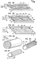
- Figs. 32 - 37 represent electric field devices as ion source, wherein a very long transmission line or lines are disposed on a surface of a fine ceramic dielectric body as linear corona discharge electrode, one end of said transmission line being provided with an input terminal for apply a voltage.
- This structure of discharge electrode is especially appropriate for using a very short-time pulse high voltage of about 1 ns - 1000 ns in pulse length as impressed voltage.
- a pulse voltage runs from input end as progressive wave with generating intense pulse corona discharge, and plasma is formed.
- a discharge caused by pulse high voltage having such a steep rise has an especially active discharge-chemical action, and is suitable to be utilized in an ozonizer or in oxidation of No x , SO or the like.
- corona transmission line two parallel long transmission lines 176, 177 of narrow strip form as linear corona discharge electrode (hereinafter, referred to as "corona transmission line") are disposed to meander on a rectangular fine ceramic dielectric plate 1, in accordance with the method of invention.
- the aforementioned very short-time pulse high voltage from a very short-time pulse high voltage source 180 is impressed on the device via its input terminals 178, 179.
- the impressed voltage propagates along transmission lines 176 - 177 to the ends 181, 182.
- an active plasma as mentioned above is generated between transmission lines 176 and 177.
- the ends 181, 182 are open as shown on the drawings, a progressive wave voltage is reflected.
- a resistance equal to surge impedance of transmission lines is inserted between both ends, the reflection will be eliminated.
- Fig. 33 represents a modification of the device in Fig. 32, in which electrodes 176, 177 are disposed in interdigitated relation, as shown on the drawing.
- the progressive wave travels as shown by arrows 183 - 184 - 185 ... to the end 186.
- Fig. 34 shows an electric field device produced by technique depicted by Figs. 1 wherein a planar induction electrode 9 is embedded within a rectangular fine ceramic dielectric plate l8, and along linear corona discharge electrode 187 of strip form is arranged on a surface 2 of dielectric plate 18 to meander, so that parts of the line may be parallel to each other and equidistant, whereby electrode 187 and planar induction electrode 9 beneath it form transmission lines via dielectric layer.
- a progressive wave high voltage runs as shown by arrows 188 - 189 - 190 ... to the end 191. While the voltage wave proceeds, a creeping corona discharge is generated along surface 2 of dielectric body from the corona discharge electrode 187 of narrow strip form to both sides thereof and an active plasma as referred to above appears.
- Fig. 35 shows a cylindrical electric field device 192 which has been constructed by bending an electric field device of Fig. 34 about a lengthwise directed axis, so that the upper surface may come inside.
- Fig. 36 shows a similar cylindrical electric field device 193 which has been constructed bending the same, so that the upper surface may come outside. In these devices, an active corona is generated along the inner or outer surface, respectively.
- Fig. 37 illustrates.a modification of electric field device in Fig. 36 wherein a long linear corona discharge electrode is arranged to form helix on the surface of a fine ceramic cylinder 193.
- Transmission lines are formed by a cylindrical induction electrode embedded within cylinder 193 and the helical corona discharge electrode 194.
- a very short-time pulse high voltage is applied between two said transmission lines by way of terminals 178, 179, a progressive wave travels with depicting a helix along electrode 194, and active coronas are generated on right and left sides of electrode.
- the electrode 194 is printed on the outer surfnce of green cylinder which has been shaped from a green sheet.
- Fig. 38 illustrates an apparatus in which electric field devices according to this invention are employed as ion source.
- the apparatus can be utilized for oxidizing SOx, NOx etc. in waste combustion gases from motorcar engine, boiler etc., or for generating ozone.
- a number of electric field devices e.g. shown in Fig. lE, Fig. 1F, Fig. 17A, Fig. 17B, Fig. 32, Fig. 33 and Fig. 34, especially electric field devices 195 of Fig. 34 having long corona discharge electrodes 187 of narrow strip form on both surfaces of a fine ceramic dielectric plate 18, are arranged parallel to the gas current in a gas duct 196.
- a very short-time pulse high voltage is applied between corona discharge electrode 187 of narrow strip form and embedded planar induction electrode -9 of each electric field device 195 from a very short-time pulse high voltage source 180 by way of terminals 178, 179.
- active plasma is generated on both sides of all electric field devices 195.
- a waste combustion gas containing noxious componants such as SOx and NO x is passed through the duct 196 from inlet on this side in the direction of arrow 197, these components are oxidized due to discharge-chemical action of said plasma to form S0 3 an 1 N0 2 , which are easily removed by wet process.
- each planar induction electrode 9 embedded in fine ceramic plate should be formed hollow and air or water should be passed through the interior of electrode to cool each electric field device 195.
- any of electric field devices having cylindrical shape or any other shape according to this invention such as those illustrated in Fig. 3, Fig. 5, Fig. 5, Fig. 6, Fig. 35, Fig. 36, and Fig. 37, can be effectively disposed in the gas duct 196 in place of an electric field device 195 of plate shape.
- Fig. 39 illustrates an example of application wherein a number of, electric field devices according to this invention, as ion source, are disposed in a fluidized bed 199 of a powder of a material having high resistivity for preventing intense electrification of particles due to fluidization and adhesion of particles to wall.
- reference numeral 198 designates a fluidized bed vessel in which slits for gas flow, e.g. perforated plate 200, are laid in the lower part. A gas from a gas inlet 201 is forced to pass through said perforated plate 200 and fluidizes a powder of a material having high resistivity in the space 202 above said plate to form a fludized bed 199.
- Reference numerals 203, 203a designate electric field devices of Figs. 1 as ion source, which are disposed along - the inner walls of vessel 198.
- Reference numerals 204, 204a ... designate electric field devices 27 of Fig. 7A having corona discharge electrodes of strip form on both sides as ion source, which have been installed vertically, equispaced, and parallel to one another in the space 202.
- A.C. high voltage from an A.C. high voltage source 19 between the corona discharge electrode and the embedded planar electrode of each of all above-mentioned electric field devices plasma is formed on external surfaces of the devices.
- the charge of powder which has been caused by fluidization in the space 202 is removed by virtue of formed plasma, and adhesion of particles to inner walls of vessel 198 by electric force as well as any coagulation of powder itself is effectively prevented.
- Figs. 40 and 41 illustrate examples of application wherein an electric field device of this invention is used as ion source in an electrostatic precipitator. Although all ion source electric field devices mentioned above can be employed for the purpose, the device shown by Fig. 34 is used in these examples.
- Fig. 40 represents a single-stage electrostatic precipitator from which a duct for gas passage is removed.
- Reference numerals 205, 206 denote grounded plate form dust collecting electrodes.
- Reference numeral 207 denotes an ion source electric field device illustrated in Fig. 34 which has a long corona discharge electrode 187 of strip form on both surfaces of a fine ceramic dielectric plate 18.
- a planar induction electrode 9 embedded within body and a corona discharge electrode 187 are equal in D.C. potential because of both electrodes being connected to a high resistance 208 by way of terminals 179, 178.
- a negntive D.C. high voltage is applied to planar induction electrode 9 and corona discharge electrode 187 by connecting the terminal 178 to a negative D.C.
- Reference numeral 180 denotes a pulse high voltage source which applies a pulse high voltage between terminals 178 and 179 by way of coupling condensers 211, 213, and thereby causes corona discharge electrode 187 to generate creeping pulse corona discharge along surfaces on both sides of ceramic dielectric body 18.
- a planar plasma ion source is formed. Negative ions are removed from this plasma ion source under the action of a D.C. electric field formed in dust-collecting spaces 213, 214 between corona discharge electrode 187 and dust collecting electrodes 205, 206, and flow toward dust collecting electrodes 205, 206.
- Fig. 41 shows a two-stage electrostatic precipitator from which a duct for gas passage is removed.
- Reference numeral 217 denotes a charging section having a structure similar to that shown in Fig. 40, but the size in the direction of gas flow being short. In this charging section, dust particles of a dust laiden gas flowing in the direction of arrow 215 are negatively charged.
- Reference numeral 218 denotes a collecting section comprising a group of parallel planar electrodes 219, 220, 221, 222, 223 .... Every other electrode 219, 221, ... is grounded. The remianing intermediates electrodes 220, 222 ... are insulated and a negative D.C. high voltage is applied to them by a D.C. high voltage source 224.
- a planar ion source as ion source, can be formed by virtue of utilizing an electric field device of fine ceramic body according to this invention.
- the charging efficiency and the dust-collecting efficiency resulting therefrom can be remarkably increased, as compared with the case when a prior corona discharge electrode of strip form is used.
- Various electric field devices can be provided with a number of small holes penetrating through the device and thereby permit to feed air, a gas or a liquid from back side to front through said small holes.
- the adhesion of a powder to the surface can be prevented and any electromechanical effects for handling a powder, such as repelling, floating and transporting, are enhanced.
- the small holes can be utilized as inlet for an object gas.
- an electric discharge is caused within small hole to obtain a special effect.
- an inert gas is fed to an electric discharge area through small holes to prevent ignition and explosion due to discharge.
- Figs. 42 show an example of above-mentioned perforation applied to the electric field device shown in Figs. lA - IF.
- Fig. 42A is a perspective view of a perforated electric field device, partly showing a section.
- Fig. 42B is a detail drawing of a part about a small hole.
- An electric field device shown in Fig. 42A has a large number of equidistant small holes 226 in the areas between strip-shaped corona discharge electrodes 3 and 4, 4 and 5 ....
- corona discharge electrodes are printed on the upper surface of upper layer green sheet 1 as mentioned in the explanation of Figs. lA - IF.
- an induction electrode 9 should have a vacent circle around a small hole 226, the diameter of said circle being larger than that of small hole, in order to prevent exposing of induction electrode 9 to the small hole. Thereby, an occurrence of spark between induction electrode 9 and electrode 3, 4 or 5 can be inhibited.
- Fig. 43 represents an air slide conveyor composed of three-phase contact type electric field curtain devices of one-phase-exposed type, as shown'in Fig. 16, which are provided with a number of small holes.
- reference numeral 69 denotes a three-phase contact type electric field curtain device of one-phase-exposed type.
- Reference numeral 226 designates many small holes disposed in every space between electrodes of electric field device 69.
- Air is spouted through said small holes 226 toward above the device when air is forced to flow through an inlet 230 to an air chamber 229 arranged beneath small holes 226.
- electric field curtain devices 69 are arranged on the underside of flume 231 and a powder is made to fall from an inlet 232 located on the left side above, the powder immediately contacts with the upper surface of electric field curtain device 69 to charge and is repelled.
- the repelled particles of powder float under the combined actions of said progressive wave non-uniform electric field and said spouted air, are conveyed in the direction of arrow 228, and are expelled out from an outlet 223. In this case, floating and conveying are widely enhanced by the action of spouting air.
- Fig. 44 shows a modification of device shown in Fig. 42, wherein a number of slits are provided in place of small holes.
- This electric field device 234 is composed of many modules 235 arranged parallel and equidistant.
- This module 235 comprises a rectangular fine ceramic dielectric body 236 having rectangular cross section. Said dielectric body has an induction electrode 237 embedded in itself, and filmy electrodes 238, 239 on both sides. The sharp upper edges 240, 241 of said filmy electrodes constitutes corona discharge electrodes.
- an A.C. high voltage is applied between the electrodes 238, 239 and an embedded induction electrode 237 from an A.C.
- the device 234 has a function quite similar to that of device in Figs. 42.
- Fig. 45A represents another example of structure of perforated electric field device, which has a planar electrode 245 on the upper surface of a fine ceramic dielectric body plate 244 and further another planar electrode 246 embedded in the body.
- a number of small holes 266 penetrates through these planar electrodes 245, 246 and the fine ceramic dielectric body plate 244.
- inner peripheral parts 247, 248 of electrodes 245, 246 are exposed to the interior of small holes 226, as shown by Fig. 45B.
- a very short-time pulse high voltage from a very short-time pulse high voltage source 180 is applied between both electrodes, a creeping corona discharge is generated along the inner wall surface of small hole 226 between inner peripheral parts 247 and 248.
- This corona discharge acts as plasma ion source to feed ions on the upper surface of the dielectric body plate 244. If air or a gas is passed upward through small holes 226 from below, various aforementioned effects are obtained.
- Fig. 46 shows a modification of the device shown in Fig. 45, in which the fine ceramic dielectric body 244 has a planar electrode 245a also on the lower surface thereof.
- the discharge along the inner surface of small hole 226 is directed upward and downward from peripheral part 248. Therefore, when a gas is fed through small holes 226, a discharge-chemical action is doubled, as compared with that in the device of Fig. 45. On the other hand, when a charged liquid is passed through small holes 226, the electric charge is effectively removed.
- Fig. 47 represents a modification of the device shown by Fig. 46 wherein a very short-time pulse high voltage from a very short-time pulse high voltage source 180 is applied between an upper planar electrode 245 and an inner embedded planar electrode 246 by way of terminals 15, 16 to generate plasma in the upper half of every small hole 226, and additionally a D.C. high voltage from a D.C. high voltage source 249 is applied between electrode 246 and lower planar electrode 245a via terminals 16, 250, thereby a monopolar ion supply source is constituted, which feeds downward selectively negative ions in the case of wiring shown in Fig. 47.
- This device is employable for supplying charges of required polarity, i.e. negative or positive, uniformly on the surface of photosensitive material having photoconductivity for an electronic photography. When this is a case, the intensity of current can be modified as desired by changing the voltage of the D.C. voltage source 249.
- Fig. 48 shows an apparatus using a modification of the device in Fig. 47 wherein separnte annular discharge electrodes 251, 252, 253 ... are disposed around respective small holes so that the inner peripheral part of electrode may be exposed to the interior of small hole, in place of the upper planar electrode 245.
- a signal pulse high voltage from a pulse source 257 is applied between the embedded planar electrode 246 and each of said annular electrodes by way of terminal 16 and terminals 254, 255, 256 ... to generate a plasma in the upper half of each small hole, monopolar ions of prescribed polarity (in this embodiment, negative) are attracted downward under the action of a D.C.
- an electrostatic latent image of a letter (or a pattern) consisting of dots can be formed on the surface 259 by giving pulse signals corresponding to said letter to terminals 254, 255, 256 .... After a toner is electrostatically displaced thereto, the image is transferred on a paper and fixed to form an electronic photograph.
- Fig. 49 shows a structure of an electric field attaching apparatus, or electrostatic chuck for attaching and fixing paper, plastic sheet, machine part etc., wherein an electric field device illustrated in Figs. lA - IF is used.
- Reference numernl 18 in the drawing denotes a fine ceramic dielectric plate having a slight electric conductivity. Electrodes 3, 4, 5 ... of strip form are disposed on the surface of the plate and a planar induction electrode 9 is embedded in said fine ceramic dielectric plate.
- a D.C. voltage is applied thereto from a D.C. electric source 30 via a switch 260.
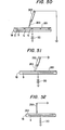
- Fig. 50 shows one example of application of electric field attaching apparatus 18 shown in Fig. 49.
- On said attaching apparatus is attached a sheet of paper or a plastic sheet material 261 to fix.
- a picture or letters are written on the plastic sheet material 261 by means of a magnetic brush 263 which has been formed by attracting an iron power having adhered coloring toner particles with a grounded magnet 262
- coloring toner particles attached to iron powder by charging due to contact are transferred onto the sheet material 261 under the attracting action of the planar electrode 9.
- the picture or letters on the sheet material 216 are fixed.
- FIG. 51 shows a modified apparatus as mentioned above.
- Fig. 52 when a picture or letters are written on a sheet material 261 with a grounded metal pen, negative charge passes from the metal pen onto the sheet material 261 and an electrostatic latent image corresponding to said picture or letters is formed. After releasing the sheet material from the device 18, the surface of sheet material is swept with a magnetic brush including toner. As a result, the toner is transferred onto the electrostatic latent image to develop. When heated, a fixed picture or fixed letters are formed on sheet material 261.
- the operation of the device composed of fine ceramic according to this invention is frequently accompanied by heating.
- a viscous liquid is conveyed through the device for conveying liquid shown in Fig. 22
- viscosity of the liquid lowers by heating a cylindrical three-phase contact type electric field curtain device 96, and conveying will be performed without difficulties.
- separate currents for heating may be supplied to electrodes for forming electric field from a different D.C. or A.C. electric source, or electromagnetic induction may be utilized. Heat is generated in electrodes due to Joule heat. This is also an important feature of this invention.
- the cylindrical electric field device 96 which is the same as that of Fig. 19 may be surrounded by a coil.
- a high-frequency A.C. current flows through said coil, different high-frequency A.C. currents flow in annular electrodes 97, 98, 99, 97a, 98b, 99c ..., to perform easily heating.
Landscapes
- Physics & Mathematics (AREA)
- Engineering & Computer Science (AREA)
- Plasma & Fusion (AREA)
- General Physics & Mathematics (AREA)
- Textile Engineering (AREA)
- Physical Or Chemical Processes And Apparatus (AREA)
- Electrostatic Separation (AREA)
- Elimination Of Static Electricity (AREA)
- Dot-Matrix Printers And Others (AREA)
- Printers Or Recording Devices Using Electromagnetic And Radiation Means (AREA)
- Compositions Of Oxide Ceramics (AREA)
Applications Claiming Priority (2)
| Application Number | Priority Date | Filing Date | Title |
|---|---|---|---|
| JP155618/82 | 1982-09-07 | ||
| JP57155618A JPS5944797A (ja) | 1982-09-07 | 1982-09-07 | 物体の静電的処理装置 |
Publications (3)
| Publication Number | Publication Date |
|---|---|
| EP0102569A2 true EP0102569A2 (de) | 1984-03-14 |
| EP0102569A3 EP0102569A3 (en) | 1984-10-10 |
| EP0102569B1 EP0102569B1 (de) | 1989-11-23 |
Family
ID=15609942
Family Applications (1)
| Application Number | Title | Priority Date | Filing Date |
|---|---|---|---|
| EP83108152A Expired EP0102569B1 (de) | 1982-09-07 | 1983-08-18 | Vorrichtung für elektrische Korona entladung, Verfahren zu ihrer Herstellung und elektrostatisches Behandlungsgerät mit einer solchen Vorrichtung |
Country Status (5)
| Country | Link |
|---|---|
| US (2) | US4652318A (de) |
| EP (1) | EP0102569B1 (de) |
| JP (1) | JPS5944797A (de) |
| KR (1) | KR920007084B1 (de) |
| DE (1) | DE3380890D1 (de) |
Cited By (16)
| Publication number | Priority date | Publication date | Assignee | Title |
|---|---|---|---|---|
| FR2561829A1 (fr) * | 1984-03-26 | 1985-09-27 | Canon Kk | Procede et dispositif pour charger et decharger electriquement un element |
| FR2561830A1 (fr) * | 1984-03-26 | 1985-09-27 | Canon Kk | Procede et dispositif pour charger et decharger electriquement un element |
| GB2190544A (en) * | 1986-05-06 | 1987-11-18 | British Aerospace | Electrostatically protecting articles from particle bombardment |
| DE3731168A1 (de) * | 1987-09-14 | 1989-03-30 | Sorbios Verfahrenstech | Vorrichtung zur erzeugung von kaltem plasma fuer wechselspannungsanregung im khz-bereich, vorzugsweise zur erzeugung von ozon, und verfahren zur herstellung der vorrichtung |
| EP0287838A3 (en) * | 1987-03-31 | 1990-07-18 | Fujitsu Limited | An apparatus for transporting an electrically conductive wafer |
| US4963738A (en) * | 1986-12-22 | 1990-10-16 | Xerox Corporation | Flat comb-like scorotron charging device |
| EP0392678A3 (de) * | 1989-03-20 | 1991-05-02 | Xerox Corporation | Verfahren und Vorrichtung zum Transport von Ionen in einem Trägergas |
| GB2243725A (en) * | 1990-05-02 | 1991-11-06 | Peng Yu Hshiang | A low thermal shock plate type corona generator |
| US5200670A (en) * | 1989-10-06 | 1993-04-06 | British Aerospace Public Limited Company | Surface discharge plasma cathode electron beam generating assembly |
| DE4241927A1 (de) * | 1992-12-11 | 1994-06-16 | Max Planck Gesellschaft | Zur Anordnung in einem Vakuumgefäß geeignete selbsttragende isolierte Elektrodenanordnung, insbesondere Antennenspule für einen Hochfrequenz-Plasmagenerator |
| US5364600A (en) * | 1990-11-02 | 1994-11-15 | Sorbios Gmbh | Apparatus for producing ozone from oxygen |
| DE19955671A1 (de) * | 1999-11-19 | 2001-05-31 | Muegge Electronic Gmbh | Vorrichtung zur Erzeugung von Plasma |
| DE102005001158A1 (de) * | 2005-01-10 | 2006-07-27 | Fraunhofer-Gesellschaft zur Förderung der angewandten Forschung e.V. | Barrierenentladungselektrode mit Kühlung |
| EP1933605A4 (de) * | 2005-09-16 | 2014-04-30 | Toyo Advanced Tech Co | Plasmaerzeugungseinrichtung und plasmaerzeugungsverfahren |
| CN106861908A (zh) * | 2017-03-03 | 2017-06-20 | 中冶宝钢技术服务有限公司 | 烧结机电除尘器维修工艺 |
| CN109633071A (zh) * | 2019-02-27 | 2019-04-16 | 贵州健安德科技有限公司 | 一种利用uplc-ms/ms法检测水中噻森铜的方法 |
Families Citing this family (85)
| Publication number | Priority date | Publication date | Assignee | Title |
|---|---|---|---|---|
| JPS5944797A (ja) * | 1982-09-07 | 1984-03-13 | 増田 閃一 | 物体の静電的処理装置 |
| US4666679A (en) * | 1984-07-18 | 1987-05-19 | Ngk Spark Plug Co., Ltd. | Ceramic ozonizer |
| US4783716A (en) * | 1986-01-30 | 1988-11-08 | Canon Kabushiki Kaisha | Charging or discharging device |
| US4745520A (en) * | 1986-10-10 | 1988-05-17 | Ransburg Corporation | Power supply |
| US4803593A (en) * | 1986-10-14 | 1989-02-07 | Ricoh Company, Ltd. | Flat solid discharging device |
| US4794254A (en) * | 1987-05-28 | 1988-12-27 | Xerox Corporation | Distributed resistance corona charging device |
| JPH01117240A (ja) * | 1987-10-30 | 1989-05-10 | Masao Iwanaga | 放電素子およびその応用装置 |
| CA1316980C (en) * | 1988-12-27 | 1993-04-27 | Daniel C. Hughey | Power supply |
| US5272414A (en) * | 1990-05-08 | 1993-12-21 | I.T.M. Corporation | Discharge element, method of producing the same and apparatus comprising the same |
| JPH0414784A (ja) * | 1990-05-08 | 1992-01-20 | Masao Iwanaga | 放電素子、その製造方法および応用装置 |
| US5452177A (en) | 1990-06-08 | 1995-09-19 | Varian Associates, Inc. | Electrostatic wafer clamp |
| EP0500937A4 (en) * | 1990-06-28 | 1993-09-15 | Daihen Corporation | Method of electrically joining ceramics, device used therefor and adhesive agent therefor |
| CA2079538C (en) * | 1991-10-14 | 2000-11-21 | Toshiya Watanabe | Method of manufacturing a corona discharge device |
| WO1994011944A1 (en) * | 1992-11-06 | 1994-05-26 | Varian Associates, Inc. | Electrostatic wafer clamp |
| US5384681A (en) * | 1993-03-01 | 1995-01-24 | Toto Ltd. | Electrostatic chuck |
| US6018471A (en) | 1995-02-02 | 2000-01-25 | Integrated Environmental Technologies | Methods and apparatus for treating waste |
| US5798497A (en) * | 1995-02-02 | 1998-08-25 | Battelle Memorial Institute | Tunable, self-powered integrated arc plasma-melter vitrification system for waste treatment and resource recovery |
| US5666891A (en) * | 1995-02-02 | 1997-09-16 | Battelle Memorial Institute | ARC plasma-melter electro conversion system for waste treatment and resource recovery |
| US5847353A (en) * | 1995-02-02 | 1998-12-08 | Integrated Environmental Technologies, Llc | Methods and apparatus for low NOx emissions during the production of electricity from waste treatment systems |
| US5665604A (en) * | 1995-08-18 | 1997-09-09 | The Regents Of The University Of California, Office Of Technology Transfer | Method and apparatus for detecting halogenated hydrocarbons |
| US5858099A (en) | 1996-04-09 | 1999-01-12 | Sarnoff Corporation | Electrostatic chucks and a particle deposition apparatus therefor |
| US6399143B1 (en) * | 1996-04-09 | 2002-06-04 | Delsys Pharmaceutical Corporation | Method for clamping and electrostatically coating a substrate |
| US5788814A (en) * | 1996-04-09 | 1998-08-04 | David Sarnoff Research Center | Chucks and methods for positioning multiple objects on a substrate |
| US6070033A (en) * | 1996-10-07 | 2000-05-30 | Aetas Peripheral Corporation | Charging device for an electrophotographic imaging forming system utilizing thin film conducting members |
| AT1590U1 (de) * | 1996-10-17 | 1997-08-25 | Maitron Gmbh | Elektrodenanordnung |
| JP3801730B2 (ja) | 1997-05-09 | 2006-07-26 | 株式会社半導体エネルギー研究所 | プラズマcvd装置及びそれを用いた薄膜形成方法 |
| US6039816A (en) * | 1997-06-12 | 2000-03-21 | Ngk Spark Plug Co., Ltd. | Ozonizer, water purifier and method of cleaning an ozonizer |
| US6055928A (en) | 1998-03-02 | 2000-05-02 | Ball Semiconductor, Inc. | Plasma immersion ion processor for fabricating semiconductor integrated circuits |
| JP2961103B1 (ja) * | 1998-04-28 | 1999-10-12 | 三菱重工業株式会社 | プラズマ化学蒸着装置 |
| US6149774A (en) | 1998-06-10 | 2000-11-21 | Delsys Pharmaceutical Corporation | AC waveforms biasing for bead manipulating chucks |
| US6063194A (en) | 1998-06-10 | 2000-05-16 | Delsys Pharmaceutical Corporation | Dry powder deposition apparatus |
| US6284205B1 (en) * | 1998-08-21 | 2001-09-04 | Kabushiki Kaisha Toshiba | Ozonizing unit ozone generator and ozone-processing system |
| US6292085B1 (en) * | 1999-04-09 | 2001-09-18 | Electronic Descaling 2000, Inc. | Multiple coil assembly for use with electronic descaling unit |
| US6923979B2 (en) * | 1999-04-27 | 2005-08-02 | Microdose Technologies, Inc. | Method for depositing particles onto a substrate using an alternating electric field |
| DE19931366A1 (de) * | 1999-07-07 | 2001-02-01 | T E M Gmbh | Flache Baugruppe zur elektrischen Erzeugung eines Plasmas in Luft |
| JP3464177B2 (ja) * | 1999-09-06 | 2003-11-05 | 沖電気工業株式会社 | 半導体製造装置および静電気除去方法 |
| DE19960401A1 (de) * | 1999-12-06 | 2001-07-12 | Fzm Fertigungszentrum Maschb G | Elektrode für Plasmaquelle |
| KR20020059438A (ko) * | 1999-12-09 | 2002-07-12 | 보스트 스티븐 엘. | 편평한 막 전극을 갖는 정전 척 |
| US6603650B1 (en) | 1999-12-09 | 2003-08-05 | Saint-Gobain Ceramics And Plastics, Inc. | Electrostatic chuck susceptor and method for fabrication |
| US6723274B1 (en) | 1999-12-09 | 2004-04-20 | Saint-Gobain Ceramics & Plastics, Inc. | High-purity low-resistivity electrostatic chucks |
| DE10027247C2 (de) * | 2000-05-31 | 2003-09-25 | Iut Inst Fuer Umwelttechnologi | Plasmagenerator mit dielektrisch behinderter Entladung |
| EG23455A (en) * | 2001-08-01 | 2005-09-28 | Sharp Kk | Ion generator and electric apparatus and their uses in an air condition. |
| US6897615B2 (en) * | 2001-11-01 | 2005-05-24 | Axcelis Technologies, Inc. | Plasma process and apparatus |
| FR2836157B1 (fr) * | 2002-02-19 | 2004-04-09 | Usinor | Procede de nettoyage de la surface d'un materiau enduit d'une susbstance organique, generateur et dispositif de mise en oeuvre |
| US20050044619A1 (en) * | 2002-08-02 | 2005-03-03 | Mattson Roy W. | Sanitation suction device |
| US20040066601A1 (en) * | 2002-10-04 | 2004-04-08 | Varian Semiconductor Equipment Associates, Inc. | Electrode configuration for retaining cooling gas on electrostatic wafer clamp |
| CN101621181B (zh) * | 2003-05-15 | 2012-09-12 | 夏普株式会社 | 离子发生元件、离子发生装置、电气设备 |
| US7543546B2 (en) * | 2003-05-27 | 2009-06-09 | Matsushita Electric Works, Ltd. | Plasma processing apparatus, method for producing reaction vessel for plasma generation, and plasma processing method |
| US7589296B2 (en) | 2003-09-12 | 2009-09-15 | Ngk Insulators, Ltd. | Plasma generating electrode and plasma reactor |
| JP4684222B2 (ja) * | 2004-03-19 | 2011-05-18 | 株式会社クリエイティブ テクノロジー | 双極型静電チャック |
| DE102004060377A1 (de) * | 2004-12-15 | 2006-06-29 | MAX-PLANCK-Gesellschaft zur Förderung der Wissenschaften e.V. | Verfahren und Vorrichtung zum Betrieb einer Plasmaeinrichtung |
| JP4608630B2 (ja) * | 2005-02-21 | 2011-01-12 | 独立行政法人産業技術総合研究所 | イオン発生器及び除電器 |
| JP2006302625A (ja) * | 2005-04-19 | 2006-11-02 | Matsushita Electric Works Ltd | プラズマ処理装置及びプラズマ処理方法 |
| US7529075B1 (en) * | 2005-08-23 | 2009-05-05 | The United States Of America As Represented By The Secretary Of The Army | Systems and methods involving electric-field cages |
| JP2007234437A (ja) * | 2006-03-02 | 2007-09-13 | Trinc:Kk | プラズマ放電式除電器 |
| JP2008205209A (ja) * | 2007-02-20 | 2008-09-04 | Matsushita Electric Works Ltd | プラズマ処理装置 |
| US8084757B2 (en) * | 2008-01-17 | 2011-12-27 | Applied Materials, Inc. | Contamination prevention in extreme ultraviolet lithography |
| DE102008007219B4 (de) * | 2008-02-01 | 2010-02-18 | Fraunhofer-Gesellschaft zur Förderung der angewandten Forschung e.V. | Verfahren und Fluidisierbehälter zur Verbesserung der Aufladung von Pulverpartikeln mittels neuer gepulster Hochspannungstechnik |
| JP5223424B2 (ja) * | 2008-04-08 | 2013-06-26 | パナソニック株式会社 | 集塵装置 |
| JP5078792B2 (ja) * | 2008-07-29 | 2012-11-21 | 京セラ株式会社 | 誘電性構造体、誘電性構造体を用いた放電装置、流体改質装置、および反応システム |
| EP2180768A1 (de) * | 2008-10-23 | 2010-04-28 | TNO Nederlandse Organisatie voor Toegepast Wetenschappelijk Onderzoek | Vorrichtung und Verfahren zur Behandlung eines Objekts |
| US20110233067A1 (en) * | 2009-09-25 | 2011-09-29 | Conyers Technology Group, Llc | Electrochemical processing of fluids |
| GB0919274D0 (en) * | 2009-11-03 | 2009-12-16 | Univ The Glasgow | Plasma generation apparatus and use of plasma generation apparatus |
| JP5491632B2 (ja) * | 2010-08-18 | 2014-05-14 | 京セラ株式会社 | イオン風発生体及びイオン風発生装置 |
| JP5626899B2 (ja) * | 2011-05-17 | 2014-11-19 | 株式会社日立製作所 | 大気圧プラズマ処理装置 |
| DE102011076806A1 (de) | 2011-05-31 | 2012-12-06 | Leibniz-Institut für Plasmaforschung und Technologie e.V. | Vorrichtung und Verfahren zur Erzeugung eines kalten, homogenen Plasmas unter Atmosphärendruckbedingungen |
| DE102011105713B4 (de) * | 2011-06-23 | 2014-06-05 | Cinogy Gmbh | Elektrodenanordnung für eine dielektrisch behinderte Gasentladung |
| KR102076660B1 (ko) * | 2012-06-21 | 2020-02-12 | 엘지전자 주식회사 | 공기 조화기 및 그 제어방법 |
| WO2014085720A1 (en) | 2012-11-27 | 2014-06-05 | Clearsign Combustion Corporation | Multijet burner with charge interaction |
| US20140170575A1 (en) * | 2012-12-14 | 2014-06-19 | Clearsign Combustion Corporation | Ionizer for a combustion system, including foam electrode structure |
| JP5983529B2 (ja) * | 2013-05-16 | 2016-08-31 | 株式会社村田製作所 | 放電素子 |
| WO2016205719A1 (en) * | 2015-06-19 | 2016-12-22 | Applied Materials, Inc. | Additive manufacturing with electrostatic compaction |
| CN107708970A (zh) * | 2015-06-19 | 2018-02-16 | 应用材料公司 | 增材制造中的选择性粉末沉积 |
| CN106076625B (zh) * | 2016-08-11 | 2017-06-16 | 天津大学 | 一种圆筒形微静电过滤器 |
| US10619845B2 (en) * | 2016-08-18 | 2020-04-14 | Clearsign Combustion Corporation | Cooled ceramic electrode supports |
| US10322890B2 (en) * | 2016-10-17 | 2019-06-18 | Oakland University | Sheet metal blank destacker |
| KR102741869B1 (ko) | 2017-09-11 | 2024-12-11 | 더 리서치 파운데이션 포 더 스테이트 유니버시티 오브 뉴욕 | 전기역학적 차폐를 이용한 태양 전지판 자가 세정 시스템 및 방법 |
| CN108993773B (zh) * | 2018-08-07 | 2023-11-17 | 中国船舶重工集团公司第七一八研究所 | 一种印刷线板式放电电极 |
| JP2020034180A (ja) * | 2018-08-27 | 2020-03-05 | 国立大学法人埼玉大学 | 交流電界による有害性排ガス処理装置の燃焼炉 |
| WO2020084594A1 (en) | 2018-10-25 | 2020-04-30 | National Research Council Of Canada | Printed film electrostatic concentrator for radon detection |
| EP3668280A1 (de) * | 2018-12-14 | 2020-06-17 | ABB Schweiz AG | Länglicher nichtthermischer plasmareaktor zur optimalen kopplung mit gepulster stromversorgung |
| US11040353B1 (en) * | 2020-08-12 | 2021-06-22 | James T. Cash | Electrostatic air filter used to destroy pathogens and viruses with infrared heat |
| DE102022130811A1 (de) * | 2022-11-22 | 2024-05-23 | Schiedel Gmbh | Abgasrohr, Abgasreinigungsgerät, Verfahren zur Reinigung eines Abgasrohrs sowie Verwendung eines Abgasrohrs |
| US20240253125A1 (en) * | 2023-01-31 | 2024-08-01 | Lawrence Livermore National Security, Llc | Electrostatic powder remover for powder bed fusion additive manufacturing |
| CN120568558A (zh) * | 2024-02-29 | 2025-08-29 | 北京北方华创微电子装备有限公司 | 静电消除装置及半导体工艺设备 |
Family Cites Families (43)
| Publication number | Priority date | Publication date | Assignee | Title |
|---|---|---|---|---|
| US3004197A (en) * | 1956-12-13 | 1961-10-10 | Aerovox Corp | Ceramic capacitor and method of making it |
| US3470905A (en) * | 1965-04-09 | 1969-10-07 | Don Edward Heskett | Pressure responsive device for controlling liquid level in tanks |
| US3615980A (en) * | 1970-02-12 | 1971-10-26 | Daniel J Rose | Decal metallization of ceramic substrates |
| GB1381783A (en) * | 1971-05-12 | 1975-01-29 | Masuda S | Apparatus for controlling the movement of light particles |
| BE789321A (fr) * | 1971-09-29 | 1973-01-15 | Masuda Senichi | Procede pour l'application au moyen d'un rideau de champs electriques de revetements formes par des particules de poussieres etdispositif pourla mise en oeuvre du procede |
| BE789579A (fr) * | 1971-10-06 | 1973-02-01 | Masuda Senichi | Enceinte pour l'application, au moyen d'un rideau de champs electriquesdu type contact, de revetements formes par des poudres chargees electrostatiquement |
| JPS5347684B2 (de) * | 1972-06-26 | 1978-12-22 | ||
| US3882059A (en) * | 1973-05-11 | 1975-05-06 | Technical Ceramics Inc | Method of making ceramic capacitor |
| US3970905A (en) * | 1974-07-10 | 1976-07-20 | Onoda Cement Company, Ltd. | Thin wire type of electric field curtain system |
| CA1007737A (en) * | 1974-09-17 | 1977-03-29 | Northern Electric Company | Semiconductor optical modulator |
| FR2296958A1 (fr) * | 1975-01-06 | 1976-07-30 | Cellophane Sa | Nouvelles electrodes d'ionisation |
| JPS51103328A (en) * | 1975-03-07 | 1976-09-11 | Nippon Denso Co | Gasunenshosochino seigyosochi |
| US3968405A (en) * | 1975-04-14 | 1976-07-06 | Testone Anthony Quintin | Static electricity suppressor with patterned coating and method of making |
| GB1549055A (en) * | 1975-04-30 | 1979-08-01 | Sumitomo Precision Prod Co | Ozone generator |
| JPS52106400A (en) * | 1976-03-04 | 1977-09-06 | Mizusawa Industrial Chem | Process for producing alkali aluminosilicate having excellent whiteness from clay ore containing iron ingredient |
| JPS5922358B2 (ja) * | 1976-03-08 | 1984-05-25 | 太平洋セメント株式会社 | 安全型電界カ−テン装置 |
| SE7704663L (sv) * | 1976-04-26 | 1977-10-27 | Izon Corp | Ljusforsterkningsanordning |
| JPS5833465B2 (ja) * | 1976-05-31 | 1983-07-20 | 松下電工株式会社 | 太陽熱給湯蓄熱装置 |
| US4155093A (en) * | 1977-08-12 | 1979-05-15 | Dennison Manufacturing Company | Method and apparatus for generating charged particles |
| GB2012493B (en) * | 1977-09-05 | 1982-02-24 | Masuda S | Device for electrically charging particles |
| JPS5442017A (en) * | 1977-09-07 | 1979-04-03 | Mitsubishi Heavy Ind Ltd | Menbrane layout of low temperature tank |
| JPS5473106A (en) * | 1977-11-20 | 1979-06-12 | Meinan Machinery Works | Jointing and reinforcing veneer |
| JPS5481125A (en) * | 1977-12-12 | 1979-06-28 | Nippon Steel Corp | Ingot making by oneedirectional solidification |
| JPS5483218A (en) * | 1977-12-14 | 1979-07-03 | Hitachi Ltd | Method of controlling legs of superconductively magnetically floating vehicle |
| US4325763A (en) * | 1978-04-25 | 1982-04-20 | Nippon Electric Company, Ltd. | Method of manufacturing ceramic capacitors |
| JPS54151035A (en) * | 1978-05-18 | 1979-11-27 | Fujitsu Ltd | Recording head |
| JPS5547574A (en) * | 1978-09-28 | 1980-04-04 | Sumitomo Electric Ind Ltd | Optical character reading device |
| JPS5583218A (en) * | 1978-12-19 | 1980-06-23 | Matsushita Electric Industrial Co Ltd | Method of fabricating spiral ceramic capacitor |
| JPS55113581A (en) * | 1979-02-26 | 1980-09-02 | Canon Inc | Liquid jet recording method |
| JPS55154383A (en) * | 1979-05-12 | 1980-12-01 | Tokyo Shibaura Electric Co | Alumina and alumina metallizing method |
| US4265641A (en) * | 1979-05-18 | 1981-05-05 | Monsanto Company | Method and apparatus for particle charging and particle collecting |
| ES491478A0 (es) * | 1979-05-18 | 1981-06-01 | Monsanto Co | Un aparato para cargar particulas de tamano inferior a la micra y mayores en una corriente de gas. |
| JPS5648666A (en) * | 1979-09-28 | 1981-05-01 | Ricoh Co Ltd | Plural sheet recording system |
| JPS56155419A (en) * | 1980-04-30 | 1981-12-01 | Matsushita Electric Works Ltd | Control circuit for loaded alternating current |
| JPS576385A (en) * | 1980-06-12 | 1982-01-13 | Citizen Watch Co Ltd | Movement structure of digital watch |
| JPS5781779A (en) * | 1980-11-11 | 1982-05-21 | Nec Corp | Method for compacting information of facsimile |
| JPS57129856A (en) * | 1981-02-05 | 1982-08-12 | Asahi Chemical Ind | Imcombustible lightweight heat-insulating material |
| JPS57184296A (en) * | 1981-05-09 | 1982-11-12 | Hitachi Ltd | Ceramic circuit board |
| JPS57205757A (en) * | 1981-06-15 | 1982-12-16 | Fuji Xerox Co Ltd | Electrostatic charger |
| JPS57132134A (en) * | 1981-12-29 | 1982-08-16 | Canon Inc | Data copying illuminator |
| JPS58154293A (ja) * | 1982-03-10 | 1983-09-13 | 株式会社日立製作所 | グリ−ンシ−トの寸法安定化法 |
| JPS5944797A (ja) * | 1982-09-07 | 1984-03-13 | 増田 閃一 | 物体の静電的処理装置 |
| JP2919369B2 (ja) * | 1996-07-30 | 1999-07-12 | 鹿児島日本電気株式会社 | 液晶表示装置及びその製造方法 |
-
1982
- 1982-09-07 JP JP57155618A patent/JPS5944797A/ja active Granted
-
1983
- 1983-08-18 DE DE8383108152T patent/DE3380890D1/de not_active Expired
- 1983-08-18 EP EP83108152A patent/EP0102569B1/de not_active Expired
- 1983-09-07 KR KR1019830004207A patent/KR920007084B1/ko not_active Expired
-
1985
- 1985-01-31 US US06/697,063 patent/US4652318A/en not_active Expired - Lifetime
-
1988
- 1988-01-03 US US07/293,757 patent/US4922099A/en not_active Expired - Lifetime
Cited By (21)
| Publication number | Priority date | Publication date | Assignee | Title |
|---|---|---|---|---|
| FR2561830A1 (fr) * | 1984-03-26 | 1985-09-27 | Canon Kk | Procede et dispositif pour charger et decharger electriquement un element |
| USRE33633E (en) * | 1984-03-26 | 1991-07-09 | Canon Kabushiki Kaisha | Method and device for charging or discharging a member |
| FR2561829A1 (fr) * | 1984-03-26 | 1985-09-27 | Canon Kk | Procede et dispositif pour charger et decharger electriquement un element |
| GB2190544A (en) * | 1986-05-06 | 1987-11-18 | British Aerospace | Electrostatically protecting articles from particle bombardment |
| US4963738A (en) * | 1986-12-22 | 1990-10-16 | Xerox Corporation | Flat comb-like scorotron charging device |
| EP0287838A3 (en) * | 1987-03-31 | 1990-07-18 | Fujitsu Limited | An apparatus for transporting an electrically conductive wafer |
| DE3731168A1 (de) * | 1987-09-14 | 1989-03-30 | Sorbios Verfahrenstech | Vorrichtung zur erzeugung von kaltem plasma fuer wechselspannungsanregung im khz-bereich, vorzugsweise zur erzeugung von ozon, und verfahren zur herstellung der vorrichtung |
| EP0392678A3 (de) * | 1989-03-20 | 1991-05-02 | Xerox Corporation | Verfahren und Vorrichtung zum Transport von Ionen in einem Trägergas |
| US5200670A (en) * | 1989-10-06 | 1993-04-06 | British Aerospace Public Limited Company | Surface discharge plasma cathode electron beam generating assembly |
| GB2243725A (en) * | 1990-05-02 | 1991-11-06 | Peng Yu Hshiang | A low thermal shock plate type corona generator |
| US5364600A (en) * | 1990-11-02 | 1994-11-15 | Sorbios Gmbh | Apparatus for producing ozone from oxygen |
| DE4241927A1 (de) * | 1992-12-11 | 1994-06-16 | Max Planck Gesellschaft | Zur Anordnung in einem Vakuumgefäß geeignete selbsttragende isolierte Elektrodenanordnung, insbesondere Antennenspule für einen Hochfrequenz-Plasmagenerator |
| US5434353A (en) * | 1992-12-11 | 1995-07-18 | Max-Planck-Gesellschaft Zur Foerderung Der Wissenschaften E.V. Berlin | Self-supporting insulated conductor arrangement suitable for arrangement in a vacuum container |
| DE19955671A1 (de) * | 1999-11-19 | 2001-05-31 | Muegge Electronic Gmbh | Vorrichtung zur Erzeugung von Plasma |
| DE19955671B4 (de) * | 1999-11-19 | 2004-07-22 | Muegge Electronic Gmbh | Vorrichtung zur Erzeugung von Plasma |
| DE102005001158A1 (de) * | 2005-01-10 | 2006-07-27 | Fraunhofer-Gesellschaft zur Förderung der angewandten Forschung e.V. | Barrierenentladungselektrode mit Kühlung |
| DE102005001158B4 (de) * | 2005-01-10 | 2016-11-10 | Fraunhofer-Gesellschaft zur Förderung der angewandten Forschung e.V. | Barrierenentladungselektroden mit Kühlung und Vorrichtung mit einer solchen Barrierenentladungselektrode |
| EP1933605A4 (de) * | 2005-09-16 | 2014-04-30 | Toyo Advanced Tech Co | Plasmaerzeugungseinrichtung und plasmaerzeugungsverfahren |
| CN106861908A (zh) * | 2017-03-03 | 2017-06-20 | 中冶宝钢技术服务有限公司 | 烧结机电除尘器维修工艺 |
| CN109633071A (zh) * | 2019-02-27 | 2019-04-16 | 贵州健安德科技有限公司 | 一种利用uplc-ms/ms法检测水中噻森铜的方法 |
| CN109633071B (zh) * | 2019-02-27 | 2021-05-07 | 贵州健安德科技有限公司 | 一种利用uplc-ms/ms法检测水中噻森铜的方法 |
Also Published As
| Publication number | Publication date |
|---|---|
| US4652318A (en) | 1987-03-24 |
| JPH0349198B2 (de) | 1991-07-26 |
| US4922099A (en) | 1990-05-01 |
| DE3380890D1 (en) | 1989-12-28 |
| KR920007084B1 (ko) | 1992-08-24 |
| EP0102569A3 (en) | 1984-10-10 |
| JPS5944797A (ja) | 1984-03-13 |
| KR840006448A (ko) | 1984-11-30 |
| EP0102569B1 (de) | 1989-11-23 |
Similar Documents
| Publication | Publication Date | Title |
|---|---|---|
| US4652318A (en) | Method of making an electric field device | |
| US4259707A (en) | System for charging particles entrained in a gas stream | |
| CA1056901A (en) | Method and apparatus for separating dispersed matter from a fluid medium | |
| US4940894A (en) | Electrode for a corona discharge apparatus | |
| AU707667B2 (en) | Apparatus for coating substrates with inductively charged resinous powder particles | |
| CN1038886A (zh) | 印刷装置及其墨粉/显影剂传送系统 | |
| EP0789632B1 (de) | Verfahren zum verbessern der elektrostatischen ladung auf pulvern | |
| JPS60108B2 (ja) | 放電塗装装置 | |
| JPH02210798A (ja) | 物体の静電的処理装置 | |
| US4084019A (en) | Electrostatic coating grid and method | |
| US4988208A (en) | Method of and apparatus for mixing or dispersing particles | |
| US3841264A (en) | Apparatus for applying dust particles by contact type electric field curtain | |
| JPS5944782A (ja) | 沿面コロナ放電素子およびその製造方法 | |
| US7398035B2 (en) | Nanostructure-based solid state charging device | |
| KR0184124B1 (ko) | 다중대전 현상건 | |
| US3865079A (en) | Electrostatic fluid bed powder coating system | |
| US2608176A (en) | Apparatus for electrostatically coating articles | |
| US5385761A (en) | Discharge element, method of producing the same and apparatus comprising the same | |
| US4029995A (en) | Apparatus for producing charged particles | |
| KR920011007B1 (ko) | 전계장치를사용하는물체의정전적처리장치 | |
| Masuda | Industrial applications of electrostatics | |
| US3299809A (en) | Electrostatic printing process for use with printing plate having plural levels | |
| EP0230723A2 (de) | Apparat zum Laden von Pulver und elektrostatischer Pulverbeschichtungsapparat | |
| US5340617A (en) | Electrostatic patterning of multi-layer module lamina | |
| US3433948A (en) | Negative corona discharge system using alternating electric fields across the air gap |
Legal Events
| Date | Code | Title | Description |
|---|---|---|---|
| PUAI | Public reference made under article 153(3) epc to a published international application that has entered the european phase |
Free format text: ORIGINAL CODE: 0009012 |
|
| AK | Designated contracting states |
Designated state(s): DE FR GB IT NL |
|
| PUAL | Search report despatched |
Free format text: ORIGINAL CODE: 0009013 |
|
| AK | Designated contracting states |
Designated state(s): DE FR GB IT NL |
|
| 17P | Request for examination filed |
Effective date: 19850218 |
|
| 17Q | First examination report despatched |
Effective date: 19860627 |
|
| D17Q | First examination report despatched (deleted) | ||
| GRAA | (expected) grant |
Free format text: ORIGINAL CODE: 0009210 |
|
| AK | Designated contracting states |
Kind code of ref document: B1 Designated state(s): DE FR GB IT NL |
|
| REF | Corresponds to: |
Ref document number: 3380890 Country of ref document: DE Date of ref document: 19891228 |
|
| ET | Fr: translation filed | ||
| ITF | It: translation for a ep patent filed | ||
| PLBE | No opposition filed within time limit |
Free format text: ORIGINAL CODE: 0009261 |
|
| STAA | Information on the status of an ep patent application or granted ep patent |
Free format text: STATUS: NO OPPOSITION FILED WITHIN TIME LIMIT |
|
| 26N | No opposition filed | ||
| ITTA | It: last paid annual fee | ||
| REG | Reference to a national code |
Ref country code: GB Ref legal event code: IF02 |
|
| PGFP | Annual fee paid to national office [announced via postgrant information from national office to epo] |
Ref country code: FR Payment date: 20020808 Year of fee payment: 20 |
|
| PGFP | Annual fee paid to national office [announced via postgrant information from national office to epo] |
Ref country code: GB Payment date: 20020814 Year of fee payment: 20 |
|
| PGFP | Annual fee paid to national office [announced via postgrant information from national office to epo] |
Ref country code: DE Payment date: 20020821 Year of fee payment: 20 |
|
| PGFP | Annual fee paid to national office [announced via postgrant information from national office to epo] |
Ref country code: NL Payment date: 20020829 Year of fee payment: 20 |
|
| PG25 | Lapsed in a contracting state [announced via postgrant information from national office to epo] |
Ref country code: GB Free format text: LAPSE BECAUSE OF EXPIRATION OF PROTECTION Effective date: 20030817 |
|
| PG25 | Lapsed in a contracting state [announced via postgrant information from national office to epo] |
Ref country code: NL Free format text: LAPSE BECAUSE OF EXPIRATION OF PROTECTION Effective date: 20030818 |
|
| REG | Reference to a national code |
Ref country code: GB Ref legal event code: PE20 |
|
| NLV7 | Nl: ceased due to reaching the maximum lifetime of a patent |
Effective date: 20030818 |