EP0102625A2 - Dispositif d'encochage - Google Patents
Dispositif d'encochage Download PDFInfo
- Publication number
- EP0102625A2 EP0102625A2 EP83108645A EP83108645A EP0102625A2 EP 0102625 A2 EP0102625 A2 EP 0102625A2 EP 83108645 A EP83108645 A EP 83108645A EP 83108645 A EP83108645 A EP 83108645A EP 0102625 A2 EP0102625 A2 EP 0102625A2
- Authority
- EP
- European Patent Office
- Prior art keywords
- adjusting ring
- axis
- rotation
- notching device
- notching
- Prior art date
- Legal status (The legal status is an assumption and is not a legal conclusion. Google has not performed a legal analysis and makes no representation as to the accuracy of the status listed.)
- Granted
Links
- 230000000875 corresponding effect Effects 0.000 description 5
- 208000027418 Wounds and injury Diseases 0.000 description 1
- 230000015572 biosynthetic process Effects 0.000 description 1
- 230000008878 coupling Effects 0.000 description 1
- 238000010168 coupling process Methods 0.000 description 1
- 238000005859 coupling reaction Methods 0.000 description 1
- 230000006378 damage Effects 0.000 description 1
- 238000006073 displacement reaction Methods 0.000 description 1
- 230000000694 effects Effects 0.000 description 1
- 208000014674 injury Diseases 0.000 description 1
- 238000003754 machining Methods 0.000 description 1
- 239000010814 metallic waste Substances 0.000 description 1
- 108090000623 proteins and genes Proteins 0.000 description 1
- 238000004080 punching Methods 0.000 description 1
- 230000000284 resting effect Effects 0.000 description 1
Images
Classifications
-
- B—PERFORMING OPERATIONS; TRANSPORTING
- B23—MACHINE TOOLS; METAL-WORKING NOT OTHERWISE PROVIDED FOR
- B23D—PLANING; SLOTTING; SHEARING; BROACHING; SAWING; FILING; SCRAPING; LIKE OPERATIONS FOR WORKING METAL BY REMOVING MATERIAL, NOT OTHERWISE PROVIDED FOR
- B23D15/00—Shearing machines or shearing devices cutting by blades which move parallel to themselves
- B23D15/002—Shearing machines or shearing devices cutting by blades which move parallel to themselves for cutting in more than one direction, e.g. angle cutting
-
- Y—GENERAL TAGGING OF NEW TECHNOLOGICAL DEVELOPMENTS; GENERAL TAGGING OF CROSS-SECTIONAL TECHNOLOGIES SPANNING OVER SEVERAL SECTIONS OF THE IPC; TECHNICAL SUBJECTS COVERED BY FORMER USPC CROSS-REFERENCE ART COLLECTIONS [XRACs] AND DIGESTS
- Y10—TECHNICAL SUBJECTS COVERED BY FORMER USPC
- Y10S—TECHNICAL SUBJECTS COVERED BY FORMER USPC CROSS-REFERENCE ART COLLECTIONS [XRACs] AND DIGESTS
- Y10S83/00—Cutting
- Y10S83/917—Notching
-
- Y—GENERAL TAGGING OF NEW TECHNOLOGICAL DEVELOPMENTS; GENERAL TAGGING OF CROSS-SECTIONAL TECHNOLOGIES SPANNING OVER SEVERAL SECTIONS OF THE IPC; TECHNICAL SUBJECTS COVERED BY FORMER USPC CROSS-REFERENCE ART COLLECTIONS [XRACs] AND DIGESTS
- Y10—TECHNICAL SUBJECTS COVERED BY FORMER USPC
- Y10T—TECHNICAL SUBJECTS COVERED BY FORMER US CLASSIFICATION
- Y10T83/00—Cutting
- Y10T83/869—Means to drive or to guide tool
- Y10T83/8737—With tool positioning means synchronized with cutting stroke
-
- Y—GENERAL TAGGING OF NEW TECHNOLOGICAL DEVELOPMENTS; GENERAL TAGGING OF CROSS-SECTIONAL TECHNOLOGIES SPANNING OVER SEVERAL SECTIONS OF THE IPC; TECHNICAL SUBJECTS COVERED BY FORMER USPC CROSS-REFERENCE ART COLLECTIONS [XRACs] AND DIGESTS
- Y10—TECHNICAL SUBJECTS COVERED BY FORMER USPC
- Y10T—TECHNICAL SUBJECTS COVERED BY FORMER US CLASSIFICATION
- Y10T83/00—Cutting
- Y10T83/869—Means to drive or to guide tool
- Y10T83/8742—Tool pair positionable as a unit
-
- Y—GENERAL TAGGING OF NEW TECHNOLOGICAL DEVELOPMENTS; GENERAL TAGGING OF CROSS-SECTIONAL TECHNOLOGIES SPANNING OVER SEVERAL SECTIONS OF THE IPC; TECHNICAL SUBJECTS COVERED BY FORMER USPC CROSS-REFERENCE ART COLLECTIONS [XRACs] AND DIGESTS
- Y10—TECHNICAL SUBJECTS COVERED BY FORMER USPC
- Y10T—TECHNICAL SUBJECTS COVERED BY FORMER US CLASSIFICATION
- Y10T83/00—Cutting
- Y10T83/869—Means to drive or to guide tool
- Y10T83/8821—With simple rectilinear reciprocating motion only
- Y10T83/8828—Plural tools with same drive means
- Y10T83/8831—Plural distinct cutting edges on same support
-
- Y—GENERAL TAGGING OF NEW TECHNOLOGICAL DEVELOPMENTS; GENERAL TAGGING OF CROSS-SECTIONAL TECHNOLOGIES SPANNING OVER SEVERAL SECTIONS OF THE IPC; TECHNICAL SUBJECTS COVERED BY FORMER USPC CROSS-REFERENCE ART COLLECTIONS [XRACs] AND DIGESTS
- Y10—TECHNICAL SUBJECTS COVERED BY FORMER USPC
- Y10T—TECHNICAL SUBJECTS COVERED BY FORMER US CLASSIFICATION
- Y10T83/00—Cutting
- Y10T83/929—Tool or tool with support
- Y10T83/9411—Cutting couple type
- Y10T83/9442—Notching tool
- Y10T83/9444—Shear type
Definitions
- the invention relates to a notching device of the type specified by claim 1.
- the upper knife as a narrow cutting edge for direct attachment to the head of the vertically movable plunger and the lower knife as a two-part or multi-part knife set for attachment by means of a die a die holder of the machine table.
- a workpiece guide formed from a base plate and a support plate is arranged with stop plates adjustably attached to the support plate for a workpiece to be released, the support plate having an angular cutout of 90 ° formed in the displacement path of the upper knife and on the base plate around the notch tip Axis of rotation is pivotable.
- This known notching device makes it possible, by means of two successive working strokes of the ram and a pivoting of the workpiece guide carried out in between, from a first rest position set by means of stops according to a desired angle to a likewise set second rest position, angles of any size up to a maximum of 90 ° notching out of workpieces, whereby for each of the two working strokes, optimal cutting conditions between the cutting edge of the upper knife and the two cutting edges of the lower knife, which take effect alternately, are ensured.
- the invention solves the problem of designing a notching device of the type specified so that the notches to be carried out on a workpiece, even larger dimensions, for any size of the angle with two working strokes can be carried out more safely for the operator and there is a simple possibility of adjusting the device when changing to another desired angle.
- the advantages achieved by the invention are essentially that the provision of the jointly pivotable adjusting rings as a holder for the notching knife and the simultaneous formation of the lower adjusting ring as an auxiliary table does not change the relative position of the workpiece between the two working strokes with respect to the machine table, since at the pivoting of the collars from a corre sponding According to the desired angle set first rest position in a set second rest position, the lower adjusting ring with the lower knife attached to it can be moved past the workpiece preferably arranged between table stops.
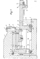
- the notching device according to the invention can be provided, for example, on a notching machine of the design described in US Pat. No. 4,129,054, by using a rearward arm 1 above a rearward arm on the vertically movable plunger gene machine table 2 is formed. It is then alternatively possible, with the upper knife provided on the front arm of the ram and the lower knife provided on the front machine table, to release constant angles of, for example, 90 °, while the rear of the notching machine for releasing variable angles between, for example, 30 ° and 120 ° reserved.
- the notching device comprises an upper knife 3 formed in one piece with a point angle of 30 ° between its two cutting edges and a lower knife 4 composed of two individual knives at the same point angle.
- the cutting tips of these two notching knives can be provided with a curve with a radius of curvature of 0.5 mm .
- the upper knife 3 is fixed to an upper adjusting ring 5 by means of bolts 6.
- the upper adjusting ring 5 is fixed in a center of rotation of the upper knife tip axis of rotation 7 by means of a pivot 8 and a nut 9 screwed thereon on the rear arm 1 of the plunger.
- a first guide groove 10 is formed on the upper adjusting ring 5 and has a circular curvature concentric with the axis of rotation 7.
- a projection 11 of a first sliding piece 12 surrounds, which is fixed by means of screws 13 on the rear arm 1 of the plunger and also has a circular curvature course which is concentric with the axis of rotation 7.
- the guide groove 10 and the slider 12 result in a guide length corresponding to a central angle of 150 ° for the upper adjusting ring 5.
- On the upper adjusting ring 5 there is also a guide pin in a rigid axis 14 parallel to the axis of rotation 7 15 formed, which fits into a guide bushing 16 of a lower adjusting ring 17 provided for fastening the lower knife 4.
- the two individual knives 18 and 19 of the lower knife 4 are arranged within a cutout 21 of this lower adjusting ring 17, this cutout 21 being connected to an opening 22 through which the sheet metal waste obtained can be removed.
- the lower adjusting ring 17 has a pivot pin 23 which runs in the axis of rotation 7 and which engages in a bearing bore of a fastening piece 25 fastened to the rear machine table 2 by means of bolts 24.
- the support of the lower adjusting ring 17 with respect to the rear machine table 2 obtained by means of the fastening piece 25 in the area of the axis of rotation 7 is supplemented in the area of the rigid axle 14 by a second slide piece 26, which is likewise fixed to the machine table 2 by means of bolts 27 and like the first one Slider 12 has a circular curvature concentric to the axis of rotation 7 with a guide length corresponding to a central angle of 150 °.
- the second slider 26 also has a projection 28 with which it fits into a second guide groove 29 of the lower adjusting ring 17.
- the adjusting rings 5 and 17 connected to one another via the rigid axis 14 can thus be pivoted together about the axis of rotation 7.
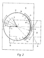
- the lower adjusting ring 17 is designed as an auxiliary table arranged parallel to the rear machine table 2, which is inserted in an opening 30 of a stop table 31 arranged plane-parallel with this auxiliary table.
- the stop table 31 is supported on the machine table 2 by four support columns 32 and by means of bolts 33 attached.
- T-slots (not shown in more detail) for adjustable table stops for the workpieces are formed in the stop table 31 and are held in place for the release by means of hold-down devices, also not shown.
- the lower adjusting ring 17 can be ascertained on the stop table 31 by means of a toggle handle arrangement 34 which comprises a circular guide segment 35 which is concentric with the axis of rotation 7 and also has a guide length corresponding to a central angle of 150 °.
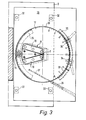
- an actuator in the form of a double-acting pressure cylinder 36 for the joint adjustment of the two adjusting rings 5 and 17 is also attached to the stop table 31, the piston rod 37 of this pressure cylinder being articulated on the lower adjusting ring 17.
- an NC-controlled spindle drive can also be provided as the actuator.
- the two adjusting rings 5 and 17 are also provided with an angle scale 38 which extends over 150 ° and in which two zero marks are provided which are oriented on the axis of rotation 7 with a central angle of 30 ° and with respect to which two halves of this angle scale each extend by 60 °.
- workpieces 39 can be placed on the auxiliary table formed by the lower adjusting ring 17 and the stop table 31. Notches are generated with the minimum tip angle of 30 ° specified for the two notching knives.
- the ver adjustable table stops of the stop table 31 created workpieces 39 are first provided in a first relative swivel position I of the upper knife 3 and thus a corresponding swivel position of the lower knife 4 with a first working stroke of the ram at an angle of 30 °.
- the two notching knives have to be adjusted by rotating the two adjusting rings 5 and 17 together about the axis of rotation 7 by means of the pressure cylinder 36 into a second swivel position II, whereupon the angle is adjusted to the desired finished dimension of 60 ° or 67 with a second working stroke of the ram , 5 ° is expanded.
- the determination of the second pivot position II is carried out by actuating the K lever handle arrangement 34, with which the lower adjusting ring 17 is detached from the stop table 31 and thus together with the upper adjusting ring 5 can be pivoted about the axis of rotation 7 along the angle scale 38, on which the Difference in angle to the larger angle can be read exactly, and it is thus also possible to set the second pivot position II precisely with a renewed actuation of the toggle grip arrangement 34.
- the pivoting of the two adjusting rings when the toggle grip arrangement is released can be done with or without the support of the pressure cylinder 36.
- the two set once pivoting positions I and II can be fixed by means of adjustable stops in the other, which then in conjunction with a suitable coupling of the B e-actuation of the pressure cylinder 36 provides the possibility of the working strokes of the plunger, that the two adjusting rings 5 and 17 for a successive machining of workpieces with two working strokes of the ram between these working strokes are automatically adjusted from the swivel position I to the swivel position II.
- the upper knife 3 can be composed of two individually replaceable individual knives.
- Both notching knives can also consist, for example, of three individual knives arranged in a triangle, with which it is then also possible by means of the notching device to produce correspondingly polygonal punchings in workpieces with at least two working strokes of the ram.
Landscapes
- Engineering & Computer Science (AREA)
- Mechanical Engineering (AREA)
- Perforating, Stamping-Out Or Severing By Means Other Than Cutting (AREA)
- Eye Examination Apparatus (AREA)
- Beans For Foods Or Fodder (AREA)
- Regulation And Control Of Combustion (AREA)
- Turning (AREA)
- Shearing Machines (AREA)
Priority Applications (1)
| Application Number | Priority Date | Filing Date | Title |
|---|---|---|---|
| AT83108645T ATE27416T1 (de) | 1982-09-07 | 1983-09-01 | Ausklinkvorrichtung. |
Applications Claiming Priority (2)
| Application Number | Priority Date | Filing Date | Title |
|---|---|---|---|
| DE3233208 | 1982-09-07 | ||
| DE3233208A DE3233208C1 (de) | 1982-09-07 | 1982-09-07 | Ausklinkvorrichtung |
Publications (3)
| Publication Number | Publication Date |
|---|---|
| EP0102625A2 true EP0102625A2 (fr) | 1984-03-14 |
| EP0102625A3 EP0102625A3 (en) | 1984-05-23 |
| EP0102625B1 EP0102625B1 (fr) | 1987-05-27 |
Family
ID=6172644
Family Applications (1)
| Application Number | Title | Priority Date | Filing Date |
|---|---|---|---|
| EP83108645A Expired EP0102625B1 (fr) | 1982-09-07 | 1983-09-01 | Dispositif d'encochage |
Country Status (5)
| Country | Link |
|---|---|
| US (1) | US4535665A (fr) |
| EP (1) | EP0102625B1 (fr) |
| JP (1) | JPS5988213A (fr) |
| AT (1) | ATE27416T1 (fr) |
| DE (2) | DE3233208C1 (fr) |
Cited By (2)
| Publication number | Priority date | Publication date | Assignee | Title |
|---|---|---|---|---|
| EP0329259A1 (fr) * | 1988-02-18 | 1989-08-23 | Walker-Hagou B.V. | Dispositif d'encochage |
| US6978764B1 (en) | 1999-10-18 | 2005-12-27 | Ford Global Technologies, Inc. | Control method for a vehicle having an engine |
Families Citing this family (9)
| Publication number | Priority date | Publication date | Assignee | Title |
|---|---|---|---|---|
| SE465360B (sv) * | 1984-05-02 | 1991-09-02 | Amada Co Ltd | Skaermaskin |
| DE3604516C2 (de) * | 1986-02-13 | 1993-09-30 | Boschert Ludwig Masch | Ausklinkvorrichtung |
| AT387172B (de) * | 1986-12-01 | 1988-12-12 | Haemmerle Ag | Winkelschere |
| IT1214004B (it) * | 1987-10-13 | 1990-01-05 | Eugenio Lenzotti | Macchina punzonatrice e tranciatrice con angolo di taglio variabile |
| DE3835775C1 (fr) * | 1988-10-20 | 1990-03-29 | Ludwig Boschert Maschinen- Und Apparatebau Gmbh & Co Kg, 7850 Loerrach, De | |
| DE3838197A1 (de) * | 1988-11-08 | 1990-05-10 | Muhr & Bender | Werkzeugmaschine |
| US5113733A (en) * | 1989-05-02 | 1992-05-19 | Link, Inc. | Adjustable angular shearing device |
| US5881591A (en) * | 1996-08-13 | 1999-03-16 | Ondracek; Carl | Automatic channel letter bending machine |
| JP3452533B2 (ja) * | 2000-05-11 | 2003-09-29 | ファナック株式会社 | 目的形状部切離し装置、該装置を搭載したロボット及び切離し方法 |
Family Cites Families (10)
| Publication number | Priority date | Publication date | Assignee | Title |
|---|---|---|---|---|
| DE7225345U (de) * | 1974-07-18 | Maschinenfabrik Weingarten Ag | Schneidvorrichtung für eine Presse zum Ausschneiden von Platinen aus einem durch das Werkzeug intermittierend hindurchgeführten streifen- oder bandförmigen Werkstoff, wie Blechband etc | |
| US2555069A (en) * | 1945-12-20 | 1951-05-29 | Verney Jean Louis Francois | Machine for cutting tubes and the like |
| DE2165224C3 (de) * | 1971-12-29 | 1974-07-18 | Iwk-Pressen Gmbh, 3503 Lohfelden | Stanzvorrichtung zur Anwendung in einer Stufenpresse |
| SE398836B (sv) * | 1974-10-16 | 1978-01-23 | Nordisk Kartro Ab | Maskin for kapning av trevirke |
| DE2601858C3 (de) * | 1976-01-20 | 1978-08-10 | Ludwig Boschert Maschinen- Und Apparatebau Gmbh & Co Kg, 7850 Loerrach | Stanzmaschine |
| US3996829A (en) * | 1976-02-23 | 1976-12-14 | Gianfranco Tromponi | Angular shearing machine for laminates, such as sheet metal |
| JPS52111080A (en) * | 1976-03-15 | 1977-09-17 | Kazutoshi Yamazaki | Method of obtaining blanks from material of specified length |
| US4327618A (en) * | 1977-01-31 | 1982-05-04 | Harvey Menard | Apparatus for cutting a strip of material |
| DE2931410A1 (de) * | 1979-08-02 | 1981-04-30 | Peddinghaus, Rolf, 5828 Ennepetal | Ausklinkvorrichtung |
| DE8200527U1 (de) * | 1982-01-13 | 1982-07-01 | F.I.M. S.r.l., 40127 Bologna | Eckenschere |
-
1982
- 1982-09-07 DE DE3233208A patent/DE3233208C1/de not_active Expired
-
1983
- 1983-09-01 DE DE8383108645T patent/DE3371750D1/de not_active Expired
- 1983-09-01 EP EP83108645A patent/EP0102625B1/fr not_active Expired
- 1983-09-01 AT AT83108645T patent/ATE27416T1/de not_active IP Right Cessation
- 1983-09-06 US US06/529,551 patent/US4535665A/en not_active Expired - Fee Related
- 1983-09-07 JP JP58165826A patent/JPS5988213A/ja active Pending
Cited By (2)
| Publication number | Priority date | Publication date | Assignee | Title |
|---|---|---|---|---|
| EP0329259A1 (fr) * | 1988-02-18 | 1989-08-23 | Walker-Hagou B.V. | Dispositif d'encochage |
| US6978764B1 (en) | 1999-10-18 | 2005-12-27 | Ford Global Technologies, Inc. | Control method for a vehicle having an engine |
Also Published As
| Publication number | Publication date |
|---|---|
| DE3371750D1 (en) | 1987-07-02 |
| EP0102625B1 (fr) | 1987-05-27 |
| EP0102625A3 (en) | 1984-05-23 |
| DE3233208C1 (de) | 1984-02-16 |
| ATE27416T1 (de) | 1987-06-15 |
| JPS5988213A (ja) | 1984-05-22 |
| US4535665A (en) | 1985-08-20 |
Similar Documents
| Publication | Publication Date | Title |
|---|---|---|
| DE2760355C2 (fr) | ||
| DE3223992A1 (de) | Spannvorrichtung | |
| DE10021302A1 (de) | Schleifmaschine und Verfahren zum Schärfen von Klingen | |
| DE3736438A1 (de) | Schleifmaschine, insbesondere zum schleifen von scherenteilen | |
| DE3233208C1 (de) | Ausklinkvorrichtung | |
| DE2355339B2 (de) | Präzisionshaltevorrichtung für zylindrische Werkstücke | |
| DE3508809A1 (de) | Biegevorrichtung | |
| DE3915555A1 (de) | Blechbiegemaschine | |
| WO2003035315A1 (fr) | Procede de sectionnement de pieces a usiner | |
| DE102004031584B4 (de) | Schärfmaschine zum Scharfschleifen von Klingen | |
| DE3604516C1 (de) | Ausklinkvorrichtung | |
| DE2809512A1 (de) | Drehbank | |
| DE2626943C3 (de) | Planfräswerkzeug | |
| DE2124862C3 (de) | Profilstahlschere | |
| EP1121217B1 (fr) | Dispositif et procede de production de platines | |
| DE4126014A1 (de) | Vorrichtung zum ausfuehren von arbeitsoperationen im raum mit kontrollierter bzw. gesteuerter tiefe | |
| DE19811418B4 (de) | Spannzange für eine Schneidmaschine | |
| DE2446459C2 (de) | Bolzenschweißvorrichtung | |
| DE4217947A1 (de) | Eckenschere mit integrierter stanzeinheit | |
| DE840041C (de) | Feststellvorrichtung fuer Kopierfraesmaschinen | |
| EP0052273A1 (fr) | Dispositif pour l'usinage de pièces | |
| AT383078B (de) | Anlage zum bearbeiten von schwarten laengsgeschnittener baumstaemme | |
| DE4037522C2 (fr) | ||
| DE4034155C1 (en) | Cutting notches in metal - involves starting tool and second tool to enlarge first cut | |
| DE150486C (fr) |
Legal Events
| Date | Code | Title | Description |
|---|---|---|---|
| PUAI | Public reference made under article 153(3) epc to a published international application that has entered the european phase |
Free format text: ORIGINAL CODE: 0009012 |
|
| AK | Designated contracting states |
Designated state(s): AT BE CH DE FR GB IT LI LU NL SE |
|
| PUAL | Search report despatched |
Free format text: ORIGINAL CODE: 0009013 |
|
| AK | Designated contracting states |
Designated state(s): AT BE CH DE FR GB IT LI LU NL SE |
|
| 17P | Request for examination filed |
Effective date: 19841023 |
|
| GRAA | (expected) grant |
Free format text: ORIGINAL CODE: 0009210 |
|
| AK | Designated contracting states |
Kind code of ref document: B1 Designated state(s): AT BE CH DE FR GB IT LI LU NL SE |
|
| PG25 | Lapsed in a contracting state [announced via postgrant information from national office to epo] |
Ref country code: NL Effective date: 19870527 Ref country code: BE Effective date: 19870527 |
|
| REF | Corresponds to: |
Ref document number: 27416 Country of ref document: AT Date of ref document: 19870615 Kind code of ref document: T |
|
| PG25 | Lapsed in a contracting state [announced via postgrant information from national office to epo] |
Ref country code: SE Effective date: 19870531 |
|
| REF | Corresponds to: |
Ref document number: 3371750 Country of ref document: DE Date of ref document: 19870702 |
|
| ET | Fr: translation filed | ||
| ITF | It: translation for a ep patent filed | ||
| PG25 | Lapsed in a contracting state [announced via postgrant information from national office to epo] |
Ref country code: AT Effective date: 19870901 |
|
| PG25 | Lapsed in a contracting state [announced via postgrant information from national office to epo] |
Ref country code: LU Free format text: LAPSE BECAUSE OF NON-PAYMENT OF DUE FEES Effective date: 19870930 |
|
| PLBI | Opposition filed |
Free format text: ORIGINAL CODE: 0009260 |
|
| NLV1 | Nl: lapsed or annulled due to failure to fulfill the requirements of art. 29p and 29m of the patents act | ||
| 26 | Opposition filed |
Opponent name: MUHR UND BENDER MASCHINENBAU GMBH Effective date: 19871001 |
|
| PLBM | Termination of opposition procedure: date of legal effect published |
Free format text: ORIGINAL CODE: 0009276 |
|
| STAA | Information on the status of an ep patent application or granted ep patent |
Free format text: STATUS: OPPOSITION PROCEDURE CLOSED |
|
| 27C | Opposition proceedings terminated |
Effective date: 19900320 |
|
| PGFP | Annual fee paid to national office [announced via postgrant information from national office to epo] |
Ref country code: CH Payment date: 19910730 Year of fee payment: 9 |
|
| PGFP | Annual fee paid to national office [announced via postgrant information from national office to epo] |
Ref country code: GB Payment date: 19910805 Year of fee payment: 9 |
|
| PGFP | Annual fee paid to national office [announced via postgrant information from national office to epo] |
Ref country code: FR Payment date: 19910913 Year of fee payment: 9 |
|
| ITTA | It: last paid annual fee | ||
| PGFP | Annual fee paid to national office [announced via postgrant information from national office to epo] |
Ref country code: DE Payment date: 19911128 Year of fee payment: 9 |
|
| PG25 | Lapsed in a contracting state [announced via postgrant information from national office to epo] |
Ref country code: GB Effective date: 19920901 |
|
| PG25 | Lapsed in a contracting state [announced via postgrant information from national office to epo] |
Ref country code: LI Effective date: 19920930 Ref country code: CH Effective date: 19920930 |
|
| GBPC | Gb: european patent ceased through non-payment of renewal fee |
Effective date: 19920901 |
|
| PG25 | Lapsed in a contracting state [announced via postgrant information from national office to epo] |
Ref country code: FR Effective date: 19930528 |
|
| REG | Reference to a national code |
Ref country code: CH Ref legal event code: PL |
|
| PG25 | Lapsed in a contracting state [announced via postgrant information from national office to epo] |
Ref country code: DE Effective date: 19930602 |
|
| REG | Reference to a national code |
Ref country code: FR Ref legal event code: ST |