EP0102676B1 - LKW mit schwenkbarem Führerhaus welches in der Fahrposition teilweise von den Schwenkzylindern gestützt wird - Google Patents
LKW mit schwenkbarem Führerhaus welches in der Fahrposition teilweise von den Schwenkzylindern gestützt wird Download PDFInfo
- Publication number
- EP0102676B1 EP0102676B1 EP83201296A EP83201296A EP0102676B1 EP 0102676 B1 EP0102676 B1 EP 0102676B1 EP 83201296 A EP83201296 A EP 83201296A EP 83201296 A EP83201296 A EP 83201296A EP 0102676 B1 EP0102676 B1 EP 0102676B1
- Authority
- EP
- European Patent Office
- Prior art keywords
- cabin
- piston
- cylinder
- cab
- drive position
- Prior art date
- Legal status (The legal status is an assumption and is not a legal conclusion. Google has not performed a legal analysis and makes no representation as to the accuracy of the status listed.)
- Expired
Links
- 239000012530 fluid Substances 0.000 claims description 18
- 230000000712 assembly Effects 0.000 description 5
- 238000000429 assembly Methods 0.000 description 5
- 230000035939 shock Effects 0.000 description 3
- 239000006096 absorbing agent Substances 0.000 description 2
- 238000010586 diagram Methods 0.000 description 2
- 230000000694 effects Effects 0.000 description 2
- 230000005484 gravity Effects 0.000 description 2
- 230000003247 decreasing effect Effects 0.000 description 1
- 239000007788 liquid Substances 0.000 description 1
- 238000005086 pumping Methods 0.000 description 1
- 239000000725 suspension Substances 0.000 description 1
Images
Classifications
-
- B—PERFORMING OPERATIONS; TRANSPORTING
- B62—LAND VEHICLES FOR TRAVELLING OTHERWISE THAN ON RAILS
- B62D—MOTOR VEHICLES; TRAILERS
- B62D33/00—Superstructures for load-carrying vehicles
- B62D33/06—Drivers' cabs
- B62D33/063—Drivers' cabs movable from one position into at least one other position, e.g. tiltable, pivotable about a vertical axis, displaceable from one side of the vehicle to the other
- B62D33/067—Drivers' cabs movable from one position into at least one other position, e.g. tiltable, pivotable about a vertical axis, displaceable from one side of the vehicle to the other tiltable
Definitions
- the invention relates to a device for tilting a vehicle cabin from and into the drive position, said device comprising at least one hydraulic piston-cylinder device forming a hydraulic circuit together with a pump, a reservoir for the hydraulic fluid, and a control valve, the ends of said piston-cylinder device being pivotally connected to the cabin and the vehicle chassis respectively, there being a by-pass connection between the cylinder chambers on either side of the piston when the latter is in the region of its innermost position corresponding to the drive position of the cabin, said by-pass connection permitting the piston and therefore the cabin in the drive position to perform a limited reciprocating movement while the pump is inoperative.
- tilt-cab truck is known from NL-A--7215364.
- tilt-cab trucks such as the one disclosed in the above mentioned Dutch application
- the tiltable cab is supported by springs while in the drive position. Due to the presence of the by-pass connection between the two cylinder spaces in the innermost piston position, the piston is permitted to follow the up and down elastic movements of the cab relative to the chassis, occurring during driving, with a corresponding inward and outward sliding movement relative to the cylinder.
- the tilt cylinders are no longer "on-line" when the cab is in the over-the-road position, and the entire weight of the cab must be supported by the springs and/or other suspension and shock absorber elements.
- the invention is characterized by the fact that the cylinder chamber under the piston is in direct connection with an accumulator in that the accumulator is connected to the hydraulic circuit between the control valve and the cylinder chamber under the piston and that said control valve has, in addition to a position for tilting and a position for returning to the drive position, a third position in which the feed passages to the cylinder spaces on either side of the piston are disconnected from the pump and the reservoir.
- control valve into the third, or drive position.
- this may be done manually, but it also may be done automatically, e.g. at the end of a tilting movement back to the drive position.
- driving hydraulic fluid is permitted to flow from the accumulator towards the cylinder space under the piston in order to allow the cabin to carry out an upward elastic movement, while, when the cabin falls back under the force of gravity, hydraulic fluid is permitted to flow from that space towards the accumulator.
- the adjustable restriction has a shock dampening effect.
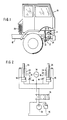
- FIG. 1 illustrate a tilt cab truck in which a tiltable cabin 10 is mounted on a vehicle chassis 12.
- the cabin 10 is tiltable in the forward direction around a shaft 14 situated in the front portion of the chassis 12.
- the connection between the cabin 10 and the shaft 14 is constituted at both sides of the vehicle by a toggle-lever 16 which acts as a spring permitting a certain up and down movement of the cabin 10 relative to the chassis 12 during driving.
- a bracket 18 is mounted on each side of the cabin 10, and, the back end of the cabin 10 rests on one or more spring devices 20 supported by the chassis 12.
- Reference number 22 indicates the hydraulic tilting device, which includes a piston cylinder assembly 24.
- the upper piston rod end 26 of the piston rod assembly 24 is pivotally connected at 28 to the cabin 10, and the lower end of the cylinder 30 is pivotally connected at 32 to the chassis 12.
- a similar piston cylinder assembly is provided at each side of the cabin 10.
- Figure 1 also shows an accumulator 34 connected to the cylinder 30.
- the accumulator 34 will be discussed further with reference to Figure 2.
- both piston cylinder assemblies 24 of the hydraulic tilting device 22 are operatively connected to a hydraulic control valve 36, a hydraulic pump 38, and a reservoir 40 for the hydraulic fluid.
- Both piston cylinder assemblies 24 are provided with a by-pass conduit 42 containing a restriction 44.
- the by-pass conduits connect the chambers below and above the pistons 46. Accordingly, the pistons 46 and therefore the cabin 10 are permitted to carry out restricted up and down movements, during which hydraulic fluid is displaced through the by-pass conduits 42.
- the hydraulic control valve 36 has three positions namely a position for tilting the cabin 10 forwardly, a position for returning the cabin 10 from the forwardly tilted position, and a drive, or over-the-road, position.
- the control valve 36 is in its most rightward position, which is its tilting position. If the pump 38 is actuated manually or through an air motor while the hydraulic control valve 36 is in this position, hydraulic pressurized fluid is supplied to both sides of the pistons 46 of both piston cylinder assemblies 24. Because of the difference in effective piston areas above and below the pistons, the pistons 46 move outwardly, causing the cabin 10 to rotate around the tilting shaft 14 and causing the cabin 10 to lift off the spring device 20.
- Tilting the cabin 10 backwards to the drive position as shown in Figure 1 is achieved by sliding the control valve 36 to its most leftward position. In that position of the control valve 36, hydraulic fluid is supplied only to the piston rod sides of the cylinder 30, and the spaces below the piston 46 are communicated with the reservoir 40. As soon as the pistons 46 have retracted so far that the spaces above and below the pistons 46 have been connected through the by-pass conduits 42, the pump 38 may be turned off. Due to the effect of the by-pass conduits 42, the cabin 10 then continues to move further downwardly under the force of gravity towards its rest position, in which the cabin weight is balanced by the spring device 20 and the toggle lever 16.
- the operation of the tilting device as shown corresponds to that of the device according to the earlier mentioned Dutch patent application.
- the tilting device now additionally acts as an elastic support for the cabin 10 in the drive position.
- the hydraulic control valve 36 has a third position which is a middle position in the embodiment shown. In the third position, the supply of hydraulic fluid via the pump 38 to the cylinders 24 and the return of hydraulic fluid from the cylinders 24 to the reservoir 40 have both been disconnected.
- the hydraulic control valve 36 is placed in the third position before the entire cabin weight is rested on the spring device(es) 20 and the toggle lever 16. Placing the hydraulic control valve 36 into the third position may be accomplished automatically- e.g., as a response to the decrease of the operating pressure prevailing in the tilting cylinders 30 to a suitable lower value (e.g., 50 bar) or when a predetermined cabin position has been reached. If the operator later desires to adjust the cabin height, this may be done by increasing or decreasing the quantity of hydraulic fluid in the system. It will be clear that this may be done by placing the control valve 36 in one of its extreme positions for a short time interval, and (if necessary) pumping additional fluid into the system via the pump 38 or draining a quantity of fluid from the system to the reservoir 40.
- a suitable lower value e.g. 50 bar
- the cabin weight in the drive position is borne at least partially by the piston cylinder assemblies 24.
- the by-pass conduits 42 permit a certain up and down movement of the pistons 46 in the cylinders 30 when the cabin is in its drive position. If the cabin 10 moves downwardly, more fluid is freed from the chambers below the pistons 46 than will fit in the chambers above the pistons 46 because of the rod volume. This fluid surplus is received in the accumulator 34, which is connected to the cylinders 30 below the pistons 46. If the cabin 10 moves upwardly, the reverse takes place. The fluid which then is necessary for "make-up" in the chambers below the pistons 46 is supplied by the accumulator 34 under the influence of the pressure prevailing therein in the gas space above the liquid.
- the restrictions 44 in the by-pass conduits 42 are preferably adjustable, to permit the operator to vary the resistance to the passage of hydraulic fluid from the chambers below the pistons 46 to those above the pistons and vice versa. In any event, the restrictions 44 provide a certain resistance to passage of hydraulic fluid so that the elastic upward and downward movements of the cabin are dampened. In this manner the piston cylinder assemblies 24 simultaneously act as shock absorbers.
Landscapes
- Engineering & Computer Science (AREA)
- Chemical & Material Sciences (AREA)
- Combustion & Propulsion (AREA)
- Transportation (AREA)
- Mechanical Engineering (AREA)
- Body Structure For Vehicles (AREA)
- Vehicle Body Suspensions (AREA)
- Component Parts Of Construction Machinery (AREA)
Claims (4)
Applications Claiming Priority (2)
| Application Number | Priority Date | Filing Date | Title |
|---|---|---|---|
| US415232 | 1982-09-07 | ||
| US06/415,232 US4463818A (en) | 1982-09-07 | 1982-09-07 | Tilt cab truck in which the cab is partially supported by the tilting cylinder while in the drive position |
Publications (3)
| Publication Number | Publication Date |
|---|---|
| EP0102676A2 EP0102676A2 (de) | 1984-03-14 |
| EP0102676A3 EP0102676A3 (en) | 1985-07-03 |
| EP0102676B1 true EP0102676B1 (de) | 1987-07-29 |
Family
ID=23644874
Family Applications (1)
| Application Number | Title | Priority Date | Filing Date |
|---|---|---|---|
| EP83201296A Expired EP0102676B1 (de) | 1982-09-07 | 1983-09-07 | LKW mit schwenkbarem Führerhaus welches in der Fahrposition teilweise von den Schwenkzylindern gestützt wird |
Country Status (8)
| Country | Link |
|---|---|
| US (1) | US4463818A (de) |
| EP (1) | EP0102676B1 (de) |
| JP (1) | JPS59501543A (de) |
| AU (1) | AU554931B2 (de) |
| CA (1) | CA1201737A (de) |
| DE (1) | DE3372740D1 (de) |
| ES (1) | ES8502038A1 (de) |
| WO (1) | WO1984000928A1 (de) |
Families Citing this family (26)
| Publication number | Priority date | Publication date | Assignee | Title |
|---|---|---|---|---|
| FR2547108B1 (fr) * | 1983-05-30 | 1986-07-04 | Gratzmuller Claude | Commande oleopneumatique pour disjoncteurs electriques |
| US4748809A (en) * | 1984-07-31 | 1988-06-07 | Aisin-Warner Limited | Hydraulic servo mechanism of automatic transmission for vehicle |
| DE3602362A1 (de) * | 1986-01-27 | 1987-07-30 | Man Nutzfahrzeuge Gmbh | Ventilanordnung fuer einen hydraulischen druckspeicher |
| FR2630788A2 (fr) * | 1988-02-05 | 1989-11-03 | Bendix France | Dispositif de fuite pour vidange d'un accumulateur a membrane |
| US5044455A (en) * | 1990-02-16 | 1991-09-03 | Navistar International Transportion Corp. | Actively controlled truck cab suspension |
| DE19607969A1 (de) * | 1996-03-01 | 1997-09-04 | Fiat Om Carrelli Elevatori | Flurförderzeug mit einer höhenverstellbaren Stand- und/oder Sitzplattform |
| JP3120736B2 (ja) * | 1996-08-02 | 2000-12-25 | 三菱自動車工業株式会社 | キャブオーバ型車両の安全装置 |
| US6070681A (en) * | 1997-06-13 | 2000-06-06 | Lord Corporation | Controllable cab suspension |
| GB9719577D0 (en) * | 1997-09-16 | 1997-11-19 | Hendrickson Europ Limited | Suspension systems |
| SE513464C2 (sv) * | 1999-02-12 | 2000-09-18 | Scania Cv Ab | Anordning vid förarhytter för fordon |
| US7152842B1 (en) * | 2000-01-24 | 2006-12-26 | Lockheed Martin Corporation | User coupled workspace shock isolation system |
| NL1016315C2 (nl) * | 2000-10-03 | 2002-04-04 | Actuant Corp | Hydraulische kantelinrichting voor het kantelen van een voertuigcabine en voertuig voorzien van een dergelijke kantelinrichting. |
| NL1016668C2 (nl) * | 2000-11-21 | 2002-05-22 | Actuant Corp | Hydraulische kantelinrichting voor het kantelen van een voertuigcabine en voertuig voorzien van een dergelijke kantelinrichting. |
| GB0226843D0 (en) * | 2002-11-16 | 2002-12-24 | Cnh Uk Ltd | cab support system for an agricultural vehicle |
| CL2003002178A1 (es) * | 2003-10-27 | 2005-03-18 | Maquinaria Y Tecnologia Bio Bi | Maquina trineumatica tipo tractor que cuenta con un chasis formado por tres secciones, en que las dos primeras forman una base y la tercera seccion se proyecta por sobre la parte posterior de la segunda seccion, formadas por bastidores. |
| US7475895B2 (en) * | 2004-06-15 | 2009-01-13 | Delphi Technologies, Inc. | Hydraulic circuit for a stabilizer bar |
| SE529537C2 (sv) * | 2006-01-17 | 2007-09-04 | Volvo Lastvagnar Ab | Anslutningsenhet för en lastbil |
| DE102006052086A1 (de) * | 2006-11-04 | 2008-05-08 | Wilhelm Karmann Gmbh | Hydraulischer Aktuator zur Betätigung einer mechanischen Vorrichtung |
| DK2229471T3 (da) * | 2008-01-08 | 2015-06-22 | Treadstone Technologies Inc | Stærkt elektrisk ledende overflader til elektrokemiske anvendelser |
| GB0810634D0 (en) * | 2008-06-11 | 2008-07-16 | Valtra Oy Ab | Rotation system |
| FR2965021B1 (fr) * | 2010-09-22 | 2015-04-03 | Snecma | Verin hydraulique pour systeme de commande de l'orientation des pales de soufflante d'un turbopropulseur. |
| US8448735B2 (en) * | 2011-10-31 | 2013-05-28 | Deere & Company | Cab tilt with multifunction flag pin and locking cylinder |
| US10494040B2 (en) | 2017-09-05 | 2019-12-03 | Cnh Industrial America Llc | Tilting system for a suspended cab of a work vehicle |
| US10668954B2 (en) | 2017-11-30 | 2020-06-02 | John Payne | Cab and hood suspension with hood tilt |
| JP7306965B2 (ja) * | 2019-11-05 | 2023-07-11 | トヨタ自動車株式会社 | 貨物車両 |
| CN113911217A (zh) * | 2020-07-11 | 2022-01-11 | 道依茨法尔机械有限公司 | 一种轮式拖拉机的悬浮驾驶室减震结构 |
Family Cites Families (13)
| Publication number | Priority date | Publication date | Assignee | Title |
|---|---|---|---|---|
| US3054260A (en) * | 1962-09-18 | Dickinson | ||
| US29938A (en) * | 1860-09-04 | Improvement in harvesters | ||
| NL161401C (nl) * | 1972-11-13 | 1982-04-16 | Applied Power Inc | Hydraulische aandrijfinrichting voor de kantelcabine van een vrachtwagen. |
| GB1431599A (en) * | 1973-10-31 | 1976-04-07 | Dewandre Co Ltd C | Hydraulic cab-tilting systems |
| US3985194A (en) | 1974-08-30 | 1976-10-12 | Applied Power Inc. | Tilt cab power stream and valve control therefor |
| US3938770A (en) * | 1974-10-07 | 1976-02-17 | Caterpillar Tractor Co. | Method and apparatus for hydraulically suspending a vehicle seat |
| ES453731A1 (es) * | 1976-11-27 | 1977-11-16 | Pedro Roquet S A | Perfeccionamientos introducidos en los dispositivos de ac- cionamiento de cabinas rebatibles para camiones y demas ve- hiculos industriales. |
| DE2806247C2 (de) * | 1978-02-15 | 1983-03-17 | Daimler-Benz Ag, 7000 Stuttgart | Luftfedersystem für Fahrerhäuser von Nutzfahrzeugen |
| DE2853806C2 (de) * | 1978-12-13 | 1984-05-30 | Fritzmeier AG, 5036 Oberentfelden | Stützeinheit für eine Fahrerkabine an Nutzfahrzeugen |
| GB2048383B (en) * | 1979-03-28 | 1983-04-27 | Rmstrong Patents Co Ltd | Road vehicles |
| SE8103234L (sv) * | 1980-07-02 | 1982-01-03 | Weber Oelhydraulik | Hydraulisk anordning for stjelpning av forarhytter hos lastbilar |
| JPS5779304A (en) * | 1980-10-31 | 1982-05-18 | Hino Motors Ltd | Fluid passage changeover valve for hydraulic cylinder |
| US4359867A (en) * | 1981-03-03 | 1982-11-23 | International Harvester Co. | Seat accumulator clutch booster assist |
-
1982
- 1982-09-07 US US06/415,232 patent/US4463818A/en not_active Expired - Fee Related
-
1983
- 1983-08-31 AU AU20359/83A patent/AU554931B2/en not_active Ceased
- 1983-08-31 WO PCT/US1983/001339 patent/WO1984000928A1/en not_active Ceased
- 1983-08-31 JP JP58503092A patent/JPS59501543A/ja active Granted
- 1983-09-06 CA CA000436114A patent/CA1201737A/en not_active Expired
- 1983-09-06 ES ES525414A patent/ES8502038A1/es not_active Expired
- 1983-09-07 EP EP83201296A patent/EP0102676B1/de not_active Expired
- 1983-09-07 DE DE8383201296T patent/DE3372740D1/de not_active Expired
Also Published As
| Publication number | Publication date |
|---|---|
| ES525414A0 (es) | 1984-12-16 |
| EP0102676A3 (en) | 1985-07-03 |
| AU2035983A (en) | 1984-03-29 |
| CA1201737A (en) | 1986-03-11 |
| WO1984000928A1 (en) | 1984-03-15 |
| JPS6257547B2 (de) | 1987-12-01 |
| ES8502038A1 (es) | 1984-12-16 |
| US4463818A (en) | 1984-08-07 |
| JPS59501543A (ja) | 1984-08-30 |
| AU554931B2 (en) | 1986-09-04 |
| EP0102676A2 (de) | 1984-03-14 |
| DE3372740D1 (en) | 1987-09-03 |
Similar Documents
| Publication | Publication Date | Title |
|---|---|---|
| EP0102676B1 (de) | LKW mit schwenkbarem Führerhaus welches in der Fahrposition teilweise von den Schwenkzylindern gestützt wird | |
| US3948341A (en) | Tilt cab truck | |
| US3944017A (en) | Suspension for truck cab | |
| US2757376A (en) | Autoamtic load responsive suspension for vehicles | |
| EP0121968B1 (de) | Hydraulische Fahrerhaus-Aufhängung | |
| EP0530366B1 (de) | Niveauregelung fur kraftfahrzeuge | |
| US4396202A (en) | Leveling system for motor vehicles | |
| US3853368A (en) | Hydraulic piston-cylinder device having means for permitting limited reciprocating motion | |
| US4223906A (en) | Installation for lowering a kickstand arranged on a motorcycle | |
| US4872702A (en) | Suspension system for vehicles | |
| GB2271746A (en) | Suspension system for motor vehicles | |
| US5685563A (en) | Counterbalance system for short wheelbase vehicles | |
| US1291016A (en) | Fluid-cushion device for automobiles. | |
| EP0427269A1 (de) | Motorrad mit höhenverstellbarer Karosserie | |
| CN112243413A (zh) | 用于带水平调节的车辆底盘的减振器单元 | |
| US4283087A (en) | Support unit for a driver's cab in a utility vehicle | |
| US4424872A (en) | Truck | |
| US3390892A (en) | Installation for the automatic adjustment of the floor height of a vehicle | |
| US2869892A (en) | Hydraulic stabilizing system for vehicles | |
| EP1335850A1 (de) | Hydraulische kippvorrichtung für fahrerhäuser von lastkraftwagen, und kraftfahrzeug mit derartiger kippvorrichtung | |
| US4960291A (en) | Automotive suspension system | |
| US3212789A (en) | Device for the adjustment of the height of vehicles, particularly motor vehicles | |
| US5033762A (en) | Suspension system for a sidecar motorcycle | |
| US2904346A (en) | Self-leveling suspension assembly for vehicles | |
| US8777543B2 (en) | Rollback carrier gravity tilt dampening system |
Legal Events
| Date | Code | Title | Description |
|---|---|---|---|
| PUAI | Public reference made under article 153(3) epc to a published international application that has entered the european phase |
Free format text: ORIGINAL CODE: 0009012 |
|
| AK | Designated contracting states |
Designated state(s): DE FR GB IT NL SE |
|
| PUAL | Search report despatched |
Free format text: ORIGINAL CODE: 0009013 |
|
| AK | Designated contracting states |
Designated state(s): DE FR GB IT NL SE |
|
| 17P | Request for examination filed |
Effective date: 19851202 |
|
| 17Q | First examination report despatched |
Effective date: 19860704 |
|
| GRAA | (expected) grant |
Free format text: ORIGINAL CODE: 0009210 |
|
| AK | Designated contracting states |
Kind code of ref document: B1 Designated state(s): DE FR GB IT NL SE |
|
| REF | Corresponds to: |
Ref document number: 3372740 Country of ref document: DE Date of ref document: 19870903 |
|
| ITF | It: translation for a ep patent filed | ||
| ET | Fr: translation filed | ||
| PLBE | No opposition filed within time limit |
Free format text: ORIGINAL CODE: 0009261 |
|
| STAA | Information on the status of an ep patent application or granted ep patent |
Free format text: STATUS: NO OPPOSITION FILED WITHIN TIME LIMIT |
|
| 26N | No opposition filed | ||
| ITTA | It: last paid annual fee | ||
| PGFP | Annual fee paid to national office [announced via postgrant information from national office to epo] |
Ref country code: SE Payment date: 19940812 Year of fee payment: 12 |
|
| PGFP | Annual fee paid to national office [announced via postgrant information from national office to epo] |
Ref country code: FR Payment date: 19940818 Year of fee payment: 12 |
|
| PGFP | Annual fee paid to national office [announced via postgrant information from national office to epo] |
Ref country code: DE Payment date: 19940822 Year of fee payment: 12 |
|
| PGFP | Annual fee paid to national office [announced via postgrant information from national office to epo] |
Ref country code: GB Payment date: 19940825 Year of fee payment: 12 |
|
| PGFP | Annual fee paid to national office [announced via postgrant information from national office to epo] |
Ref country code: NL Payment date: 19940930 Year of fee payment: 12 |
|
| EAL | Se: european patent in force in sweden |
Ref document number: 83201296.7 |
|
| PG25 | Lapsed in a contracting state [announced via postgrant information from national office to epo] |
Ref country code: GB Effective date: 19950907 |
|
| PG25 | Lapsed in a contracting state [announced via postgrant information from national office to epo] |
Ref country code: SE Effective date: 19950908 |
|
| PG25 | Lapsed in a contracting state [announced via postgrant information from national office to epo] |
Ref country code: NL Effective date: 19960401 |
|
| GBPC | Gb: european patent ceased through non-payment of renewal fee |
Effective date: 19950907 |
|
| PG25 | Lapsed in a contracting state [announced via postgrant information from national office to epo] |
Ref country code: FR Effective date: 19960531 |
|
| PG25 | Lapsed in a contracting state [announced via postgrant information from national office to epo] |
Ref country code: DE Effective date: 19960601 |
|
| NLV4 | Nl: lapsed or anulled due to non-payment of the annual fee |
Effective date: 19960401 |
|
| EUG | Se: european patent has lapsed |
Ref document number: 83201296.7 |
|
| REG | Reference to a national code |
Ref country code: FR Ref legal event code: ST |