EP0102723A1 - Kraftstoffeinspritzventil nach Scheibenart - Google Patents
Kraftstoffeinspritzventil nach Scheibenart Download PDFInfo
- Publication number
- EP0102723A1 EP0102723A1 EP83304157A EP83304157A EP0102723A1 EP 0102723 A1 EP0102723 A1 EP 0102723A1 EP 83304157 A EP83304157 A EP 83304157A EP 83304157 A EP83304157 A EP 83304157A EP 0102723 A1 EP0102723 A1 EP 0102723A1
- Authority
- EP
- European Patent Office
- Prior art keywords
- injector
- spacer
- electromagnet
- armature
- synthetic resin
- Prior art date
- Legal status (The legal status is an assumption and is not a legal conclusion. Google has not performed a legal analysis and makes no representation as to the accuracy of the status listed.)
- Withdrawn
Links
Images

Classifications
-
- G—PHYSICS
- G01—MEASURING; TESTING
- G01N—INVESTIGATING OR ANALYSING MATERIALS BY DETERMINING THEIR CHEMICAL OR PHYSICAL PROPERTIES
- G01N29/00—Investigating or analysing materials by the use of ultrasonic, sonic or infrasonic waves; Visualisation of the interior of objects by transmitting ultrasonic or sonic waves through the object
- G01N29/22—Details, e.g. general constructional or apparatus details
- G01N29/222—Constructional or flow details for analysing fluids
-
- F—MECHANICAL ENGINEERING; LIGHTING; HEATING; WEAPONS; BLASTING
- F02—COMBUSTION ENGINES; HOT-GAS OR COMBUSTION-PRODUCT ENGINE PLANTS
- F02M—SUPPLYING COMBUSTION ENGINES IN GENERAL WITH COMBUSTIBLE MIXTURES OR CONSTITUENTS THEREOF
- F02M51/00—Fuel-injection apparatus characterised by being operated electrically
- F02M51/06—Injectors peculiar thereto with means directly operating the valve needle
- F02M51/061—Injectors peculiar thereto with means directly operating the valve needle using electromagnetic operating means
- F02M51/0625—Injectors peculiar thereto with means directly operating the valve needle using electromagnetic operating means characterised by arrangement of mobile armatures
- F02M51/0635—Injectors peculiar thereto with means directly operating the valve needle using electromagnetic operating means characterised by arrangement of mobile armatures having a plate-shaped or undulated armature not entering the winding
- F02M51/0639—Injectors peculiar thereto with means directly operating the valve needle using electromagnetic operating means characterised by arrangement of mobile armatures having a plate-shaped or undulated armature not entering the winding the armature acting as a valve
-
- F—MECHANICAL ENGINEERING; LIGHTING; HEATING; WEAPONS; BLASTING
- F02—COMBUSTION ENGINES; HOT-GAS OR COMBUSTION-PRODUCT ENGINE PLANTS
- F02M—SUPPLYING COMBUSTION ENGINES IN GENERAL WITH COMBUSTIBLE MIXTURES OR CONSTITUENTS THEREOF
- F02M51/00—Fuel-injection apparatus characterised by being operated electrically
- F02M51/06—Injectors peculiar thereto with means directly operating the valve needle
- F02M51/08—Injectors peculiar thereto with means directly operating the valve needle specially for low-pressure fuel-injection
-
- G—PHYSICS
- G01—MEASURING; TESTING
- G01N—INVESTIGATING OR ANALYSING MATERIALS BY DETERMINING THEIR CHEMICAL OR PHYSICAL PROPERTIES
- G01N29/00—Investigating or analysing materials by the use of ultrasonic, sonic or infrasonic waves; Visualisation of the interior of objects by transmitting ultrasonic or sonic waves through the object
- G01N29/02—Analysing fluids
- G01N29/024—Analysing fluids by measuring propagation velocity or propagation time of acoustic waves
-
- H—ELECTRICITY
- H01—ELECTRIC ELEMENTS
- H01F—MAGNETS; INDUCTANCES; TRANSFORMERS; SELECTION OF MATERIALS FOR THEIR MAGNETIC PROPERTIES
- H01F7/00—Magnets
- H01F7/06—Electromagnets; Actuators including electromagnets
- H01F7/08—Electromagnets; Actuators including electromagnets with armatures
- H01F7/16—Rectilinearly-movable armatures
- H01F7/1638—Armatures not entering the winding
-
- F—MECHANICAL ENGINEERING; LIGHTING; HEATING; WEAPONS; BLASTING
- F02—COMBUSTION ENGINES; HOT-GAS OR COMBUSTION-PRODUCT ENGINE PLANTS
- F02M—SUPPLYING COMBUSTION ENGINES IN GENERAL WITH COMBUSTIBLE MIXTURES OR CONSTITUENTS THEREOF
- F02M2200/00—Details of fuel-injection apparatus, not otherwise provided for
- F02M2200/07—Fuel-injection apparatus having means for avoiding sticking of valve or armature, e.g. preventing hydraulic or magnetic sticking of parts
-
- F—MECHANICAL ENGINEERING; LIGHTING; HEATING; WEAPONS; BLASTING
- F02—COMBUSTION ENGINES; HOT-GAS OR COMBUSTION-PRODUCT ENGINE PLANTS
- F02M—SUPPLYING COMBUSTION ENGINES IN GENERAL WITH COMBUSTIBLE MIXTURES OR CONSTITUENTS THEREOF
- F02M2200/00—Details of fuel-injection apparatus, not otherwise provided for
- F02M2200/90—Selection of particular materials
- F02M2200/9015—Elastomeric or plastic materials
-
- G—PHYSICS
- G01—MEASURING; TESTING
- G01N—INVESTIGATING OR ANALYSING MATERIALS BY DETERMINING THEIR CHEMICAL OR PHYSICAL PROPERTIES
- G01N2291/00—Indexing codes associated with group G01N29/00
- G01N2291/02—Indexing codes associated with the analysed material
- G01N2291/021—Gases
- G01N2291/0212—Binary gases
-
- G—PHYSICS
- G01—MEASURING; TESTING
- G01N—INVESTIGATING OR ANALYSING MATERIALS BY DETERMINING THEIR CHEMICAL OR PHYSICAL PROPERTIES
- G01N2291/00—Indexing codes associated with group G01N29/00
- G01N2291/10—Number of transducers
- G01N2291/101—Number of transducers one transducer
Definitions
- This invention relates to plate-type electromagnetically operated fuel injectors for internal combustion engines.
- the closure member is in the form of a plate or disc formed in a material such that it constitutes the armature of the electromagnet of the injector.
- the energised condition is normally the open condition and the degree of movement of the member from its closed to its open position is critical to the operating characteristics of the injector. It follows therefore that after accurate setting of the gap which exists between the spacer and the member in the de-energised condition the gap should not alter in use of the injector.
- a plate-type electromagnetic fuel injector includes a spacer against which the armature of the electromagnet abuts, said spacer being formed from a material which is non-magnetic, electrically insulating, resultant to attack bythe fuel, and dimensionally stable when subject to, and able to withstand, repeated impact loading by the armature of the electromagnet.
- an electrically insulating material has additional advantages in that it reduces eddy current losses in the valve, thus speeding up both the pull-in and drop-out characteristics of the injector. Such improvement of the drop-out characteristic permits a weaker armature return spring to be utilized thus further speeding-up the pull-in characteristic (opening) of the injector.
- the spacer is formed from a synthetic resin material.
- the synthetic resin material is a film-type polyester.
- the synthetic resin material is a ; film-type polyester having a repeat unit of C 10 H 8 0 4 which is resistant to attack by petroleum hydrocarbon fuels and which is non-malleable in use.
- the film-type polyester is polyethylene- terephthalate.
- the synthetic resin spacer is formed from a so-called “paper” formed of an aromatic . polyamide, conveniently that material sold under the Trade Name "NOMEX”.
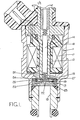
- the fuel injector is an electromagnetic valve of the plate-type, that is to say having a plate or disc-like member as its closure member, the closure member also being the armature of the electromagnet of the injector.
- the injector comprises a hollow, generally cylindrical outer body 11 formed from steel and having a fuel inlet 12 at one end thereof.
- a hollow steel core 13 having extending therethrough a passage 14 which connects the inlet 12 with an outlet 15 of the body 11.
- a moulded synthetic resin coil former 16 upon which is wound an electromagnet winding 17.
- the winding 17 thus encircles the core 13.
- Adjacent the outlet 15 the body'll defines an integral, radially inwardly extending circumferential shoulder 18 against which a steel annulus 19 is trapped by a steel valve seat member 21.
- the valve seat member 21 is in the form of a disc the diameter of which is equal to the internal diameter of the body 11, the disc 21 having a centrally disposed fuel flow passage or metering orifice 22.
- the core 13 terminates short of the valve seat member 21 and the face of the member 21 presented to the end of the core 13 is shaped to provide an annular land 23 encircling the end of the passage 22.
- the closure member 24 of the injector Positioned within the annulus 19 between the member 21 and the end of the core 13 is the closure member 24 of the injector.
- the closure member 24 (which is also the armature of the electromagnet 13, 17) is in the form of a steel disc slidably received within the annulus 19 and having extending therethrough a plurality of bores 25 arranged in a circular row about the central axis of the disc.
- the diameter of the circular row of bores 25 is greater than the diameter of the land 23 on the face of the member 21, and a compression spring 26 housed within the core 13 urges the closure member 24 into engagement with the land 23 on the face of the valve seat member 21. This is the closed position of the injector since engagement of the member 24 with the land 23 prevents flow of fuel between the inlet 12 and outlet 15 of the body 11.
- the internal diameter of the shoulder 18 is less than the internal diameter of the annulus 19, and thus the shoulder 18 overlies the outer peripheral region of the closure member 24.
- the thickness of the closure member 24 is less than the thickness of the annulus 19 by a predetermined amount to permit the closure member 24 to move by said predetermined amount from the closed position to an open position where the closure member is arrested by the shoulder 18. In this position, which is achieved by energising the winding 17 so that the member 24 is magnetically attracted to the core 13, fuel can flow through the passage of the core 13, across the upper face of the closure member 24, through the bores 25 of the closure member 24, beneath the closure member 24 over the top of the land 23, and through the passage 22 of the valve seat member 21 to the outlet 15.
- a non-magnetic spacer 27 is placed between the shoulder 18 and the closure member 24 (see Figure 2).
- the spacer 27 thus prevents contact between the steel closure member 24 and the steel shoulder 18, and thus improves the "drop-out" characteristic of the electromagnet of the valve. Additionally therefore a simple drive circuit for the electromagnet can be utilized since accurate drive pulse shaping is not essential.
- the non-magnetic spacer 27 is in the form of an annulus of a film-type polyester synthetic resin material and is trapped in place against the shoulder 18 by being trapped between the shoulder 18 and the annulus 19.
- the electrical insulation characteristic of the spacer 27 is found to minimise eddy current losses in the iron circuit of the electromagnet, and thus is found to improve the "drop-out" characteristic of the electromagnet.
- the improved "drop-out” characteristic in turn permits a weaker spring 26 to be utilized than would otherwise have been the case, and the use of a weaker spring of course improves the "pull-in" characteristic.
- the actual material from which the spacer 27 is constructed must fulfil certain requirements. Firstly the material must be resistant to the petroleum hydrocarbon fuels which the injector is to control. The material must also be non-magnetic and electrically insulating. Furthermore, the material must be dimensionally stable when subjected repeatedly to the impact of the closure member 24 in use, that is to say the material must be non-malleable, in use. The distance through which the closure member 24 is permitted to move relative to the core 13 is a critical factor in a fuel injector.
- the material of the spacer 27 is not dimensionally stable when subject to repeated impact, and, for example, the spacer is caused to become thinner, then the distance through which the closure member 24 is permitted to move will increase, and correspondingly the gap between the closure member and the core 13 in the energised position will be reduced.
- the dimensional.stability must be retained over a suitable temperature range bearing in mind the environment of the ⁇ injector.
- the material of the spacer 27 must be dimensionally stable over the range -40°C to 170°C.
- the spacer member 27 is desirably very thin (conveniently no great than 0.006 inches), it is convenient to manufacture the spacer 27 from a film-forming synthetic resin material.
- a film-forming synthetic resin material Amongst those materials which are suitable for use in an injector for petroleium hydrocarbon fuel are the polyester films sold under the Trade Names "MYLAR”, “MELINEX”, and "HOSTOPHAN”.
- spacer 27 There may be other synthetic resin materials from which the spacer 27 could be produced.
- a suitable material will fulfil the following criteria. It will be magnetically and electrically non-conductive, it will be inert with respect to the relevant fuel, primarily petroleum hydrocarbon fuels, and it will be non-malleable in use.
- a suitable test for resistance to attack by petroleum fuel is to immerse the spacer in ASTM Reference fuel C (i.e. iso-octane/ toluene) at 60°C for 240 hours. A satisfactory spacer material will survive this test without evidence of cracking, crazing, softening or embrittlement and with a percentage weight change not exceeding 2.5%, and will also survive a 3 month immersion at 21°C with a weight change not exceeding 1.0%.
- ASTM Reference fuel C i.e. iso-octane/ toluene
- a suitable test for non-malleability in use is to construct an injector using a material to be tested and to subject the injector to 500 million cycles of operation (opening and closing being one cycle).
- the spacer material can be said to be sufficiently non-malleable if the calibration of the injector does not change significantly during the test.
- the film-type polyester "MYLAR" which is well suited to constitute the spacer 27 is polyethylene terephthalate, a film-type polyester having a repeat unit of C 10 H 8 0 4 .
- the repeat unit molecular weight is 192 but a typical commercial polymer having this repeat unit would have a molecular weight average between 20,000 and 30,000.
Landscapes
- Engineering & Computer Science (AREA)
- Physics & Mathematics (AREA)
- Chemical & Material Sciences (AREA)
- Electromagnetism (AREA)
- Analytical Chemistry (AREA)
- Combustion & Propulsion (AREA)
- Life Sciences & Earth Sciences (AREA)
- Acoustics & Sound (AREA)
- General Engineering & Computer Science (AREA)
- Biochemistry (AREA)
- General Health & Medical Sciences (AREA)
- General Physics & Mathematics (AREA)
- Immunology (AREA)
- Pathology (AREA)
- Health & Medical Sciences (AREA)
- Mechanical Engineering (AREA)
- Power Engineering (AREA)
- Fuel-Injection Apparatus (AREA)
- Polyesters Or Polycarbonates (AREA)
Applications Claiming Priority (2)
| Application Number | Priority Date | Filing Date | Title |
|---|---|---|---|
| GB8221972 | 1982-07-29 | ||
| GB8221972 | 1982-07-29 |
Publications (1)
| Publication Number | Publication Date |
|---|---|
| EP0102723A1 true EP0102723A1 (de) | 1984-03-14 |
Family
ID=10532001
Family Applications (1)
| Application Number | Title | Priority Date | Filing Date |
|---|---|---|---|
| EP83304157A Withdrawn EP0102723A1 (de) | 1982-07-29 | 1983-07-18 | Kraftstoffeinspritzventil nach Scheibenart |
Country Status (5)
| Country | Link |
|---|---|
| EP (1) | EP0102723A1 (de) |
| JP (1) | JPS5941660A (de) |
| AU (1) | AU1735983A (de) |
| BR (1) | BR8304032A (de) |
| ZA (1) | ZA835285B (de) |
Cited By (5)
| Publication number | Priority date | Publication date | Assignee | Title |
|---|---|---|---|---|
| EP0200866A1 (de) * | 1985-05-07 | 1986-11-12 | VDO Adolf Schindling AG | Einspritzventil |
| EP0186323A3 (en) * | 1984-12-24 | 1986-12-17 | General Motors Corporation | Electromagnetic fuel injector |
| EP0304745A1 (de) * | 1987-08-25 | 1989-03-01 | WEBER S.r.l. | Schnelles Elektroventil, insbesondere Brennstoffeinspritzsteuerventil für Dieselmotoren |
| EP0314337A1 (de) * | 1987-10-27 | 1989-05-03 | LUCAS INDUSTRIES public limited company | Benzineinspritzventil |
| WO1995014166A1 (en) * | 1993-11-19 | 1995-05-26 | Korostashevsky Vladimir Markov | Electromagnetic nozzle for injecting fuel into an internal combustion engine |
Families Citing this family (6)
| Publication number | Priority date | Publication date | Assignee | Title |
|---|---|---|---|---|
| DE68905502T2 (de) * | 1988-02-05 | 1993-09-23 | Lucas Ind Plc | Brennstoffeinspritzventil. |
| JPH01315661A (ja) * | 1988-06-15 | 1989-12-20 | Japan Electron Control Syst Co Ltd | 内燃機関の電磁式燃料噴射弁 |
| DE3834447A1 (de) * | 1988-10-10 | 1990-04-12 | Mesenich Gerhard | Elektromagnetisches einspritzventil und verfahren zu dessen herstellung |
| JP2539522B2 (ja) * | 1988-12-28 | 1996-10-02 | 株式会社日立製作所 | 電磁式燃料噴射弁 |
| JPH036047U (de) * | 1989-06-06 | 1991-01-22 | ||
| JPH0830458B2 (ja) * | 1989-10-30 | 1996-03-27 | 株式会社ユニシアジェックス | フューエルインジェクタ |
Citations (4)
| Publication number | Priority date | Publication date | Assignee | Title |
|---|---|---|---|---|
| DE1576463A1 (de) * | 1967-03-29 | 1970-05-21 | Bosch Gmbh Robert | Einspritzventil fuer Kraftstoffeinspritzanlagen |
| JPS5535135A (en) * | 1978-09-01 | 1980-03-12 | Nippon Denso Co Ltd | Electromagnetic fuel injection valve |
| DE2942853A1 (de) * | 1978-11-01 | 1980-05-14 | Bendix Corp | Elektromagnetisches kraftstoffeinspritzventil |
| EP0026060A1 (de) * | 1979-09-20 | 1981-04-01 | LUCAS INDUSTRIES public limited company | Brennstoffeinspritzdüse |
-
1983
- 1983-07-18 EP EP83304157A patent/EP0102723A1/de not_active Withdrawn
- 1983-07-20 ZA ZA835285A patent/ZA835285B/xx unknown
- 1983-07-27 AU AU17359/83A patent/AU1735983A/en not_active Abandoned
- 1983-07-28 BR BR8304032A patent/BR8304032A/pt unknown
- 1983-07-29 JP JP58137929A patent/JPS5941660A/ja active Pending
Patent Citations (4)
| Publication number | Priority date | Publication date | Assignee | Title |
|---|---|---|---|---|
| DE1576463A1 (de) * | 1967-03-29 | 1970-05-21 | Bosch Gmbh Robert | Einspritzventil fuer Kraftstoffeinspritzanlagen |
| JPS5535135A (en) * | 1978-09-01 | 1980-03-12 | Nippon Denso Co Ltd | Electromagnetic fuel injection valve |
| DE2942853A1 (de) * | 1978-11-01 | 1980-05-14 | Bendix Corp | Elektromagnetisches kraftstoffeinspritzventil |
| EP0026060A1 (de) * | 1979-09-20 | 1981-04-01 | LUCAS INDUSTRIES public limited company | Brennstoffeinspritzdüse |
Non-Patent Citations (1)
| Title |
|---|
| Patent Abstracts of Japan Vol. 4, no. 72, 27 May 1980 Page 61 M 13 & JP-A-55 035135 * |
Cited By (6)
| Publication number | Priority date | Publication date | Assignee | Title |
|---|---|---|---|---|
| EP0186323A3 (en) * | 1984-12-24 | 1986-12-17 | General Motors Corporation | Electromagnetic fuel injector |
| EP0200866A1 (de) * | 1985-05-07 | 1986-11-12 | VDO Adolf Schindling AG | Einspritzventil |
| EP0304745A1 (de) * | 1987-08-25 | 1989-03-01 | WEBER S.r.l. | Schnelles Elektroventil, insbesondere Brennstoffeinspritzsteuerventil für Dieselmotoren |
| US4928888A (en) * | 1987-08-25 | 1990-05-29 | Weber S.R.L. | Fast solenoid valve, particularly a fuel injection pilot valve for diesel engines |
| EP0314337A1 (de) * | 1987-10-27 | 1989-05-03 | LUCAS INDUSTRIES public limited company | Benzineinspritzventil |
| WO1995014166A1 (en) * | 1993-11-19 | 1995-05-26 | Korostashevsky Vladimir Markov | Electromagnetic nozzle for injecting fuel into an internal combustion engine |
Also Published As
| Publication number | Publication date |
|---|---|
| AU1735983A (en) | 1984-02-02 |
| ZA835285B (en) | 1984-03-28 |
| JPS5941660A (ja) | 1984-03-07 |
| BR8304032A (pt) | 1984-03-07 |
Similar Documents
| Publication | Publication Date | Title |
|---|---|---|
| US6808133B1 (en) | Fuel injection valve | |
| US6168135B1 (en) | Slotted housing for fuel injector | |
| JP2000505863A (ja) | 電磁作動式の弁 | |
| KR900002015A (ko) | 전자기 밸브 | |
| EP0314337B1 (de) | Benzineinspritzventil | |
| JPS5941660A (ja) | プレ−ト形電磁燃料噴射装置 | |
| US4233585A (en) | Plunger type electromagnet | |
| US4660770A (en) | Electromagnetic fuel injector | |
| EP2835520A1 (de) | Kraftstoffeinspritzvorrichtung und Verfahren zum Betreiben einer Kraftstoffeinspritzvorrichtung | |
| AU4534897A (en) | Magnetic core-coil assembly for spark ignition systems | |
| GB2124430A (en) | An electromgnetic fuel injector with a plate-type armature | |
| JPH04507125A (ja) | 電磁作動式の燃料噴射弁 | |
| EP1138934A2 (de) | Zweispuliges elektromagnetisches Einspritzventil | |
| US5086980A (en) | Fuel injector for an internal combustion engine | |
| GB2201039A (en) | A solenoid valve for a fuel injection pump of an internal combustion engine | |
| DE3627499A1 (de) | Fluessigkeitsstandanzeiger | |
| EP0665374A1 (de) | Elektromagnet zur Steuern des Dosierventils eines Kraftstoffeinspritzventils | |
| US20020158155A1 (en) | Fuel injection valve | |
| KR20060021303A (ko) | 연소 기관의 연료 분사 밸브 | |
| GB2146846A (en) | Temperature compensated solenoid device | |
| DE102006055088B4 (de) | Elektromagnetisches Einspritzventil und Verfahren zu seiner Herstellung sowie Verwendung eines Magnetkerns für ein elektromagnetisches Einspritzventil | |
| JPH081161B2 (ja) | 電磁操作される燃料噴射弁 | |
| EP2172641B1 (de) | Aktuator und Einspritzventil | |
| US2356577A (en) | Electromagnetic control for injectors of internal-combustion engines | |
| GB2213650A (en) | Fuel injection valve |
Legal Events
| Date | Code | Title | Description |
|---|---|---|---|
| PUAI | Public reference made under article 153(3) epc to a published international application that has entered the european phase |
Free format text: ORIGINAL CODE: 0009012 |
|
| AK | Designated contracting states |
Designated state(s): DE FR IT |
|
| STAA | Information on the status of an ep patent application or granted ep patent |
Free format text: STATUS: THE APPLICATION IS DEEMED TO BE WITHDRAWN |
|
| 18D | Application deemed to be withdrawn |
Effective date: 19841115 |
|
| RIN1 | Information on inventor provided before grant (corrected) |
Inventor name: KENNING, JOHN HERBERT |