EP0103022A1 - Ferngesteuerter ausschalter - Google Patents
Ferngesteuerter ausschalter Download PDFInfo
- Publication number
- EP0103022A1 EP0103022A1 EP83900440A EP83900440A EP0103022A1 EP 0103022 A1 EP0103022 A1 EP 0103022A1 EP 83900440 A EP83900440 A EP 83900440A EP 83900440 A EP83900440 A EP 83900440A EP 0103022 A1 EP0103022 A1 EP 0103022A1
- Authority
- EP
- European Patent Office
- Prior art keywords
- circuit breaker
- lever
- connecting element
- assembly
- link
- Prior art date
- Legal status (The legal status is an assumption and is not a legal conclusion. Google has not performed a legal analysis and makes no representation as to the accuracy of the status listed.)
- Granted
Links
Images




Classifications
-
- H—ELECTRICITY
- H01—ELECTRIC ELEMENTS
- H01H—ELECTRIC SWITCHES; RELAYS; SELECTORS; EMERGENCY PROTECTIVE DEVICES
- H01H89/00—Combinations of two or more different basic types of electric switches, relays, selectors and emergency protective devices, not covered by any single one of the other main groups of this subclass
- H01H89/06—Combination of a manual reset circuit with a contactor, i.e. the same circuit controlled by both a protective and a remote control device
- H01H89/08—Combination of a manual reset circuit with a contactor, i.e. the same circuit controlled by both a protective and a remote control device with both devices using the same contact pair
-
- H—ELECTRICITY
- H01—ELECTRIC ELEMENTS
- H01H—ELECTRIC SWITCHES; RELAYS; SELECTORS; EMERGENCY PROTECTIVE DEVICES
- H01H71/00—Details of the protective switches or relays covered by groups H01H73/00 - H01H83/00
- H01H71/04—Means for indicating condition of the switching device
Definitions
- the present invention relates to a remote control circuit breaker, the moving contact assembly of which is kept on or off by means of a bistable electromagnetic device.
- this type of circuit breaker uses a tilting mechanism which maintains a lever and a moving contact assembly in the on or off position, so that the force required to operate the lever is maximum at center of stroke of the lever due to the spring force of the rocking mechanism. Therefore, in the case where such a circuit breaker is controlled by means of a remote control electromagnet assembly, as the attraction thereof is inversely proportional to the square of the width of the main air gap, the maximum force needs to be applied to the center of the stroke of the joystick, requiring an increase in the power of the electromagnet assembly. Thus, the circuit breaker leaves something to be desired in that the electromagnet assembly is large in size or that the excitation current of the windings is increased.
- circuit breakers contain two electromagnets to ensure the switching on or off of the circuit breaker, which makes them unsatisfactory in that they are inevitably large.
- one of the objects of the invention is to provide a remote control circuit breaker which makes it possible to reduce the force applied to the remote control electromagnet assembly and to globally miniaturize the circuit breaker.
- the present invention is characterized in that a trigger link element, a lock link element, a movable contact, a control link element and a lever are mutually coupled, the trigger link element and the locking connecting element establishing the respective return springs and being locked p 1 their spring force so that the engagement or retention neck pure of a movable contact assembly supported by the locking connecting element depends on the holding force of a polarized bistable remote control electromagnet linked to the lever.
- such an arrangement is devoid of holding force to keep the handle in clenching or cutting, so that the operating force of the handle is equal to zero, but that the spring force of a contact pressure application spring when the circuit breaker is engaged is that of a return spring for the locking connecting element when it is cut off, simply provides the force necessary to bring the lever for the engaged position or the cut-off position.
- the electromagnet assembly of the bistable polarized type can be used so that the attraction of its permanent magnet is adjusted for allow the handle to be held in its engaged or disengaged position in opposition to the spring pressures of the contact pressure application spring and the return spring.
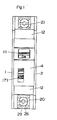
- a casing A (body of the circuit breaker), as visible in FIG. 6, mainly comprises a general casing l, an inner casing 2, a side casing 3 and an upper cover 4, the inner casing 2 having a top plate lla and a riser plate llb and substantially closing therewith the lateral and upper openings of the general casing 1, the lateral casing 3 covering the external surface of the internal casing 2, so that the general casing 1, the internal casing 2 and the lateral casing 3 are secured by means of eyelet pins 8 inserted in three assembly holes 5 to 7 formed in the general casing 1 and in the side casing 3.
- the upper cover 4 of elastic plastic material is fixed to fixing walls 9 and 10 at the upper ends of the general casing 1 and of the lateral casing 3 and on the lateral edges of the top plate 11a of the inner casing 2, and it has end wings 12 extending outwards starting from the two ends of the upper cover 4.
- At the lower end of the casing A are formed in the general casing 1 assembly grooves 19 which serve to mount the circuit breaker on a panel or the like.
- Terminals mainly include main terminals 20 and 21 for the power lines, a control terminal 22 for a remote control signal and an associated auxiliary terminal, the main terminals 20 and 21 comprising respective terminal sets (21) on the supply side and (20) on the use side, the terminal blocks (20) and (21) comprising terminal segments 24 and 25, washers 26 with engaging projections, spring washers 27, square nuts 28 and terminal screws 29, respectively.
- the terminal segments 24 and 25 are bent downwards at their lateral edge to form respective descending tongues 31 and 32, the terminal assemblies 20 and 21 being assembled to shoulders 15 and 16 situated at the lower part of the two sides of envelope A, respectively.
- the control terminal 22 comprises U-shaped terminal clamps 36 and terminal screws 37 which are screwed into the upper bent portions of the stirrups, and it is fixed to an upper shoulder 18 formed in the inner casing 2, the three terminal stirrups 36 being each engaged on a fixed slot 39 formed in the shoulder 18 and immovablely clamping the shoulder 18 by their elastic pressure effect.
- the auxiliary terminal 23 comprises three terminal segments 40 and terminal screws 41 and it is mounted on the upper shoulder 17 of the inner casing 2 on one side of the terminal assembly 20 on the use side.
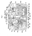
- the electrical circuit between the main terminals 20 and 21 mainly comprises a contact assembly 43, an electromagnet assembly of the plunger type 44 and a bimetallic strip 45, as visible in FIG. 6, which are arranged substantially in alignment with the terminals main 20 and 21, the contact assembly 43 used to switch the circuit and comprising a fixed contact 46 and a movable contact assembly 48 comprising a movable contact 47 and being positioned by a partition 50 which rises upwards to separate a arc extinguishing chamber of a control electromagnet housing 52.
- a slot 55 into which is inserted a multi-strand copper wire 52 or a conductive plate which connects the fixed contact segment 33 and the terminal segment 25 by welding, as shown ble in Figure 5.
- the movable contact assembly 48 comprises a movable contact plate 57, a contact bracket 58, a contact pressure application spring 59 and the movable contact 47, the movable contact plate 57 and the contact stirrup 58 being articulated by their upper part by means of a pivot 60, the contact pressure application spring 59 being placed in compression between the contact plate 57 and the contact stirrup 58 and at -Dessus the pivot 60, as shown in figures 5 and 6, which allows the contact plate 57 come into contact resiliently Q e an intermediate lower Por- tion thereof with the end / of the yoke contact 58, thereby maintaining the contact plate 57 in a stable state, the movable contact 47 being fixed to the lower end of the movable contact plate 57, and an opening 62 in the form of a keyhole intended to open at force contact being formed at this location above the mobil contact e 47.
- the movable contact assembly 48 has a fixing hole 61a at the lower end and above the opening 62, which makes it possible to engage an axis 63 in the hole 61a and to articulate the contact stirrup 58 with a connecting element or locking rod 64 which will be considered below, thanks to which the movable contact 47 comes into contact with the fixed contact 46 as shown in FIG. 5.
- the plunger type solenoid assembly 44 serves to detect a short circuit current, and it includes a yoke 65, a winding 66, a winding carcass 67, a fixed iron core 68, a spring reminder 69, a plunger 70 and a movable rod 71, the cylinder head 65 comprising a U-shaped frame 72 and a support plate 73 assembled and secured thereto by square holes 77 in the plate 73 in which the projections are mated 76 of frame 72.
- the cylinder head 65 is in one piece with a frame 79 intended to carry a mechanism 78 which will be described later.
- a side plate 82 of electrically conductive material, such as copper or a copper alloy, is placed upright and facing the other side plate 80 and it is fitted by square holes 83 on projections 81 of the frame with U-shaped profile 72 with mating connection.
- the support plate 73 is bent at its lower end from which it extends to form an arc confinement plate 84, and the plunger type electromagnet assembly 44 is placed on a support base provided by the general casing l, the arc confinement plate 84 coming into contact with the underside of the support base la so that the base la is caught between the electromagnet assembly 44 and the plate arc containment 84.
- Two axes 87 and 88 for the mechanism 78 are arranged on either side of receiving bores 89 of the general casing 1 and of the inner casing 2 and on either side of bores of reception 90 of the general casing 1 and of the interior casing 2, and they penetrate through the bores 91 and 92 of the chassis 79 thus maintaining the chassis 79 and coming into abutment against the side plate 82 adjacent to the interior casing 2, thus ensuring the positioning of the cylinder head 65 and of the chassis 79.
- the iron core fixes 68 p with a through hole 68a is fitted in a bore 93 at the bottom of the U-shaped frame 72 and crimped thereto by stamping, the movable rod 71 being longer than the iron core 68 and being slidably inserted in the through bore 68a.
- the winding carcass 67 has at one of its ends a portion of smaller diameter 94 which fits in a fixing bore 95 formed in the support plate 73, and it is adapted at its other end on the core of fixed iron 68.
- the plunger 70 is adapted to slide in the winding carcass 67 and a forced contact opening rod 96 starting from one of the ends of the plunger 70 comes out through the small diameter portion 94 of the winding carcass 67, so that a collar 97 located at the very end of the rod 96 passes through a large diameter portion of the hole-shaped opening lock 62 and is placed in the slot thereof.
- the return spring 96 is compressed between the fixed iron core 68 and the plunger 70.
- the electromagnet assembly 44 when a nominal current of the winding 66 or an overcurrent y simply circulates, restricts the movement of the plunger 70 by the thrust of the return spring 69, but when a short-circuit current flows, the magnetic flux between the fixed iron core 68 and the plunger 70 believes to overcome the action the return spring 69, from which follows that the plunger 70 is attracted by the fixed iron core 63 and that it approaches it. Therefore, the movable rod 71 is pushed towards the plunger 70 and it advances outside the U-shaped frame 72, and the collar 97 of the forced contact opening rod 96 is retained by the slot of the opening 62, which makes it pull the movable contact plate 57.
- the bimetallic strip 45 is curved approximately in the shape of an L, and it comprises a horizontal segment and an oblique segment, the oblique segment having at its upper end a spacing adjustment screw 100 screwed into that -this, the horizontal segment 98 having a crimping hole (not shown) by which the bimetallic strip 45 is crimped by stamping at the lower end of the side plate 82, the bimetallic strip 45 and the winding 66 being connected by a wire welded flexible copper 101, the side plate 82 and the movable contact plate 57 being connected by a welded flexible copper wire 102.
- the bimetallic strip 45 curves by causing the oblique segment to move apart of the terminal assembly 20, the curvature phenomenon being tared so that it is caused by an overcurrent of approximately several times the nominal intensity.
- the terminal assembly (21) on the supply side and the terminal assembly (20) on the use side are connected by the multi-strand copper connection wire 56, the fixed contact plate 57, the multi-strand copper wire 102, the chassis side plate 82, the bimetallic strip 45, the multi-strand copper wire 101 and the winding 26, in this order, and the interlocking and tripping control is operated by the assembly of contact 43.
- the arc extinguishing chamber 51 allows the arc to which the contact assembly 43 gives rise to quickly leave contacts 46 and 47 and to disappear, and it mainly comprises an evacuation orifice 103, arc confinement plates 84 and 104, a deionization grid 105 and an evacuation plate 106.
- the mechanism 78 comprises a connecting element trigger 109, an elé locking link 64, a control link 110, a lever 111 and a control solenoid assembly 112, the trigger link 109 comprising an ascending segment 113, a side segment 114 and a segment ear-shaped 115, the lateral segment 114 and the ear-shaped segment 115 having respective axis holes 116, which makes it possible to introduce an axis 87 into the holes 91 of the lateral frame 79 and of the plate lateral 82 on the bimetal side 45 of these, and to mount it pivoting at its two ends in the support holes 89 formed in the general casing 1 and in the internal casing 2.
- the ascending segment 113 of the trigger connecting element 109 is positioned at the lower front end of the movable rod 71 of the plunger-type electromagnet assembly 44 and at the upper end in front of the screw spacing adjustment 100 of the bimetallic strip 45, the lateral segment 114 advancing at an angle upwards and forming a hooked descending portion 119 at the upper oblique flank of its end and a circular arc surface 120 at its upper edge.
- a helical return spring 121 is fitted on the axis 87 to the level of the triggering connecting element 109, and it is retained at one of its ends 121a against the oblique lower edge of the lateral segment 114, and retained at its other end by abutting against the upper segment of the cylinder head 65.
- the trigger connecting element 109 is biased angularly anticlockwise in FIG. 5, and the lower end of the ascending segment 113 bears against the end of the movable rod. 71 so as to be able to be retained against the projecting face of the fixed iron core 68.
- the locking link member 64 includes a pair of elongated side segments 122 and 123 connected by a bridge segment 124 and has holes 125 in which engages an axis 88 which has passed through the holes 92 of the side frame 79 and of the side plate 82 and which is pivotally mounted at its two ends in the support holes 90 of the general casing 1 and of the internal casing 2, the axis 88 carrying a helical return spring 127.
- the helical spring 127 is retained at one of its ends by the upper segment of the cylinder head 65 and at its other ends by the lateral edges of the lateral segments 122 and 123 , so that the locking connecting element 64 is adapted to be biased angularly in the clockwise direction of FIG. 7 by the return force of the spring 127 and to be able to be retained at the lower end by the upper edge of the support plate 73.
- the upper end of the locking link member 64 intersects with that of the trigger link member 109, and a latch 128 located at the bottom end of the bridge segment 124 is located above the angular travel of the hook portion 119 of the trigger connecting element 109.
- the trigger link member 109 and the latch link member 64 are placed in the reset state, the trigger link member 109 being held in the position in which the adjustment screw bimetallic strip 100 and the movable rod 71 are detected by the ascending segment 113.
- the trigger connecting element 109 acts, the locking connecting element 64 is released therefrom and placed in the triggering state.
- the pin 63 intended to support the movable contact assembly 43 is pivotally mounted in the holes 129 of the lower end of the locking connecting element 64.
- the handle 111 is formed of an insulating material and it is inserted into a handle insertion notch 130a of the top plate 11a of the inner casing 2 and into a handle insertion slot 130b of the upper cover 4 so as to be rotatably supported by a pin 131 pivoting in bores 131a of the general casing 1 and of the inner casing 2.
- the lever 111 carries indicator plates lllb each of which is in an arc starting from one of the two sides of the latter, and it is provided at its lower end with a coupling bore 133 and, on the right side, an arm 134 advancing approximately horizontally, the arm 134 comprising a plunger coupling bore 135 ( Figure 8).
- the connecting element or control rod 110 is formed by an H-profile plate bent on both sides in the same direction, and it comprises the two lateral segments 136 and a bridge segment 137, the two lateral segments 136 being coupled at one of their ends to the coupling bore 133 by a pivot 138 and at their other end to the pivot 60 supporting the movable contact plate 57 and the contact bracket 58.
- the lever 111 of FIG. 9 is turned to the right and it is placed in the running position, thus pushing the crew of the movable contact 48 via the control link element 110.
- the locking link element 64 is locked to the trigger link element 109
- the movable contact element 48 rotates around the rod 63 to bring the movable contact assembly 47 into contact with the fixed contact 46.
- the movable frame 57 then rotates around the rod 60 because the contacts 47 and 46 are both in mutual contact to compress the compression spring 59, which applies the contact pressure to the contact assembly 43 and keeps the circuit breaker in the on position thanks to the electromagnet assembly 112 which will be described later.
- a trip display assembly 139 operates a trip display when the circuit breaker is tripped by an abnormal current, and it comprises a display link 139a and a conjugation rod 139b, as visible in FIG. 8, the display link 139a being articulated at its lower end to the lever axis 131 and having at its upper end a trigger display sector (the surface of which is marked as "DECL" in an arc of a circle.
- the conjugation rod 139b comprises an angled rod at both ends in the same direction, and it is connected to the upper ends of the display link 139a and of the locking connection element 64. In the reset state, the trigger display assembly 139 is retracted from the stop position of the lever 111, as shown in FIGS.
- the connecting element of verro uillage 64 rotates clockwise to push the conjugation rod 139b, and it rotates the display link 139a to allow the trigger display sector 139c to come and cover the display plate of walking lllb (the lever 111 is still in the on position). It follows that the mention "DECL” carried by the trigger display sector 139c appears in the slot 130b and that the mention "ON" becomes invisible.
- control electromagnet assembly 112 is mounted in a housing 52 of the general casing 1 so that the outlet side of the plunger 140 remains oriented upwards.
- the plunger 140 being coupled by its upper end to a plunger coupling bore 135 of the lever 111 by means of a U-shaped rod 141.
- the assembly at control electromagnet 112 is of the bistable polarized type, and it comprises, as visible in FIG.
- a winding carcass 143 providing a rectangular through hole 144 and upper and lower cheeks 145 and 146, a winding 147, a pair of interior breech elements 148 bearing against the two lateral flanks of the winding carcass 143, a pair of permanent magnets 149 (whose magnetic poles are represented by N and S) attracted against the exterior surfaces of the breech elements inner 148, and a pair of outer yoke elements attracted to the outer flanks of the permanent magnets 149, respectively.
- the plunger 140 passes through the rectangular bore 144 of the winding carcass 143, and it has cheeks 151 and 152 placed between the inner breech elements 148 and the outer breech elements 150, respectively.
- a coupling stud 153 which has at its upper end an engagement bore 153a in which the U-rod 141. is pivotally received.
- a damper 154 is interposed between and below the lower ends of the external cylinder head elements 150 in order to dampen the displacements of the plunger 140.
- the upper and lower ends 148a and 148b of the lower yoke elements 148 all have magnetization of polarity S, and those of the outer yoke elements 150 have a magnetization of polarity N, and they face each other.
- the cheeks 151 and 152 of the plunger 140 when they are placed as represented by one or the other of FIGS. 9 and 10, are attracted by the cylinder head elements 148 or 150 and secured to them. this.
- a compression return spring 155 is interposed between the arm 135 of the lever 11 and the winding carcass 143, the force return spring 155 being weaker than the attraction towards the plunger 140, but acting when the lever 111 is placed in the on position by manual operation or by the electromagnet assembly 112, which immediately causes the separation of the contacts 46 and 47.
- the electromagnet assembly 112 When the electromagnet assembly 112 is not energized, the start or stop position is effected by manual operation of the lever 111, which makes the plunger 140 descend or rise with maintaining the latter in the lower or upper position by the magnetic force of the permanent magnets 149, which keeps the lever 111 in its on or off position.
- the moving contact assembly 48 is kept in contact with the fixed contact 46 with contact pressure as shown in FIG.
- a fixed contact stirrup with U-profile 160 is fitted on a fixed projection 161 and a pair of switching contact blades 162 and 163 are carried by slots 165a and 165b of a support projection 164 facing the projection 165 with pinching so as to come into contact with the fixed contact bracket 160 on the upper surfaces and lower of it respectively.
- a bore 166 in an arc is formed between the fixed projection 161 and the support projection 164, and a switching contact control lever 167 formed on one side of the arm 134 of the lever 111 and forming a single piece with the arm 134 perforates the bore 166 to be positioned between the switching contacts 162 and 163, so that when the lever 111 is in the on position ( Figure 9), the lever 167 separates the lower switching contact blade 163 from the fixed contact blade 160, and that, when it is in the off position ( Figure 10), it separates the upper switch contact blade 162 thereof.
- the ends of the winding 147 are connected to the fixed contact blade 160 and to one of the control terminals 22 and the diodes 156 and 157 are connected by one of their ends to the pair of movable contact blades 162 and 163 so that their polarities are mutually opposite and by their other end to the other control terminal 22, as shown in FIG. 14.
- the reference numeral 167 denotes an AC power source and the reference numeral 168 an external inverter.
- the external inverter when the external inverter is in the active position, a unidirectional current flows in the winding 147 passing through the diode 156, so that the plunger 140 passes from the high position of FIG. 10 to the low position of the FIG.
- the locking connecting element 64 is released from the triggering connecting element 109 and it pivots under the action of the spring 127 as shown in FIGS. 11 and 12, from which follows that the pivot 63 rotates and that the movable contact assembly 48 rotates on the axis 138 under the action of the control link element 110.
- the movable contact 47 is separated from the fixed contact 46 without actuation of the plunger 153 of the electromagnet assembly 112 or of the lever 111, which executes the operation without tripping for separating the movable contact 47 from the fixed contact 46.
- the above embodiment constitutes a three-wire device.
- the control terminal in common to the diodes 156 and 157 and for the external inverter 168 to be provided with a pair of diodes 169 and 170, and the operating principle is the same as that of the three-wire device.
- a direct voltage is applied to excite the electromagnet assembly 112.
- a trigger test button 171 shown in the drawing advantageously makes it possible to verify the triggering operation of the mechanism 78, by pivoting to push by its lower end 171a the oblique lateral segment 114 of the trigger linkage element 109 , which causes the release link member 109 to rotate to the right by disengaging it from the lock link member 64 to thereby perform the release operation.
- the embodiment which has just been described constitutes a circuit breaker of single-pole configuration.
- a winding 147 of each pole to the electromagnet assembly 112 is mutually connected in series and the control terminal 22 is used only for one pole, so that a control signal is given to the control terminal 22, thereby allowing the electromagnet assemblies I2 to be controlled simultaneously.
- FIGS. 9 and 13- (a) The circuit breaker in the operating position is represented by FIGS. 9 and 13- (a), where the locking connecting element is locked by the tripping connecting element 109, the lever 111 is turned to the right to set contact the moving contact assembly 48 with the fixed contact 46, and the plunger 140 of the control electromagnet assembly 112 moves downward to be retained by the permanent magnets 149, which maintains the lever 111 and the moving contact assembly 48 in the on position.
- this operation for placing in the running position includes the direct operation of the lever 111 and the downward thrust of the plunger 140 by the signal supplied to the control terminal 22.
- FIGS. 13- (b) and 10 show the circuit breaker in the stop position, in which the locking connecting element 64 is locked as before, hence that the lever 111 is turned to the left and that the moving contact assembly 48 is in the cut-off position.
- the plunger 140 of the control electromagnet assembly 112 is immobilized in the high position. The functional relationship and the operating mode are the same as in the aforementioned operating position.
- FIG. 9 shows a tripping situation by overcurrent.
- the bimetallic strip 45 heats up to gradually push the trigger connecting element 109 and the locking connecting element 64 is released and pivots, which lowers the pivot 63 of the moving contact assembly and, as the lever 111 is immobilized by the plunger 140, the moving contact 47 is separated from the fixed contact 46, thereby cutting the circuit.
- the reset operation after tripping is carried out. killed by rotating the lever 111 to move it from the position in FIG.
- Tripping by short-circuit current is shown in Figures 13- (d) and 12.
- a short-circuit current flows through the circuit, the plunger 96 of the electromagnet assembly 44 is attracted to the fixed iron core 68, so that the movable rod 71 comes out by pushing the lower end of the trigger link element 109 and by pivoting the trigger link element 109, which releases the locking connecting element 64 to give rise to the separation of the movable contact assembly 48 from the fixed contact 46.
- the display link 139a pivots con cert with the locking connecting element 64, and the trigger display sector 139c covers the walk display sector IIIb to operate the trigger display.
- the remote control circuit breaker according to the invention is arranged so that the trigger connecting element and the locking connecting element are provided with return springs and locked respectively and that the holding in position on and in the off position of the movable contact assembly supported by the locking connecting element depends on the polarized electromagnet assembly of the bistable type, which is advantageous in that the electromagnet can be reduced in size and an energy consumption saving is achieved compared to the conventional circuit breaker, and also that the use of a single electromagnet can significantly miniaturize the circuit breaker.
Landscapes
- Breakers (AREA)
- Slide Switches (AREA)
Applications Claiming Priority (2)
| Application Number | Priority Date | Filing Date | Title |
|---|---|---|---|
| JP13983/82 | 1982-01-29 | ||
| JP57013983A JPS58131636A (ja) | 1982-01-29 | 1982-01-29 | リモ−トコントロ−ル式回路しや断器 |
Publications (3)
| Publication Number | Publication Date |
|---|---|
| EP0103022A1 true EP0103022A1 (de) | 1984-03-21 |
| EP0103022A4 EP0103022A4 (de) | 1987-01-20 |
| EP0103022B1 EP0103022B1 (de) | 1989-07-12 |
Family
ID=11848454
Family Applications (1)
| Application Number | Title | Priority Date | Filing Date |
|---|---|---|---|
| EP83900440A Expired EP0103022B1 (de) | 1982-01-29 | 1983-01-29 | Ferngesteuerter ausschalter |
Country Status (6)
| Country | Link |
|---|---|
| US (1) | US4529951A (de) |
| EP (1) | EP0103022B1 (de) |
| JP (1) | JPS58131636A (de) |
| DE (1) | DE3328926C2 (de) |
| GB (1) | GB2129220B (de) |
| WO (1) | WO1983002680A1 (de) |
Cited By (12)
| Publication number | Priority date | Publication date | Assignee | Title |
|---|---|---|---|---|
| FR2573572A1 (fr) * | 1984-11-16 | 1986-05-23 | Telemecanique Electrique | Appareil disjoncteur a ouverture et fermeture telecommandees de ses circuits |
| FR2573571A1 (fr) * | 1984-11-16 | 1986-05-23 | Telemecanique Electrique | Appareil disjoncteur a ouverture et fermeture telecommandees de ses circuits |
| FR2577071A1 (fr) * | 1985-02-01 | 1986-08-08 | Matsushita Electric Works Ltd | Disjoncteur telecommande |
| FR2580426A1 (fr) * | 1985-04-10 | 1986-10-17 | Westinghouse Electric Corp | Disjoncteur pour basse tension avec fonction de commutation pour commande de systeme de gestion d'energie electrique |
| FR2611082A1 (fr) * | 1987-02-13 | 1988-08-19 | Telemecanique Electrique | Appareil interrupteur de protection a ouverture et fermeture telecommandables |
| EP0345411A3 (en) * | 1988-06-09 | 1990-08-01 | Electric Power Research Institute, Inc | Remotely controllable circuit breaker |
| EP0362845A3 (de) * | 1988-10-06 | 1991-06-05 | Mitsubishi Denki Kabushiki Kaisha | Ferngesteuerter Leistungsschalter |
| EP0362846A3 (de) * | 1988-10-06 | 1992-06-03 | Mitsubishi Denki Kabushiki Kaisha | Ferngesteuerter Leistungsschalter |
| EP0458294A3 (en) * | 1990-05-23 | 1992-07-08 | Mitsubishi Denki Kabushiki Kaisha | Remotely-controlled relay |
| EP0458302A3 (en) * | 1990-05-23 | 1992-09-23 | Mitsubishi Denki Kabushiki Kaisha | Remotely controlled relay |
| FR2875637A1 (fr) * | 2004-09-22 | 2006-03-24 | Schneider Electric Ind Sas | Actionneur electromagnetique bistable a serrure integree. |
| FR2994764A1 (fr) * | 2012-08-27 | 2014-02-28 | Siemens Ag | Appareil de coupure de protection |
Families Citing this family (47)
| Publication number | Priority date | Publication date | Assignee | Title |
|---|---|---|---|---|
| FR2538947A1 (fr) * | 1983-01-05 | 1984-07-06 | Telemecanique Electrique | Interrupteur a fermeture et ouverture commandees et a ouverture automatique en cas de surcharge de courant |
| JPS6030029A (ja) * | 1983-07-28 | 1985-02-15 | 松下電工株式会社 | リモ−トコントロ−ル式回路しゃ断器 |
| JPS6030030A (ja) * | 1983-07-28 | 1985-02-15 | 松下電工株式会社 | リモ−トコントロ−ル式回路しゃ断器 |
| US4625190A (en) * | 1985-03-04 | 1986-11-25 | Westinghouse Electric Corp. | Remotely controlled solenoid operated circuit breaker |
| IT1202486B (it) * | 1987-02-09 | 1989-02-09 | Bassani Spa | Apparecchiatura con comando a distanza per l'apertura di interruttori |
| DE3717431A1 (de) * | 1987-05-23 | 1988-12-08 | Asea Brown Boveri | Elektrisches schaltgeraet |
| US4740768A (en) * | 1987-06-29 | 1988-04-26 | General Electric Company | Manual trip operator for molded case circuit breaker |
| US5301083A (en) * | 1991-09-30 | 1994-04-05 | Eaton Corporation | Remote control residential circuit breaker |
| US5373411A (en) * | 1991-09-30 | 1994-12-13 | Eaton Corporation | Remote control circuit breaker system |
| US5614878A (en) * | 1995-09-07 | 1997-03-25 | Siemens Energy & Automation, Inc. | Two pole remote controlled circuit breaker |
| JP2872950B2 (ja) * | 1995-11-01 | 1999-03-24 | 日東工業株式会社 | 漏電ブレーカ |
| FR2859816B1 (fr) * | 2003-09-11 | 2006-04-07 | Legrand Sa | Dispositif de coupure de courant electrique a discrimination complete d'etats |
| US7692112B2 (en) * | 2006-01-10 | 2010-04-06 | Siemens Industry, Inc. | Control module |
| KR100890754B1 (ko) * | 2007-07-12 | 2009-03-26 | 엘에스산전 주식회사 | 기중 차단기용 투입작동 가능 표시장치 및 이를 갖는 기중차단기 |
| US8149591B2 (en) | 2009-02-20 | 2012-04-03 | Creston Electronics Inc. | Wall box dimmer |
| JP2010232058A (ja) * | 2009-03-27 | 2010-10-14 | Fuji Electric Fa Components & Systems Co Ltd | 熱動形過負荷継電器 |
| US8547035B2 (en) * | 2009-07-15 | 2013-10-01 | Crestron Electronics Inc. | Dimmer adaptable to either two or three active wires |
| FR2948814B1 (fr) * | 2009-07-29 | 2011-07-22 | Hager Electro Sas | Appareil electrique de protection multipolaire a declenchement a distance. |
| USD651578S1 (en) | 2010-02-01 | 2012-01-03 | Crestron Electronics Inc. | Wall mounted button panel |
| USD678850S1 (en) | 2011-06-13 | 2013-03-26 | Crestron Electronics Inc. | Wall mounted button panel |
| USD651577S1 (en) | 2010-02-01 | 2012-01-03 | Crestron Electronics Inc. | Wall mounted button panel with split buttons |
| USD651575S1 (en) | 2010-02-01 | 2012-01-03 | Crestron Electronics Inc. | Wall mounted button panel |
| USD651571S1 (en) | 2010-02-01 | 2012-01-03 | Crestron Electronics Inc. | Wall mounted button panel |
| USD678851S1 (en) | 2011-06-14 | 2013-03-26 | Crestron Electronics Inc. | Wall mounted button panel |
| USD678222S1 (en) | 2011-06-10 | 2013-03-19 | Crestron Electronics Inc. | Wall mounted button panel |
| USD651983S1 (en) | 2010-02-01 | 2012-01-10 | Creston Electronics Inc. | Wall mounted button panel |
| USD651579S1 (en) | 2010-02-01 | 2012-01-03 | Crestron Electronics Inc. | Wall mounted button panel |
| USD651572S1 (en) | 2010-02-01 | 2012-01-03 | Crestron Electroncs Inc. | Wall mounted button panel |
| USD651985S1 (en) | 2010-02-01 | 2012-01-10 | Crestron Electronics Inc. | Wall mounted button panel with split buttons |
| USD651984S1 (en) | 2010-02-01 | 2012-01-10 | Crestron Electronics Inc. | Wall mounted button panel |
| USD651574S1 (en) | 2010-02-01 | 2012-01-03 | Crestron Electronics Inc. | Wall mounted button panel |
| USD651573S1 (en) | 2010-02-01 | 2012-01-03 | Crestron Electronics Inc. | Wall mounted button panel |
| USD651576S1 (en) | 2010-02-01 | 2012-01-03 | Crestron Electronics Inc. | Wall mounted button panel |
| USD653220S1 (en) | 2010-02-19 | 2012-01-31 | Crestron Electronics Inc. | Wall mounted button panel with split buttons |
| USD652805S1 (en) | 2010-02-19 | 2012-01-24 | Crestron Electronics Inc. | Wall mounted button panel with split buttons |
| USD657319S1 (en) | 2010-02-19 | 2012-04-10 | Crestron Electronics Inc. | Wall mounted button panel with split buttons |
| USD652806S1 (en) | 2010-02-19 | 2012-01-24 | Crestron Electronics Inc. | Wall mounted button panel with split buttons |
| USD651986S1 (en) | 2010-02-19 | 2012-01-10 | Crestron Electronics Inc. | Wall mounted button panel with split buttons |
| USD651580S1 (en) | 2010-02-19 | 2012-01-03 | Crestron Electronics Inc. | Wall mounted button panel with split buttons |
| USD702195S1 (en) | 2011-06-16 | 2014-04-08 | Crestron Electronics Inc. | Wall mounted button panel |
| US8803640B2 (en) * | 2012-08-29 | 2014-08-12 | Carling Technologies, Inc. | Remote operated circuit breaker |
| USD707637S1 (en) | 2013-01-03 | 2014-06-24 | Crestron Electronics Inc. | Wall mounted button panel with split buttons |
| USD702193S1 (en) | 2013-01-03 | 2014-04-08 | Crestron Electronics Inc. | Wall mounted button panel with split buttons |
| CN103295843B (zh) * | 2013-05-23 | 2016-06-22 | 哈尔滨工业大学 | 含永磁双c型轭铁结构 |
| US9859084B2 (en) * | 2013-09-12 | 2018-01-02 | Carling Technologies, Inc. | Remote operated circuit breaker with manual reset |
| DE102014106015A1 (de) * | 2014-04-29 | 2015-10-29 | Eaton Industries Austria Gmbh | Schaltgerät |
| KR101759601B1 (ko) * | 2015-12-28 | 2017-07-31 | 엘에스산전 주식회사 | 기중 차단기용 지연시간 발생장치 |
Family Cites Families (14)
| Publication number | Priority date | Publication date | Assignee | Title |
|---|---|---|---|---|
| DE302042C (de) * | ||||
| JPS3612120Y1 (de) * | 1958-10-23 | 1961-05-16 | ||
| US3211955A (en) * | 1960-03-29 | 1965-10-12 | Westinghouse Electric Corp | Circuit interrupting device |
| FR1357213A (fr) * | 1962-04-09 | 1964-04-03 | Perfectionnements aux disjoncteurs sans fusible | |
| JPS4322744Y1 (de) * | 1964-03-17 | 1968-09-25 | ||
| JPS4838383Y1 (de) * | 1969-02-27 | 1973-11-13 | ||
| US3706100A (en) * | 1972-01-19 | 1972-12-12 | Cutler Hammer Inc | Remote control circuit breaker system |
| DE2243139A1 (de) * | 1972-09-01 | 1974-03-07 | Licentia Gmbh | Kupplung fuer mehrpolige selbstschalter |
| JPS51145873A (en) * | 1975-06-10 | 1976-12-15 | Matsushita Electric Works Ltd | Remotely controllable noofuse breaker |
| US4178572A (en) * | 1978-04-03 | 1979-12-11 | Gould Inc. | Load management apparatus |
| US4167716A (en) * | 1978-04-03 | 1979-09-11 | Gould Inc. | Controlled switching apparatus |
| US4164719A (en) * | 1978-04-03 | 1979-08-14 | Gould Inc. | Load management apparatus for residential load centers |
| IT1137121B (it) * | 1981-04-02 | 1986-09-03 | Sace Spa | Interruttore elettrico,particolarmente limitatore di corrente |
| EP0166987A1 (de) | 1984-06-15 | 1986-01-08 | Siemens Aktiengesellschaft | Halbleiterschalter mit einem Leistungsthyristor |
-
1982
- 1982-01-29 JP JP57013983A patent/JPS58131636A/ja active Granted
-
1983
- 1983-01-29 WO PCT/JP1983/000026 patent/WO1983002680A1/ja not_active Ceased
- 1983-01-29 EP EP83900440A patent/EP0103022B1/de not_active Expired
- 1983-01-29 GB GB08322699A patent/GB2129220B/en not_active Expired
- 1983-01-29 DE DE19833328926 patent/DE3328926C2/de not_active Expired
- 1983-09-29 US US06/551,989 patent/US4529951A/en not_active Ceased
Cited By (16)
| Publication number | Priority date | Publication date | Assignee | Title |
|---|---|---|---|---|
| FR2573572A1 (fr) * | 1984-11-16 | 1986-05-23 | Telemecanique Electrique | Appareil disjoncteur a ouverture et fermeture telecommandees de ses circuits |
| FR2573571A1 (fr) * | 1984-11-16 | 1986-05-23 | Telemecanique Electrique | Appareil disjoncteur a ouverture et fermeture telecommandees de ses circuits |
| FR2577071A1 (fr) * | 1985-02-01 | 1986-08-08 | Matsushita Electric Works Ltd | Disjoncteur telecommande |
| FR2580426A1 (fr) * | 1985-04-10 | 1986-10-17 | Westinghouse Electric Corp | Disjoncteur pour basse tension avec fonction de commutation pour commande de systeme de gestion d'energie electrique |
| FR2611082A1 (fr) * | 1987-02-13 | 1988-08-19 | Telemecanique Electrique | Appareil interrupteur de protection a ouverture et fermeture telecommandables |
| EP0281443A1 (de) * | 1987-02-13 | 1988-09-07 | Telemecanique | Fernbetätigter Ein-/Aus-Schutzschalter |
| EP0345411A3 (en) * | 1988-06-09 | 1990-08-01 | Electric Power Research Institute, Inc | Remotely controllable circuit breaker |
| EP0362845A3 (de) * | 1988-10-06 | 1991-06-05 | Mitsubishi Denki Kabushiki Kaisha | Ferngesteuerter Leistungsschalter |
| US5079529A (en) * | 1988-10-06 | 1992-01-07 | Mitsubishi Denki Kabushiki Kaisha | Remote-controlled circuit breaker |
| EP0362846A3 (de) * | 1988-10-06 | 1992-06-03 | Mitsubishi Denki Kabushiki Kaisha | Ferngesteuerter Leistungsschalter |
| EP0458294A3 (en) * | 1990-05-23 | 1992-07-08 | Mitsubishi Denki Kabushiki Kaisha | Remotely-controlled relay |
| EP0458302A3 (en) * | 1990-05-23 | 1992-09-23 | Mitsubishi Denki Kabushiki Kaisha | Remotely controlled relay |
| US5181001A (en) * | 1990-05-23 | 1993-01-19 | Mitsubishi Denki Kabushiki Kaisha | Remotely-controlled relay |
| FR2875637A1 (fr) * | 2004-09-22 | 2006-03-24 | Schneider Electric Ind Sas | Actionneur electromagnetique bistable a serrure integree. |
| WO2006032649A1 (fr) * | 2004-09-22 | 2006-03-30 | Schneider Electric Industries Sas | Actionneur electromagnetique bistable a serrure integree |
| FR2994764A1 (fr) * | 2012-08-27 | 2014-02-28 | Siemens Ag | Appareil de coupure de protection |
Also Published As
| Publication number | Publication date |
|---|---|
| GB2129220B (en) | 1985-12-11 |
| US4529951A (en) | 1985-07-16 |
| EP0103022A4 (de) | 1987-01-20 |
| WO1983002680A1 (fr) | 1983-08-04 |
| EP0103022B1 (de) | 1989-07-12 |
| JPS58131636A (ja) | 1983-08-05 |
| DE3328926T1 (de) | 1984-02-09 |
| GB8322699D0 (en) | 1983-09-28 |
| JPH0158611B2 (de) | 1989-12-12 |
| DE3328926C2 (de) | 1985-10-17 |
| GB2129220A (en) | 1984-05-10 |
Similar Documents
| Publication | Publication Date | Title |
|---|---|---|
| EP0103022B1 (de) | Ferngesteuerter ausschalter | |
| CA1263132A (fr) | Appareil electro-magnetique de commutation ayant des interrupteurs interchangeables | |
| FR2665572A1 (fr) | Disjoncteur comportant un mecanisme de separation forcee des contacts permettant une auto-retenue en cas de court-circuit. | |
| FR2580426A1 (fr) | Disjoncteur pour basse tension avec fonction de commutation pour commande de systeme de gestion d'energie electrique | |
| EP0486389B1 (de) | Schutzschalter | |
| FR2577071A1 (fr) | Disjoncteur telecommande | |
| FR2538161A1 (fr) | Disjoncteur a mecanisme electromagnetique perfectionne de declenchement a minimum de tension | |
| EP0281443B1 (de) | Fernbetätigter Ein-/Aus-Schutzschalter | |
| FR2495825A1 (fr) | Disjoncteur multipolaire synchronise, constitue par plusieurs ensembles et comprenant une tige de liaison mutuelle | |
| FR2541815A1 (fr) | Relais electromagnetique a armature articulee | |
| EP2333805A1 (de) | Ferngesteuerte Unterbrechungsvorrichtung, und mit dieser Unterbrechungsvorrichtung ausgestattete Stromverteilungsvorrichtung | |
| FR2686453A1 (fr) | Interrupteur differentiel. | |
| FR2696040A1 (fr) | Appareil interrupteur à contacts pour montage sur circuit imprimé. | |
| EP4064317B1 (de) | Elektrische schutzvorrichtung und elektrische schalttafel mit einer solchen schutzvorrichtung | |
| EP2333804B1 (de) | Schalvorrichtung mit einer Kontaktverschweissungsanzeige | |
| FR2674370A1 (fr) | Appareil interrupteur de protection accoupable a un module de commande et/ou a un module de signalisation. | |
| FR2561038A1 (fr) | Disjoncteur | |
| CH455918A (fr) | Interrupteur électrique automatique | |
| EP4092711B1 (de) | Elektrische schutzvorrichtung | |
| EP0275750A1 (de) | Zweipoliger Differentialunterbrecher mit Fehleranzeige | |
| EP0021882A1 (de) | Elektrischer Stromunterbrechungsapparat des strombegrenzenden Typs | |
| EP0054499B1 (de) | Schalter mit Trennung des Nulleiters | |
| CA1227827A (fr) | Interrupteur de protection automatique a sectionnement visible et a rearmement manuel | |
| FR3121271A1 (fr) | Dispositif de protection électrique | |
| FR2596917A3 (fr) | Commutateur de securite basse tension avec disjoncteur a minimum de tension incorpore |
Legal Events
| Date | Code | Title | Description |
|---|---|---|---|
| PUAI | Public reference made under article 153(3) epc to a published international application that has entered the european phase |
Free format text: ORIGINAL CODE: 0009012 |
|
| 17P | Request for examination filed |
Effective date: 19831003 |
|
| AK | Designated contracting states |
Designated state(s): FR |
|
| A4 | Supplementary search report drawn up and despatched |
Effective date: 19870120 |
|
| 17Q | First examination report despatched |
Effective date: 19880328 |
|
| GRAA | (expected) grant |
Free format text: ORIGINAL CODE: 0009210 |
|
| AK | Designated contracting states |
Kind code of ref document: B1 Designated state(s): FR |
|
| PLBE | No opposition filed within time limit |
Free format text: ORIGINAL CODE: 0009261 |
|
| STAA | Information on the status of an ep patent application or granted ep patent |
Free format text: STATUS: NO OPPOSITION FILED WITHIN TIME LIMIT |
|
| 26N | No opposition filed | ||
| PGFP | Annual fee paid to national office [announced via postgrant information from national office to epo] |
Ref country code: FR Payment date: 20020110 Year of fee payment: 20 |