EP0103192A2 - Brique en verre, mur d'éléments en verre et procédé pour poser et monter de tels élément en verre - Google Patents
Brique en verre, mur d'éléments en verre et procédé pour poser et monter de tels élément en verre Download PDFInfo
- Publication number
- EP0103192A2 EP0103192A2 EP83108034A EP83108034A EP0103192A2 EP 0103192 A2 EP0103192 A2 EP 0103192A2 EP 83108034 A EP83108034 A EP 83108034A EP 83108034 A EP83108034 A EP 83108034A EP 0103192 A2 EP0103192 A2 EP 0103192A2
- Authority
- EP
- European Patent Office
- Prior art keywords
- glass
- projections
- frame
- component according
- glass blocks
- Prior art date
- Legal status (The legal status is an assumption and is not a legal conclusion. Google has not performed a legal analysis and makes no representation as to the accuracy of the status listed.)
- Granted
Links
- 239000011521 glass Substances 0.000 title claims abstract description 105
- 238000000034 method Methods 0.000 title claims description 10
- 239000011449 brick Substances 0.000 title 1
- 238000007789 sealing Methods 0.000 claims abstract description 14
- 239000006260 foam Substances 0.000 claims abstract description 9
- 230000003014 reinforcing effect Effects 0.000 claims abstract description 4
- 238000003780 insertion Methods 0.000 claims abstract description 3
- 230000037431 insertion Effects 0.000 claims abstract description 3
- 239000004033 plastic Substances 0.000 claims description 19
- 229920003023 plastic Polymers 0.000 claims description 19
- 230000002093 peripheral effect Effects 0.000 claims description 12
- 239000010410 layer Substances 0.000 claims description 5
- 239000012790 adhesive layer Substances 0.000 claims description 3
- 229920002635 polyurethane Polymers 0.000 claims description 3
- 239000004814 polyurethane Substances 0.000 claims description 3
- 229920005830 Polyurethane Foam Polymers 0.000 claims description 2
- 230000006835 compression Effects 0.000 claims description 2
- 238000007906 compression Methods 0.000 claims description 2
- 239000013518 molded foam Substances 0.000 claims description 2
- 229920001296 polysiloxane Polymers 0.000 claims description 2
- 239000011496 polyurethane foam Substances 0.000 claims description 2
- 238000007788 roughening Methods 0.000 claims description 2
- 229920001169 thermoplastic Polymers 0.000 claims description 2
- 150000001875 compounds Chemical class 0.000 claims 1
- 239000004416 thermosoftening plastic Substances 0.000 claims 1
- 239000000853 adhesive Substances 0.000 abstract description 4
- 230000001070 adhesive effect Effects 0.000 abstract description 4
- 239000000463 material Substances 0.000 description 8
- XLYOFNOQVPJJNP-UHFFFAOYSA-N water Substances O XLYOFNOQVPJJNP-UHFFFAOYSA-N 0.000 description 5
- 238000010276 construction Methods 0.000 description 4
- 238000009432 framing Methods 0.000 description 4
- TVTJUIAKQFIXCE-HUKYDQBMSA-N 2-amino-9-[(2R,3S,4S,5R)-4-fluoro-3-hydroxy-5-(hydroxymethyl)oxolan-2-yl]-7-prop-2-ynyl-1H-purine-6,8-dione Chemical compound NC=1NC(C=2N(C(N(C=2N=1)[C@@H]1O[C@@H]([C@H]([C@H]1O)F)CO)=O)CC#C)=O TVTJUIAKQFIXCE-HUKYDQBMSA-N 0.000 description 3
- 230000008901 benefit Effects 0.000 description 3
- 229940125851 compound 27 Drugs 0.000 description 3
- 239000002184 metal Substances 0.000 description 3
- 229910052751 metal Inorganic materials 0.000 description 3
- 230000008569 process Effects 0.000 description 3
- 239000002318 adhesion promoter Substances 0.000 description 2
- 238000006243 chemical reaction Methods 0.000 description 2
- 238000006073 displacement reaction Methods 0.000 description 2
- 230000002349 favourable effect Effects 0.000 description 2
- 239000007788 liquid Substances 0.000 description 2
- 230000002787 reinforcement Effects 0.000 description 2
- 238000005507 spraying Methods 0.000 description 2
- 229910001220 stainless steel Inorganic materials 0.000 description 2
- 239000010935 stainless steel Substances 0.000 description 2
- 230000003068 static effect Effects 0.000 description 2
- 230000007704 transition Effects 0.000 description 2
- 239000004604 Blowing Agent Substances 0.000 description 1
- 229910052782 aluminium Inorganic materials 0.000 description 1
- XAGFODPZIPBFFR-UHFFFAOYSA-N aluminium Chemical compound [Al] XAGFODPZIPBFFR-UHFFFAOYSA-N 0.000 description 1
- 238000004873 anchoring Methods 0.000 description 1
- 238000005266 casting Methods 0.000 description 1
- 230000000694 effects Effects 0.000 description 1
- 230000005489 elastic deformation Effects 0.000 description 1
- 239000012948 isocyanate Substances 0.000 description 1
- 150000002513 isocyanates Chemical class 0.000 description 1
- 238000004519 manufacturing process Methods 0.000 description 1
- 239000004570 mortar (masonry) Substances 0.000 description 1
- 238000000465 moulding Methods 0.000 description 1
- 239000002984 plastic foam Substances 0.000 description 1
- 229920005862 polyol Polymers 0.000 description 1
- 150000003077 polyols Chemical class 0.000 description 1
- 238000010107 reaction injection moulding Methods 0.000 description 1
- 238000003892 spreading Methods 0.000 description 1
- 230000007480 spreading Effects 0.000 description 1
Images


Classifications
-
- E—FIXED CONSTRUCTIONS
- E04—BUILDING
- E04C—STRUCTURAL ELEMENTS; BUILDING MATERIALS
- E04C1/00—Building elements of block or other shape for the construction of parts of buildings
- E04C1/42—Building elements of block or other shape for the construction of parts of buildings of glass or other transparent material
Definitions
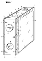
- the invention relates to a glass block with a dimensionally accurate frame made of plastic, which is provided on its circumferential surfaces with projections and depressions for fitting the glass blocks.
- Glass blocks of this type are known in which the dimensionally accurate frame is provided with tongue-and-groove recesses or projections which interlock when a wall part is constructed from such glass blocks and serve as a centering means (DE-AS 22 63 127).
- the frame can also be designed so that it is provided with lateral projections that extend to the glass edge of an adjacent glass block, while the frame of the adjacent glass block ends set back by the amount of these projections.
- the well-known framed glass blocks are glued together on their abutting surfaces with the interposition of an adhesive.
- the interlocking projections and recesses do not give each other the glass blocks with which they interact, but only prevent mutual displacement in one direction. Until the adhesive has set, there is a mutual displacement of the glass blocks in the other two directions possible, which can no longer be corrected after the adhesive has set.
- the invention has for its object to develop a glass block of the type mentioned in such a way that the construction of a wall part from such glass blocks is further simplified and facilitated.
- the frame should be designed so that the glass components can be connected to one another to form a firmly holding wall without the interposition of an adhesive layer.
- the butt joints of the abutting glass components should be sealed against the ingress of water, so that a wall constructed from such glass components is suitable for the creation of external walls both in terms of their mechanical strength and their tightness to moisture.
- this object is achieved in that the peripheral surfaces of the frame are provided on the one hand with three-dimensional projections and recesses which define the mutual position of the components in two spatial directions and enable a fixed plug connection, and on the other hand along the narrow sides with load-bearing frame-shaped projections, and that
- the frame consists of a plastic with a closed surface and a Shore D hardness of 7o to 85.
- the actual glass body 1 of the glass block consists of two half-stones 1a and 1b (FIG. 2) which are welded together to form a weld seam 2.
- glass blocks produced by other processes can of course also be provided with the frame 3 according to the invention. It may even be possible to use two half-stones not yet connected to one another instead of a complete glass block, and to provide them in the correct position with respect to one another with the frame, which in this case also has the task, in addition to the function according to the invention, for the fixed ones To ensure connection and sealing of the assembled glass block.
- the frame 3 is arranged as a closed, dimensionally accurate frame on the entire peripheral surface of the glass body 1.
- the outer dimensions of the frame 3 have narrow dimensional tolerances, so that the surfaces which interact with one another lie tightly against one another, and the connecting projections or recesses ensure a firm fit after being plugged together.
- the frame 3 is produced, for example, in a manner known per se according to the so-called “reaction foam casting process”, which is also known as the RIM process (reaction injection molding).
- reaction foam casting process which is also known as the RIM process (reaction injection molding).
- the plastic in liquid form is sprayed onto the peripheral surface of the glass body 1 within a correspondingly designed molding tool.
- the plastic hardens in the mold, so that the framed glass block is removed from the mold.
- adhesion promoters In order to increase the adhesion of the plastic to the glass surface, it is possible to use adhesion promoters or “primers” which are matched to the respective plastic and which are applied to the peripheral surface of the glass body before the glass body is inserted into the mold.
- adhesion promoters are commercially available and are selected in accordance with the plastic used for the framing.
- the peripheral surface 4 can be roughened or provided with a structure such that the surface in contact with the plastic of the frame is substantially larger than in the smooth state.
- This ge Desired enlargement of the glass surface is achieved by appropriate design of the mold walls of the molds with which the half stones 1-a, 1b are pressed.
- a sufficient enlargement of the glass surface can be achieved by corrugation, corrugation or other roughening of the wall of the mold.
- the outer circumferential surface of the framing 3 is assembled in which in example of FIG. 1 and 2 consists of a central plane surface 5, the excellent from this area 5 connecting projections 1 0, the protruding into the framing connecting recesses 12, the narrow sides 13 and along the the narrow sides 13 arranged, protruding from the surface 5 strip-like supporting projections 7. These projections 7 form the actual force-transmitting contact surfaces between the individual glass blocks.
- the projections 7 are separated from one another by a groove-shaped depression 8 .
- Each upper flat boundary surface of the projections 7 has a width B of approximately 2 to 4 mm
- the groove-shaped recess 8 has a width b of 1 to 3 mm, preferably of approximately 2 mm.
- This design of the projections 7 in connection with the elastic deformability of the plastic forming the frame creates a seal with favorable sealing properties.
- the groove-shaped recesses 8 of the glass blocks arranged next to one another in a wall part constructed from these glass blocks are connected to one another, and the perpendicular groove-shaped recesses 8 form, as it were, groove-like cavities through which water which has possibly penetrated through the first sealing surface can run off.
- connection projections 1o have the shape of circular cylinders. Their diameter d amounts to a total thickness D of the glass block of 80 mm-approximately 40 mm.
- the hollow cylindrical depressions 12 have corresponding dimensions.
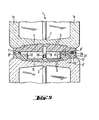
- the sealing projections 7 have a height H of, for example, 0.6 mm. When the glass blocks are joined together, this creates a cavity with a height of 1.2 mm between the flat boundary surfaces 5. This cavity serves for the insertion of reinforcing tapes 14.
- the reinforcing tapes 14 have holes 15 punched at the intervals specified by the projections 10 or depressions 12, and consist of a 1 mm thick metal tape.
- the reinforcement tapes 14 can be made of a suitable metal, such as Aluminum for low structural requirements, or stainless steel for very high structural requirements.
- the frame 3 consists of an integral foam, that is, a plastic with an unfoamed cover layer and a foamed core.
- a hard integral polyurethane foam with a molded foam density of 4oo to 7oo kg / m 3 , a flexural modulus according to DIN 53 423 from 95o to 11oo MPa is particularly suitable, a compressive strength according to DIN 53 421 with 1o% compression from 1o to 18 MPa, a Shore D hardness according to DIN 53 5 0 5 from 7o to 85, and a linear thermal expansion coefficient according to DIN 53 122 of ⁇ loo m / mK10 6 , each at a bulk density of 6 00 kg / m 3 .
- this cover layer plays a decisive role in these integral foams.
- this cover layer also has a significantly higher modulus of elasticity than the integral material.
- the modulus of elasticity of the cover layer can assume values up to 2ooo MPa.
- the conditions referred fulfilled in a satisfactory manner for example, the integral skin foam of the Fa. Bayer with the trade name BAYDUR 651o F.
- This material has kg at a density of 6 00 / m 3, a flexural E-modulus of 1o5o MPa, a compressive strength of 12 MPa, a Shore D hardness of 79, and a linear thermal expansion coefficient of 9o m / mK10 6 .
- a liquid blowing agent is added to the two polyol and isocyanate components which react to form the polyurethane, as a result of which the polyurethane formed during the reaction of the components foams.
- thermoplastic plastics are also suitable for the frame, insofar as their material properties, in particular their compressive strength and their elastic properties, are comparable with those of the integral foams mentioned.
- the protrusions 1 0 and the recesses can be mounted in principle 12 for the plug connectors in any arrangement.
- two opposite sides with projections lo, and the other two against each other overlying sides may be provided with depressions 12.
- two adjacent sides can also be provided with projections and depressions, or, as in the exemplary embodiments shown, alternately one projection 10 and one depression 12 can be provided on each side of the peripheral surface.
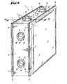
- recesses 16, 17, 18 are provided in the frame 3 at the points which are of no importance for the actual functions of the frame 3 with regard to the static properties and the tightness of a wall part composed of such glass blocks.
- the amount of plastic material of the frame 3 is significantly reduced, which brings with it a cost advantage, which is particularly significant when the plastic used is relatively expensive.
- the frame 3 of the glass block can also, as shown in the exemplary embodiment according to FIG. 4, be provided in the middle with longitudinal grooves 19, 19 'which extend to the bottom of the recesses 16, 17, 18. These longitudinal grooves 19, 19 'are used to insert a tension wire 2 0 , for example made of high-strength stainless steel.
- connection of the glass blocks with the aid of such tensioning wires is particularly suitable for those cases in which the glass blocks are not assembled to flat wall surfaces, but instead, for example, to cylindrical wall surfaces.
- only the peripheral surfaces of the frame need to be formed on one or more sides with the desired inclination, so that two adjoining stones form an angle different from 180 degrees.
- This method of mutual prestressing with the help of a tension wire also has the advantage that the required contact forces are generated exclusively in the wall part itself, without the adjacent structural parts being thereby put under tension.
- FIG. 5-sectional view of one recognizes the tension wire 2 0 within the longitudinal groove 19th
- this illustration shows a possibility of how there are particularly high demands on the watertightness of one of the glass blocks according to the invention an additional seal can be achieved on the wall.
- An injection-capable, permanently elastic sealing compound 27, for example based on silicone is injected under pressure through these bores 26 with the aid of a suitable spraying device provided with a cannula that can be inserted into the bore 26.
- the sealing compound 27 flows under the effect of the pressure through the longitudinal groove 8 'and thus ensures a reliable additional seal.
- these additional sealing measures are only carried out on the side of the wall part which is affected by the moisture or the water.
- the width b ' is advantageously approximately 3 mm and the height H' approximately 1.5 mm.
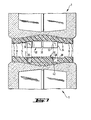
- the fastening projections arranged on the circumferential surfaces 5 have the shape of annular hollow cylinders 32.
- the inner wall surface 33 is slightly conical in that the diameter increases somewhat towards the outside.
- the outer wall surface 34 has a cylindrical shape.
- the hollow cylinders are in four Segments divided, which gives them the required elasticity.
- the fillet 36 at the foot of the hollow cylinder 32 also contributes to increasing the elasticity.
- the depression provided for receiving this hollow cylinder 32 in the frame of the adjacent glass block accordingly has the shape of an annular channel 38.
- the outer boundary surface 39 of the annular channel is cylindrical.
- the inner boundary surface 40 of the annular channel 38 has a slightly conical shape and forms the outer surface of a conical body 41. This cone 41 serves as an expanding cone for the segments of the hollow cylinder 32.
- the glass blocks are joined together using hammer blows.
- the segments of the hollow cylinder 32 are pressed apart by the expansion cone 41.
- the spreading reaches its greatest extent at the edge of the hollow cylinder 32.
- the hollow cylinder wall is anchored to a certain extent in the wall 39 of the ring channel near the base surface 42 of the ring channel 38, so that the force is introduced into the frame 3 at the most favorable point for reasons of strength becomes.
- the taper of the cone 41 and the hollow cone surface 33 of the sleeve 32 is relatively low. Good results are achieved if the angle of inclination of the surface lines of the cone 41 is four to eight degrees, and preferably about five degrees. Under these conditions, the connection is self-locking after assembly, so that unwanted loosening of the connection cannot occur.
- the cone 41 within the ring channel 38 can in turn also be designed as a hollow cone, in that it is merely designed as a ring. This saves material, on the one hand, and on the other hand, this cone can be given a certain elasticity, which can be advantageous with regard to possible manufacturing tolerances.
- FIG. 8 Another method for further increasing the cohesion or the strength of a wall part composed of glass blocks according to the invention is shown in FIG. 8.
- perforated strips 44 are clamped onto the narrow sides of the wall part.
- the perforated strips 44 can be made of metal or plastic and can be cut to the required length at the construction site.
- the perforated strips 44 are pushed onto the projections 10. Insofar as the glass blocks on this side do not have projections, but depressions 12, 12 connecting plugs 45 are inserted into these depressions, which take over the role of the projections at these points.
- a perforated strip 44 'of a length corresponding to the width of the wall part is first fastened to the concrete or masonry base 46, for example with the aid of dowels.
- cylindrical connecting plugs 45 are inserted into the recesses on the underside of the lowermost glass building blocks, and the bottom row of the glass building blocks are fastened to the perforated strip 44 'with the connecting projections 10 or the connecting plugs 45'.
- the wall part is put together in the desired size, will also be on the lateral and on the upper boundary surface of the wall part in the recesses of the frame connecting plug 45, and then pushed perforated strips 44 over the connecting projections 10 or connecting plug 45.
- the joints remaining up to the opening of the wall are then closed in the usual way, for example by mortar or by spraying with a plastic or plastic foam.
Landscapes
- Engineering & Computer Science (AREA)
- Architecture (AREA)
- Civil Engineering (AREA)
- Structural Engineering (AREA)
- Securing Of Glass Panes Or The Like (AREA)
- Building Environments (AREA)
Priority Applications (1)
| Application Number | Priority Date | Filing Date | Title |
|---|---|---|---|
| AT83108034T ATE20369T1 (de) | 1982-09-09 | 1983-08-13 | Glasbaustein, wandteil aus glasbauelementen, und verfahren zum verlegen und einbauen solcher glasbauelemente. |
Applications Claiming Priority (4)
| Application Number | Priority Date | Filing Date | Title |
|---|---|---|---|
| DE3233470 | 1982-09-09 | ||
| DE19823233470 DE3233470A1 (de) | 1982-09-09 | 1982-09-09 | Glasbauelement, insbesondere glasbaustein, wandteil aus glasbauelementen, und verfahren zum verlegen und einbauen solcher glasbauelemente |
| DE19833315942 DE3315942A1 (de) | 1983-05-02 | 1983-05-02 | Glasbauelement, insbesondere glasbaustein, mit einer massgenauen umrahmung aus kunststoff |
| DE3315942 | 1983-05-02 |
Publications (3)
| Publication Number | Publication Date |
|---|---|
| EP0103192A2 true EP0103192A2 (fr) | 1984-03-21 |
| EP0103192A3 EP0103192A3 (en) | 1985-01-30 |
| EP0103192B1 EP0103192B1 (fr) | 1986-06-11 |
Family
ID=25804349
Family Applications (1)
| Application Number | Title | Priority Date | Filing Date |
|---|---|---|---|
| EP83108034A Expired EP0103192B1 (fr) | 1982-09-09 | 1983-08-13 | Brique en verre, mur d'éléments en verre et procédé pour poser et monter de tels élément en verre |
Country Status (3)
| Country | Link |
|---|---|
| US (1) | US4628652A (fr) |
| EP (1) | EP0103192B1 (fr) |
| DE (1) | DE3364068D1 (fr) |
Cited By (11)
| Publication number | Priority date | Publication date | Assignee | Title |
|---|---|---|---|---|
| FR2687708A1 (fr) * | 1992-02-21 | 1993-08-27 | Ginailhac Frederic | Elements modulaires en bois servant aux montages de briques de verres. |
| EP0584659A1 (fr) * | 1992-08-13 | 1994-03-02 | Claus Dipl.-Ing. Permesang | Ensemble d'éléments pour la fabrication d'une paroi en briques de verre |
| WO1994016168A1 (fr) * | 1993-01-05 | 1994-07-21 | Patrick Vassal | Element de construction composite de parois pouvant etre transparentes et/ou isolantes et procede de fabrication de certains de ces elements |
| DE4412950C1 (de) * | 1994-04-14 | 1995-03-23 | Siemens Ag | Steckverbinder für Rückwandverdrahtungen |
| US5565654A (en) * | 1994-04-14 | 1996-10-15 | Siemens Aktiengesellschaft | Printed circuit board for plug-type connections |
| US5639263A (en) * | 1994-04-29 | 1997-06-17 | Siemens Aktiengesellschaft | Plug-type connector between wiring backplanes and assembly printed circuit boards |
| US5782656A (en) * | 1994-04-14 | 1998-07-21 | Siemens Aktiengesellschaft | Plug-type connector for backplate wirings |
| US5803768A (en) * | 1994-04-14 | 1998-09-08 | Siemens Aktiengesellschaft | Plug-type connector for backplane wirings |
| WO2008049952A1 (fr) * | 2006-10-23 | 2008-05-02 | Ancomap Dos, S.L. | Pièce préfabriquée pour la réalisation de parements |
| WO2017036593A1 (fr) * | 2015-08-31 | 2017-03-09 | Marco Semadeni | Élément de construction composé de briques creuses en verre |
| US20220136238A1 (en) * | 2019-02-26 | 2022-05-05 | Colin Christopher Felton | Interlocking Composite Construction Block |
Families Citing this family (27)
| Publication number | Priority date | Publication date | Assignee | Title |
|---|---|---|---|---|
| DK155170C (da) * | 1986-07-28 | 1989-07-03 | Sign D Sign A S | Plademonteringssystem, isaer til brug ved skiltning, og forbindelseselement dertil |
| US4984403A (en) * | 1989-10-25 | 1991-01-15 | Zarwell Daniel W | Modular building block |
| US5038542A (en) * | 1990-01-16 | 1991-08-13 | Glass Alternatives Corp. | Architectural building block herewith |
| US5033245A (en) * | 1990-01-16 | 1991-07-23 | Glass Alternatives Corp. | Architectural building block |
| US5675948A (en) * | 1995-04-13 | 1997-10-14 | Thermo-Vent Manufacturing, Inc. | Insulated ventilator for glass block window |
| US5904018A (en) * | 1996-06-20 | 1999-05-18 | Plamet Limited Liability Company | System of structural elements, particularly for building internal walls |
| US5836125A (en) * | 1996-07-29 | 1998-11-17 | Regina; Samuel R. | Interlocking translucent blocks |
| US6553733B1 (en) * | 1999-11-10 | 2003-04-29 | Pittsburgh Corning Corporation | Glass block with internal capsule |
| GB2376904B (en) * | 2001-06-30 | 2004-12-15 | Guy Bamford | Laminate concrete panel |
| US6964809B2 (en) | 2002-02-15 | 2005-11-15 | Pedro M. Buarque de Macedo | Large high density foam glass tile |
| US7150133B2 (en) * | 2002-05-08 | 2006-12-19 | Samuel R. Regina | Ventilated plastic blocks with film laminate |
| US7254924B2 (en) * | 2002-05-08 | 2007-08-14 | Regina Samuel R | solar reflective ventilated translucent blocks |
| US6988341B2 (en) * | 2002-05-08 | 2006-01-24 | Regina Samuel R | Ventilated interlocking translucent blocks |
| GB2398085B (en) | 2003-02-07 | 2006-08-23 | James Mcerlean | Glass block surround |
| GB2403228A (en) * | 2003-05-02 | 2004-12-29 | Philip Richardson | Blow moulded brick and method of production thereof |
| US7311965B2 (en) * | 2003-07-22 | 2007-12-25 | Pedro M. Buarque de Macedo | Strong, high density foam glass tile having a small pore size |
| US8453400B2 (en) | 2003-07-22 | 2013-06-04 | Pedro M. Buarque de Macedo | Prestressed, strong foam glass tiles |
| US20060156656A1 (en) * | 2005-01-19 | 2006-07-20 | Robinson Gerald M | Aggregate log and method of building construction |
| US7695560B1 (en) | 2005-12-01 | 2010-04-13 | Buarque De Macedo Pedro M | Strong, lower density composite concrete building material with foam glass aggregate |
| ES2267411B1 (es) * | 2006-03-27 | 2008-03-01 | Todo Paves, S.L. | "elemento modular de paves". |
| US8365683B2 (en) * | 2009-07-01 | 2013-02-05 | Mag-Life Llc | Aquarium structure |
| FR2958670A1 (fr) * | 2010-04-09 | 2011-10-14 | Sadika Keskes | Element de construction par soufflage ou soufflage-pressage. |
| CA2793668A1 (fr) | 2011-10-31 | 2013-04-30 | Bradley J. Crosby | Appareil et methode de construction de structures a l'aide de formes de beton isolees |
| CA2801735C (fr) | 2012-01-13 | 2019-08-06 | Bradley J. Crosby | Equipement et methode pour la construction de structures a partir de coffrages de beton isole |
| USD713975S1 (en) | 2012-07-30 | 2014-09-23 | Airlite Plastics Co. | Insulative insert for insulated concrete form |
| CA2985438A1 (fr) | 2016-11-14 | 2018-05-14 | Airlite Plastics Co. | Forme de beton a paroi amovible |
| US11155995B2 (en) | 2018-11-19 | 2021-10-26 | Airlite Plastics Co. | Concrete form with removable sidewall |
Family Cites Families (18)
| Publication number | Priority date | Publication date | Assignee | Title |
|---|---|---|---|---|
| US1028578A (en) * | 1908-02-10 | 1912-06-04 | Jens Gabriel Fredrick Lund | Straight vault. |
| GB175696A (en) * | 1920-10-21 | 1922-02-21 | Caroline Kelly | Improvements relating to concrete blocks for building purposes |
| US2176213A (en) * | 1936-08-22 | 1939-10-17 | Sealed Joint Products Co Inc | Building unit and structure formed therefrom |
| GB488640A (en) * | 1936-10-06 | 1938-07-06 | Latif Tewfik Makram | Improvements relating to bricks or blocks for general building and for furnaces |
| US2241169A (en) * | 1937-12-08 | 1941-05-06 | Yokes Otto | Building construction |
| US2877506A (en) * | 1953-08-10 | 1959-03-17 | Hans A Almoslino | Transformable rigid structural unit for a body or article supporting assemblage |
| US3374917A (en) * | 1964-01-09 | 1968-03-26 | Constantine T. Troy | Interlocking structural elements |
| FR1394241A (fr) * | 1964-02-20 | 1965-04-02 | Perfectionnement à la construction des murs en briques de verre | |
| US3534518A (en) * | 1968-09-27 | 1970-10-20 | Groutlock Corp | Interlocking building block construction |
| US3619370A (en) * | 1969-04-21 | 1971-11-09 | Frosst & Co Charles E | Microbial reduction of thiadiazoles |
| AT339015B (de) * | 1973-06-16 | 1977-09-26 | Jurgen Von Der Ley | Bauelement aus kunststoff |
| US4008931A (en) * | 1975-09-17 | 1977-02-22 | Lincoln Manufacturing Company, Inc. | End panel construction for modular units and modular unit embodying the end panel construction |
| US4031678A (en) * | 1975-11-20 | 1977-06-28 | Schuring James A | Interlocking building block construction |
| DE2613695A1 (de) * | 1976-03-31 | 1977-10-13 | Herwart Weber | Isolierprofil fuer glasbausteine |
| US4060952A (en) * | 1976-05-05 | 1977-12-06 | Gerardo Lopez Hernandez | Brick |
| US4058943A (en) * | 1976-06-03 | 1977-11-22 | Sturgill Lawrence W | Glass block panel |
| DK143510C (da) * | 1978-07-03 | 1982-01-18 | E Nielsen | Bygningselement,fortrinsvis murelement |
| US4428174A (en) * | 1979-04-04 | 1984-01-31 | Grady Ii Clyde C | Construction system |
-
1983
- 1983-08-13 EP EP83108034A patent/EP0103192B1/fr not_active Expired
- 1983-08-13 DE DE8383108034T patent/DE3364068D1/de not_active Expired
- 1983-08-26 US US06/527,176 patent/US4628652A/en not_active Expired - Fee Related
Cited By (14)
| Publication number | Priority date | Publication date | Assignee | Title |
|---|---|---|---|---|
| FR2687708A1 (fr) * | 1992-02-21 | 1993-08-27 | Ginailhac Frederic | Elements modulaires en bois servant aux montages de briques de verres. |
| EP0584659A1 (fr) * | 1992-08-13 | 1994-03-02 | Claus Dipl.-Ing. Permesang | Ensemble d'éléments pour la fabrication d'une paroi en briques de verre |
| WO1994016168A1 (fr) * | 1993-01-05 | 1994-07-21 | Patrick Vassal | Element de construction composite de parois pouvant etre transparentes et/ou isolantes et procede de fabrication de certains de ces elements |
| US5803768A (en) * | 1994-04-14 | 1998-09-08 | Siemens Aktiengesellschaft | Plug-type connector for backplane wirings |
| DE4412950C1 (de) * | 1994-04-14 | 1995-03-23 | Siemens Ag | Steckverbinder für Rückwandverdrahtungen |
| US5565654A (en) * | 1994-04-14 | 1996-10-15 | Siemens Aktiengesellschaft | Printed circuit board for plug-type connections |
| US5632652A (en) * | 1994-04-14 | 1997-05-27 | Siemens Aktiengesellschaft | Plug-type connector for backplane wirings |
| US5782656A (en) * | 1994-04-14 | 1998-07-21 | Siemens Aktiengesellschaft | Plug-type connector for backplate wirings |
| US5639263A (en) * | 1994-04-29 | 1997-06-17 | Siemens Aktiengesellschaft | Plug-type connector between wiring backplanes and assembly printed circuit boards |
| WO2008049952A1 (fr) * | 2006-10-23 | 2008-05-02 | Ancomap Dos, S.L. | Pièce préfabriquée pour la réalisation de parements |
| WO2017036593A1 (fr) * | 2015-08-31 | 2017-03-09 | Marco Semadeni | Élément de construction composé de briques creuses en verre |
| US10640976B2 (en) | 2015-08-31 | 2020-05-05 | Marco Semadeni | Component made of hollow glass blocks |
| US20220136238A1 (en) * | 2019-02-26 | 2022-05-05 | Colin Christopher Felton | Interlocking Composite Construction Block |
| US12577776B2 (en) * | 2019-02-26 | 2026-03-17 | Compositech Llc | Interlocking composite construction block |
Also Published As
| Publication number | Publication date |
|---|---|
| EP0103192A3 (en) | 1985-01-30 |
| DE3364068D1 (en) | 1986-07-17 |
| US4628652A (en) | 1986-12-16 |
| EP0103192B1 (fr) | 1986-06-11 |
Similar Documents
| Publication | Publication Date | Title |
|---|---|---|
| EP0103192B1 (fr) | Brique en verre, mur d'éléments en verre et procédé pour poser et monter de tels élément en verre | |
| EP0153660B1 (fr) | Elément de coffrage pour la construction à coffrage permanent | |
| DE69126601T2 (de) | Vorgefertigte Schalung | |
| DE69403902T2 (de) | Gussbetonwände | |
| EP1978179B1 (fr) | Système de raccordement et de verrouillage de deux panneaux de construction, en particulier des panneaux de plancher | |
| EP0194435A2 (fr) | Dispositif pour la réalisation de joints d'expansion dans des surfaces de plancher ou de béton | |
| EP0059171B1 (fr) | Boulon et canon pour la prise et la transmission d'une force transversale | |
| EP0751266B1 (fr) | Bloc à bancher | |
| DE10139261C2 (de) | Wandelement sowie Verfahren zu dessen Herstellung | |
| DE9308688U1 (de) | Schalungsstein | |
| DE3233470A1 (de) | Glasbauelement, insbesondere glasbaustein, wandteil aus glasbauelementen, und verfahren zum verlegen und einbauen solcher glasbauelemente | |
| EP0348870A1 (fr) | Construction constituée par l'assemblage d'éléments préfabriqués en béton armé utilisant la technique du béton précontraint | |
| EP4397820A1 (fr) | Unité de raccordement pour un drainage de toit comprenant un cadre de raccordement | |
| EP0335927A1 (fr) | Moule utile pour la fabrication d'elements de planchers similaires a des dalles pour former des doubles-fonds, elements de planchers similaires a des dalles ainsi produits | |
| DE2347007A1 (de) | Kraftschluessige verbindung von vorgefertigten betonbauteilen | |
| AT520407A1 (de) | Schalungselement | |
| EP0083438B1 (fr) | Elément de coffrage de matière synthétique dure en mousse pour le procédé de construction en béton, dit "à manteau" | |
| EP0239053A2 (fr) | Caisson de volet roulant préfabriqué, composé d'éléments en terre cuite assemblés et son procédé de fabrication | |
| EP1211035A2 (fr) | Elément de coffrage perdu et article fabriqué muni de cet élément | |
| EP0115279B1 (fr) | Système de pose et de raccordement à une paroi de blocs de verre pourvus d'un encadrement aux dimensions précises en matière synthétique | |
| WO2011144394A2 (fr) | Rail de montage | |
| DE102019003036B4 (de) | Wärmedämmbaugruppe | |
| DE9205533U1 (de) | Verbinder für Dehnfugen | |
| EP1918469A2 (fr) | Système de raccordement d'isolation thermique | |
| DE102004026429B3 (de) | Fugenbandhalterung sowie Herstellungsverfahren für Betonierungsabschnitte |
Legal Events
| Date | Code | Title | Description |
|---|---|---|---|
| PUAI | Public reference made under article 153(3) epc to a published international application that has entered the european phase |
Free format text: ORIGINAL CODE: 0009012 |
|
| AK | Designated contracting states |
Designated state(s): AT BE CH DE FR GB IT LI LU NL SE |
|
| PUAL | Search report despatched |
Free format text: ORIGINAL CODE: 0009013 |
|
| AK | Designated contracting states |
Designated state(s): AT BE CH DE FR GB IT LI LU NL SE |
|
| 17P | Request for examination filed |
Effective date: 19841213 |
|
| GRAA | (expected) grant |
Free format text: ORIGINAL CODE: 0009210 |
|
| AK | Designated contracting states |
Kind code of ref document: B1 Designated state(s): AT BE CH DE FR GB IT LI LU NL SE |
|
| PG25 | Lapsed in a contracting state [announced via postgrant information from national office to epo] |
Ref country code: NL Effective date: 19860611 Ref country code: IT Free format text: LAPSE BECAUSE OF FAILURE TO SUBMIT A TRANSLATION OF THE DESCRIPTION OR TO PAY THE FEE WITHIN THE PRESCRIBED TIME-LIMIT;WARNING: LAPSES OF ITALIAN PATENTS WITH EFFECTIVE DATE BEFORE 2007 MAY HAVE OCCURRED AT ANY TIME BEFORE 2007. THE CORRECT EFFECTIVE DATE MAY BE DIFFERENT FROM THE ONE RECORDED. Effective date: 19860611 Ref country code: BE Effective date: 19860611 |
|
| REF | Corresponds to: |
Ref document number: 20369 Country of ref document: AT Date of ref document: 19860615 Kind code of ref document: T |
|
| PG25 | Lapsed in a contracting state [announced via postgrant information from national office to epo] |
Ref country code: SE Effective date: 19860630 |
|
| REF | Corresponds to: |
Ref document number: 3364068 Country of ref document: DE Date of ref document: 19860717 |
|
| PG25 | Lapsed in a contracting state [announced via postgrant information from national office to epo] |
Ref country code: LU Free format text: LAPSE BECAUSE OF NON-PAYMENT OF DUE FEES Effective date: 19860831 |
|
| ET | Fr: translation filed | ||
| NLV1 | Nl: lapsed or annulled due to failure to fulfill the requirements of art. 29p and 29m of the patents act | ||
| PLBE | No opposition filed within time limit |
Free format text: ORIGINAL CODE: 0009261 |
|
| STAA | Information on the status of an ep patent application or granted ep patent |
Free format text: STATUS: NO OPPOSITION FILED WITHIN TIME LIMIT |
|
| 26N | No opposition filed | ||
| GBPC | Gb: european patent ceased through non-payment of renewal fee | ||
| PG25 | Lapsed in a contracting state [announced via postgrant information from national office to epo] |
Ref country code: GB Free format text: LAPSE BECAUSE OF NON-PAYMENT OF DUE FEES Effective date: 19881122 |
|
| PGFP | Annual fee paid to national office [announced via postgrant information from national office to epo] |
Ref country code: AT Payment date: 19890731 Year of fee payment: 7 |
|
| PGFP | Annual fee paid to national office [announced via postgrant information from national office to epo] |
Ref country code: CH Payment date: 19890817 Year of fee payment: 7 |
|
| PGFP | Annual fee paid to national office [announced via postgrant information from national office to epo] |
Ref country code: FR Payment date: 19900712 Year of fee payment: 8 |
|
| PG25 | Lapsed in a contracting state [announced via postgrant information from national office to epo] |
Ref country code: AT Effective date: 19900813 |
|
| PG25 | Lapsed in a contracting state [announced via postgrant information from national office to epo] |
Ref country code: LI Effective date: 19900831 Ref country code: CH Effective date: 19900831 |
|
| REG | Reference to a national code |
Ref country code: CH Ref legal event code: PL |
|
| PG25 | Lapsed in a contracting state [announced via postgrant information from national office to epo] |
Ref country code: FR Effective date: 19920430 |
|
| REG | Reference to a national code |
Ref country code: FR Ref legal event code: ST |
|
| PGFP | Annual fee paid to national office [announced via postgrant information from national office to epo] |
Ref country code: DE Payment date: 19931011 Year of fee payment: 11 |
|
| PG25 | Lapsed in a contracting state [announced via postgrant information from national office to epo] |
Ref country code: DE Effective date: 19950503 |